Tuya Sandwich Non-Rechargeable Battery Board
The Tuya Sandwich non-rechargeable battery power supply board is part of the Tuya Sandwich Evaluation Kit and is used to supply power to the master control board, Wi-Fi communication board, and function board.
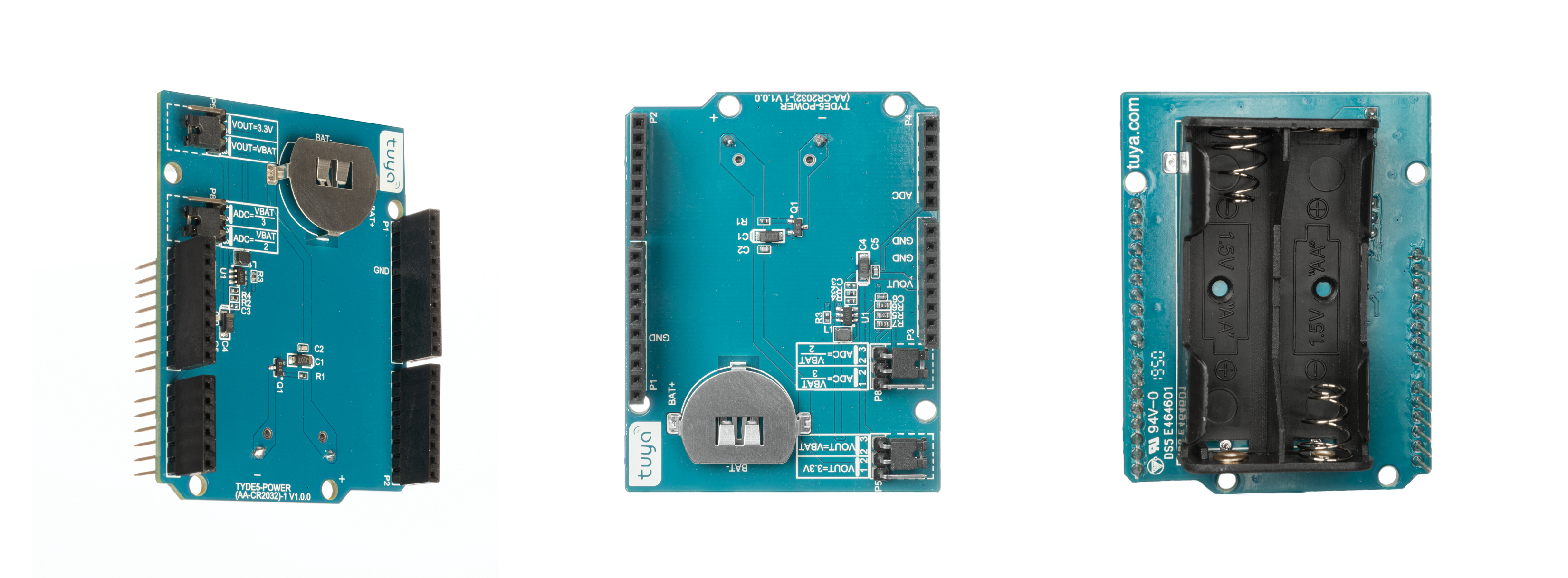
The power supply board supports one CR2032 battery or two AA batteries connected in series to supply power. You can select the primary voltage or 3.3V for the output voltage VOUT by adjusting the jump wire’s position of the P5 connector. And you can select VBAT/2 or VBAT/3 for ADC output by adjusting the jumper cap’s position of the P8 connector.
Introduction to key components
| Component | Description |
|---|---|
| U1(SY7072A) | High efficiency, 1 MHz switching frequency, 2A step-up chip, 5 uA quiescent current, and SOT23-6 package. |
Introduction to I/O ports
The definition of the pins on the power supply board is as follows:
| I/O | Description |
|---|---|
| VOUT | Power output. It outputs 3.3V or primary voltage. |
| GND | Power ground. |
| ADC | Battery level collection pin which outputs VBAT/2 or VBAT/3. |
Technical requirements
- Choose one CR2032 battery or two AA batteries as the power input.
- When you need to supply 3.3V power to other boards, choose AA batteries for boosting instead of a CR2032 battery.
Schematic diagram and PCB
-
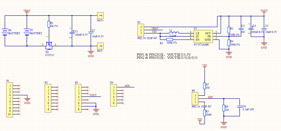
Schematic diagram of Tuya Sandwich non-rechargeable battery power supply board:
-
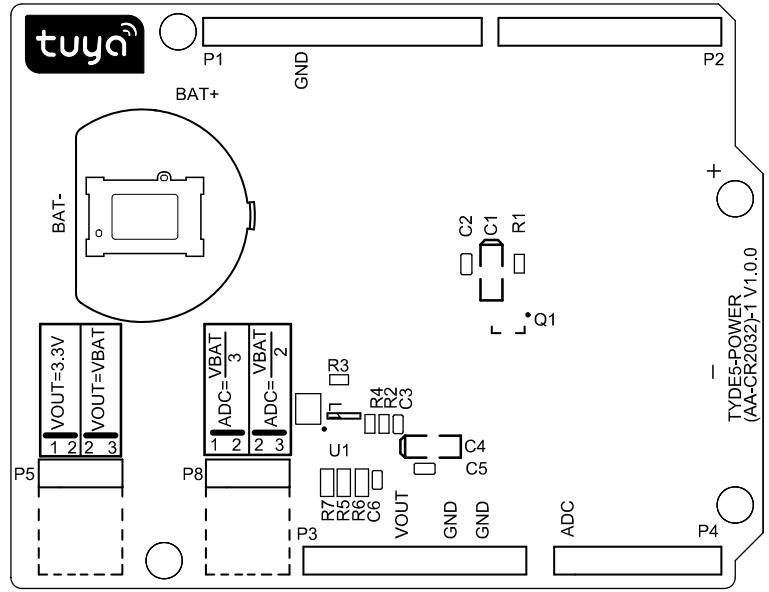
PCB of Tuya Sandwich non-rechargeable battery power supply board:
Things to note
- When all of the master control board, Wi-Fi communication board, and function board supports a wide voltage range, we recommend that you directly use the battery for power supply to improve battery utilization efficiency.
- When the operating current of the main control board, Wi-Fi communication board, and function board is big, use AA batteries instead of a CR2032 battery that can not provide sufficient current. When the module supports only 3.0V–3.6V voltage, choose 3.3V for VOUT to ensure the working reliability and full utilization of battery power.
- Pay attention to the voltage input range of the ADC port between the master control board and the Wi-Fi communication module. For example, because the ADC input voltage range of the E3S module is 0V–1.0V, you can only choose the VBAT/3 output for the power supply board. Otherwise, the ADC port might be damaged due to the high input voltage. You can also adjust the scale of R5, R6, and R7 according to your requirements.
Reference
Is this page helpful?
YesFeedbackIs this page helpful?
YesFeedback


