TYAUX-F Module Datasheet
TYAUX_F is a low power consumption module with a built-in Wi-Fi connectivity solution designed by Hangzhou Tuya Technology Corporation. The Wi-Fi Module consists of a highly integrated wireless radio chipRTL8710BN and some extra flash that has been programmed with Wi-Fi network protocol and plenty of software examples.
After a period of service, this module will become deprecated due to product upgrades and iterations, user requirements, production inventory, or other reasons. To improve the compatibility of your smart devices and minimize the impact on your use, Tuya continues to provide webpage documentation of deprecated modules, but no longer maintains or updates the documentation. The content herein is for reference only.
If you have any questions, submit a ticket to contact Tuya or consult Tuya’s account manager to request support.
Product overview
TYAUX_F includes ARM CM4F, WLAN MAC, 1T1R WLAN, maximum frequency reaches 125MHz, 256K SRAM, 2M byte flash, and various peripheral resources.
TYAUX_F is an RTOS platform, embedded with all the Wi-Fi MAC and TCP/IP protocol function examples, users can customize their Wi-Fi product by using these software examples.
Features
- Built-in low power-consuming 32-bit CPU functioning as an application processor
- Basic frequency: 125 MHz
- Working voltage: 3V-3.6V
- Peripherals: seven GPIOs, one UART
- Wi-Fi connectivity
- 802.11b/g/n20/n40
- Channels 1 to 14 at 2.4 GHz
- WPA/WPA2 security mode
- +18 dBm output power in 802.11b mode
- Smart network configuration function (for Android and iOS devices)
- PCB On board antenna
- Got the CE, FCC, and SRRC certification
- Working temperature: -20°C to +85°C
Applications
- Intelligent building
- Smart home and household appliances
- Healthcare
- Industrial wireless control
- Baby monitor
- Network camera
- Intelligent bus
Module interfaces
Dimensions and footprint
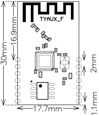
TYAUX_F has 2 columns of Pins (2*7). The distance between each Pin is 2 mm
TYAUX_F dimensions: 17.7mm±0.35mm(W)×30 ±0.35mm(L) ×3.6±0.15mm (H),PCB thickness is 1.0mm±0.1 mm,Figure as below :
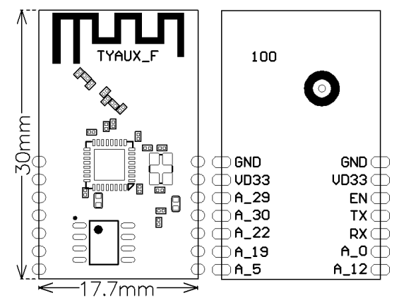
Interface pin definition
| Pin No. | Symbol | I/O Type | Function |
|---|---|---|---|
| 1 | GND | P | Power supply reference ground pin |
| 2 | VD33 | P | External power input (3.3 V) |
| 3 | GND | P | Power supply reference ground pin |
| 4 | EN | I/O | External reset signal (low-level effects) |
| 5 | TX | I/O | UART0_TXD (user serial port) |
| 4 | RX | I/O | UART0_RXD (user serial port) |
| 6 | A_0 | I/O | GPIOA_0, can not be pull-up while booting, can be used as GPIO while in normal working mode |
| 7 | A_12 | I/O | GPIOA_12, Hardware PWM(IC Pin17) |
| 8 | A_5 | I/O | GPIOA_5 Hardware PWM(IC Pin28) |
| 9 | A_19 | I/O | GPIOA_19, (IC Pin30) |
| 10 | A_22 | I/O | GPIOA_22, (IC Pin31) |
| 11 | A_30 | I/O | UART_Log_TXD (Used for printing the module internal information ), can be used as GPIO port |
| 12 | A_29 | I/O | UART_Log_RXD (Used for printing the module internal information ), can be used as GPIO port |
| 13 | VD33 | P | External power input (3.3 V) |
| 14 | GND | P | Power supply reference ground pin |
Note: P indicates power-supply pins, I/O indicates input/output pins
Electrical parameters
Absolute electrical parameters
| Parameter | Description | Minimum Value | Maximum Value | Unit |
|---|---|---|---|---|
| Ts | Storage temperature | -40 | 125 | °C |
| VCC | Power supply voltage | -0.3 | 3.6 | V |
| Static electricity voltage (human body model) | Tamb = 25°C | N/A | 2 | kV |
| Static electricity voltage (machine model) | Tamb = 25°C | N/A | 0.5 | kV |
Electrical conditions
| Parameter | Description | Minimum Value | Typical Value | Maximum Value | Unit |
|---|---|---|---|---|---|
| Ta | Working temperature | -20 | N/A | 85 | °C |
| VCC | Power supply voltage | 3.0 | 3.3 | 3.6 | V |
| VIL | I/O low-level input | -0.3 | - | VDD*0.25 V | |
| VIH | I/Ohigh-level input | VDD*0.75 | N/A | 3.6 | V |
| VOL | I/O low-level output | N/A | N/A | VDD*0.1 | V |
| VoH | I/O high-level output | VDD*0.8 | N/A | VDD | V |
| Imax | I/O drive current | N/A | 6 | 16 | mA |
| Cpad | Input pin capacitance | - | 2 | - | pF |
Continuous TX power dissipation
| Working Status | Mode | Rate | TX Power | Typical Value | Unit |
|---|---|---|---|---|---|
| TX | 11b | 11Mbps | +17dBm | 287 | - |
| TX | 11b | 11Mbps | +18dBm | 295 | - |
| TX | 11g | 54Mbps | +15dBm | 255 | - |
| TX | 11g | 54Mbps | +17.5dBm | 267 | - |
| TX | 11n BW20 | MCS7 | +13dBm | 244 | - |
| TX | 11n BW20 | MCS7 | +16.5dBm | 257 | - |
| TX | 11n BW40 | MCS7 | +13dBm | 220 | - |
| TX | 11n BW40 | MCS7 | +16.5dBm | 230 | - |
Continuous RX power dissipation
| Working Status | Mode | Rate | Receiving | Typical Value | Unit |
|---|---|---|---|---|---|
| RX | CPU Sleep | 11Mbps | Continuous RX 90 | - | mA |
| RX | CPU Active | MCS7 BW20 | Continuous RX | 120 | - |
Working current
| Working Mode | Working Status (Ta = 25°C) | Average Value | Peak Value*(Typical Value) | Unit |
|---|---|---|---|---|
| Quick configuration | Module in the quick net-pairing state, Wi-Fi indicator blinking | 115 | 125 | mA |
| Network connection idle | Module connected to the network, Wi-Fi indicator constantly on | 60 | 209 | mA |
| Network connection active | Module connected to the network, Wi-Fi indicator constantly on | 118 | 198 | mA |
| Disconnected | Module not connected to the network, Wi-Fi indicator always off | 34 | 192 | mA |
Note: The preceding parameter values vary depending on the firmware functions.
RF features
Basic RF features
| Parameter | Description |
|---|---|
| Frequency band | 2.412 GHz to 2.4835 GHz |
| Wi-Fi standard | IEEE 802.11b/g/n (channels 1 to 14) |
| Data transmission rate | 11b:1,2,5.5, 11 (Mbps); 11g:6,9,12,18,24,36,48,54(Mbps); 11n: HT20 MCS0~7; 11n: HT40 MCS0~7 |
| Antenna type | PCB onboard antenna |
TX performance
| Parameter | Minimum Value | Typical Value | Maximum Value | Unit |
|---|---|---|---|---|
| Average RF output power, 802.11b CCK mode 11 Mbit/s | N/A | 17.5 | N/A | dBm |
| Average RF output power, 802.11g OFDM mode 54 Mbit/s | N/A | 14.5 | N/A | dBm |
| Average RF output power, 802.11n OFDM mode MCS7 | N/A | 13.5 | N/A | dBm |
| Frequency error | -20 | N/A | +20 | ppm |
RX performance
| Parameter | Minimum Value | Typical Value | Maximum Value | Unit |
|---|---|---|---|---|
| PER < 8%, 802.11b CCK mode 1 Mbit/s | N/A | -91 | N/A | dBm |
| PER < 10%, 802.11g OFDM mode 54 Mbit/s | N/A | -75 | N/A | dBm |
| PER < 10%, 802.11n OFDM mode MCS7 | N/A | -72 | N/A | dBm |
Antenna
Antenna type
TYAUX-F supports onboard PCB antenna and external antenna. By default, the module uses an onboard PCB antenna.
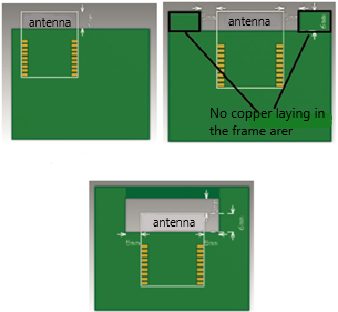
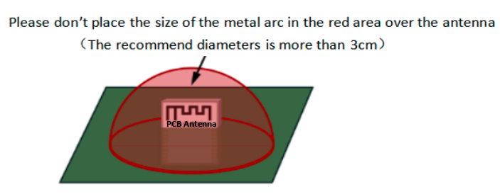
Antenna interference reduction
To ensure optimal Wi-Fi performance when the Wi-Fi module uses an onboard PCB antenna, it is recommended that the antenna be at least 15 mm away from other metal parts. To prevent an adverse impact on the antenna radiation performance, avoid copper or traces along the antenna area on the PCB.
U.FL RF connector
There is no antenna connector in this module.
Packaging information and production instructions
Mechanical dimensions
Production instructions
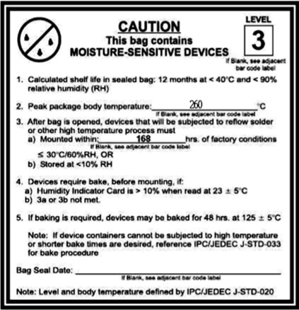
The storage for the delivered module should meet the following condition:
- The anti-moisture bag should be kept in an environment with temperature< 30℃ and humidity< 85%.
- The expiration date is 6 months since the dry packaging products were sealed.
Cautions :
- All the operators should wear an electrostatic ring throughout the whole process of production.
- While operating, water and dirt should not have any contact with the modules.
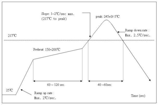
Recommended oven temperature curve
Perform SMT placement based on the following reflow oven temperature curve. The highest temperature is 245°C.
Storage conditions
MOQ and packaging information
| Product number | MOQ(pcs) | Shipping packaging method | Modules per reel | Packaging reels per box |
|---|---|---|---|---|
| TYAUX-F | 3600 | Tape reel | 900 | 4 |
Appendix: Statement
FCC Caution: Any changes or modifications not expressly approved by the party responsible for compliance could void the user’s authority to operate this device.
This device complies with Part 15 of the FCC Rules. Operation is subject to the following two conditions: (1) This device may not cause harmful interference, and (2) this device must accept any interference received, including interference that may cause undesired operation.
Note: This device has been tested and found to comply with the limits for a Class B digital device, according to part 15 of the FCC Rules. These limits are designed to provide reasonable protection against harmful interference in a residential installation. This device generates, uses, and can radiate radio frequency energy and, if not installed and used following the instructions, may cause harmful interference to radio communications. However, there is no guarantee that interference will not occur in a particular installation.
If this device does cause harmful interference to radio or television reception, which can be determined by turning the device off and on, the user is encouraged to try to correct the interference by one or more of the following measures:
- Reorient or relocate the receiving antenna.
- Increase the separation between the device and receiver.
- Connect the device to an outlet on a circuit different from that to which the receiver is connected.
- Consult the dealer or an experienced radio/TV technician for help.
Radiation Exposure Statement
This device complies with FCC radiation exposure limits set forth for an uncontrolled rolled environment. This device should be installed and operated with a minimum distance of 20cm between the radiator and your body.
Important Note
This radio module must not be installed to co-locate and operate simultaneously with other radios in the host system except by following FCC multi-transmitter product procedures. Additional testing and device authorization may be required to operate simultaneously with other radios.
The availability of some specific channels and/or operational frequency bands are country dependent and are firmware programmed at the factory to match the intended destination. The firmware setting is not accessible to the end-user.
The host product manufacturer is responsible for compliance with any other FCC rules that apply to the host not covered by the modular transmitter grant of certification. The final host product still requires Part 15 Subpart B compliance testing with the modular transmitter installed.
The end-user manual shall include all required regulatory information/warnings as shown in this manual, including "This product must be installed and operated with a minimum distance of 20 cm between the radiator and user body".
This device has got an FCC ID: 2ANDL-TYAUX-F. The end product must be labeled in a visible area with the following: "Contains Transmitter Module FCC ID: 2ANDL-TYAUX-F".
This device is intended only for OEM integrators under the following conditions:
The antenna must be installed such that 20cm is maintained between the antenna and users, and the transmitter module may not be co-located with any other transmitter or antenna.
As long as the 2 conditions above are met, further transmitter tests will not be required. However, the OEM integrator is still responsible for testing their end-product for any additional compliance requirements required with this module installed.
Declaration of Conformity European Notice

Hereby, Hangzhou Tuya Information Technology Co., Ltd declares that this module product is in compliance with essential requirements and other relevant provisions of Directive 2014/53/EU,2011/65/EU. A copy of the Declaration of Conformity can be found at https://www.tuya.com.

This product must not be disposed of as normal household waste, in accordance with the EU directive for waste electrical and electronic equipment (WEEE-2012/19/EU). Instead, it should be disposed of by returning it to the point of sale, or to a municipal recycling collection point.
The device could be used with a separation distance of 20cm from the human body.
Is this page helpful?
YesFeedbackIs this page helpful?
YesFeedback


