Production Test on Wi-Fi Socket without Energy Monitoring Function
This topic describes how to use a finished product of a Wi-Fi no-code non-energy monitoring socket to test the Wi-Fi function and the capability of communication between modules and control boards in the solutions of single-indicator multiplexing, dual-indicator mixed-color, and dual-indicator separated-color.
Background information
- Single-indicator multiplexing solution: the same indicator for both the Wi-Fi and power supply.
- Dual-indicator mixed-color solution: separate indicators for the Wi-Fi and power supply respectively that can illumine simultaneously to form a mixed lighting color.
- Dual-indicator separated-color solution: separate indicators for the Wi-Fi and power supply respectively that cannot illumine simultaneously.
Application scope
It applies to no-code solutions for Wi-Fi non-energy monitoring sockets whose firmware supports the new production test process (the production test can be repeated).
Indicator of a successful production test
- Single-indicator multiplexing solution:
- Single socket: When the socket switch is pressed once, the relay flips three times. The Wi-Fi indicator exits the on-off cycle and turns on and off synchronously with the relay flips.
- Power strip: When the master switch of the power strip is pressed once, each relay flips three times, and the Wi-Fi indicator exits the on-off cycle and stays on.
- Dual-indicator mixed-color solution:
- Single socket: When the socket switch is pressed once, the relay flips three times. The Wi-Fi indicator keeps flickering quickly, and the power indicator turns on and off synchronously with the relay flips.
- Power strip: When the master switch of the power strip is pressed once, each relay flips three times. The Wi-Fi indicator keeps flickering quickly, and the power indicator turns on and off synchronously with the relay flips.
- Dual-indicator separated-color solution:
- Single socket: When the socket switch is pressed once, the relay flips three times. The Wi-Fi indicator exits the on-off cycle and stays off.
- Power strip: When the master switch of the power strip is pressed once, each relay flips three times. The Wi-Fi indicator exits the on-off cycle and stays off.
Things to note
- Place the device under test three to five meters away from the router without any obstacles.
Note: When using the surrounding aging rack for production testing, make sure that the device under test will not be blocked by metal or surrounded by other products.
- Within the Wi-Fi coverage area of the same router, make sure no more than 200 products are tested at the same time. If you have more than 200 products to test, you need to have one more router for every 200 more products.
- In the production test environment, use as few non-test routers as possible to reduce interference thus speeding up the production test.
- Remove paired devices from the app with the network and wait 10 seconds to power them off before starting the production test.
Preparation
Device preparation
| Device | Quantity | Note |
|---|---|---|
| Device under test | 1 | / |
| Production test backplane (PCBA) | 1 | / |
| 2.4 GHz signal router for production test | At least one | Internet connection is not required. |
| Stable isolated power supply | 1 | The adjustable voltage includes 220V and 120V, and the output power can be viewed. |
Deployment preparation
- Place a powered-on 2.4 GHz router three to five meters away from the device, and set the SSID of the router to
tuya_mdev_test1. - Connect the AC stable isolated power supply to the input live wire LIN and the input neutral wire N of the control board.
Production test process
- Single-indicator multiplexing solution
- Dual-indicator mixed-color solution
- Dual-indicator separated-color solution
Procedure
Single-indicator multiplexing solution
-
Power on the router with the SSID of
tuya_mdev_test1. -
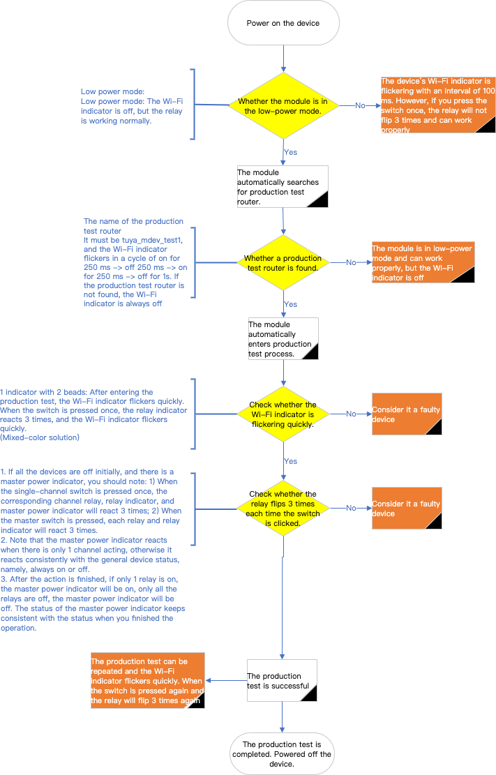
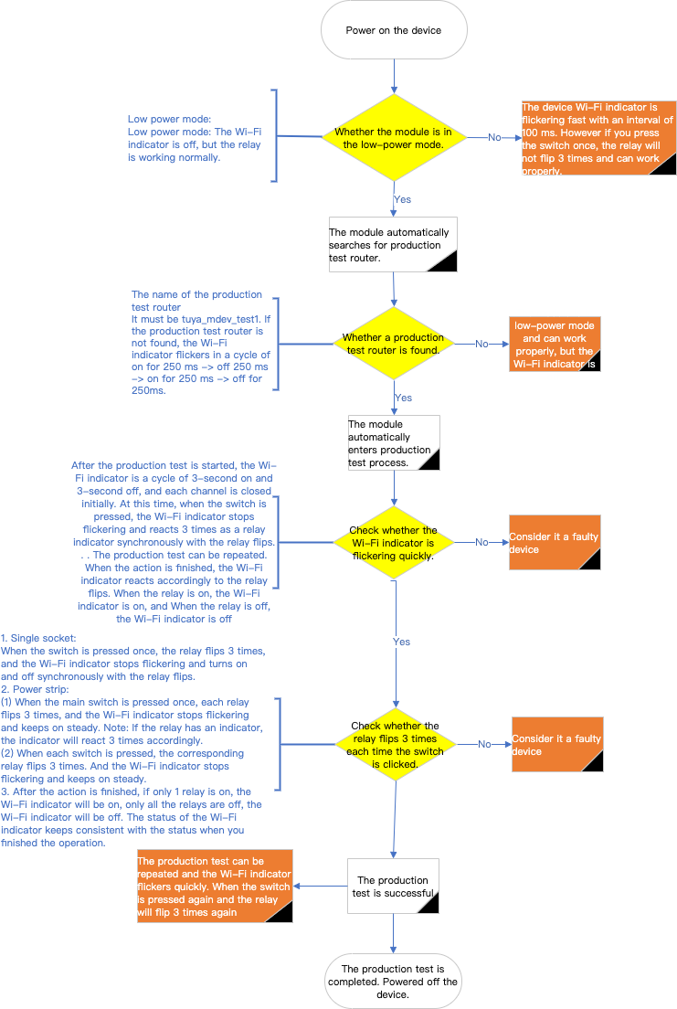
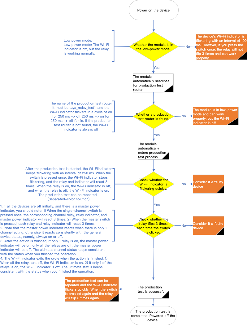
Power on the socket under test and check whether the module is in low power mode.
- Low power mode: The Wi-Fi indicator is off, but the relay is working normally.
- Non-low-power mode: The Wi-Fi indicator will turn on and off at an interval of 100 milliseconds, but the relay will not flip three times after the switch is pressed, and it can still work normally. At this time, you need to power off the router, use the app to pair the socket under test, and then remove the device and wait 10 seconds before powering off. After power-on again, the device will enter low power mode by default.
-
Make sure the module is in low power mode and check whether the module is connected to the router and under production test automatically.
- Success: The Wi-Fi indicator is a cycle of three-second on and three-second off.
- Failure: The Wi-Fi indicator is a cycle of 250-millisecond on and 250-millisecond off, and the socket can be considered a faulty device.
-
Make sure the module is under production test and check whether the production test is successful.
- Success (single socket): When the socket switch is pressed once, the relay flips three times. The Wi-Fi indicator exits the on-off cycle and turns on and off synchronously with the relay flips.
- Success (power strip): When the master switch of the power strip is pressed once, each relay flips three times, and the Wi-Fi indicator exits the on-off cycle and stays on.
Note:
- If the relay has an indicator, the indicator will turn on and off synchronously with the relay flips.
- If the relay only flips once, it indicates that the device is not in low-power mode. Refer to the processing method in step 2 to make the device enter the low-power mode, and restart the production test.
- Failure: The relay and Wi-Fi indicator will not enter the above-mentioned status, and the socket can be considered a faulty device.
-
Power off the socket under test.
Dual-indicator mixed-color solution
- Refer to step 1 and step 2 of the single-indicator multiplexing solution.
- Make sure the module is in low power mode and check whether the module is connected to the router and under production test automatically.
- Success: The Wi-Fi indicator is on for 250 milliseconds, off for 250 milliseconds, on for 250 milliseconds, and off for one second.
- Failure: The Wi-Fi indicator is always off, and the socket can be considered a faulty device.
- Make sure the module is under production test and check whether the production test is successful.
- Success (single socket): When the socket switch is pressed once, the relay flips three times. The Wi-Fi indicator keeps flickering quickly, and the power indicator turns on and off synchronously with the relay flips.
- Success (power strip): When the master switch of the power strip is pressed once, each relay flips three times. The Wi-Fi indicator keeps flickering quickly, and the power indicator turns on and off synchronously with the relay flips.
Note:
- If the relay has an indicator, the indicator will turn on and off synchronously with the relay flips.
- If the relay only flips once, it indicates that the device is not in low-power mode. Refer to the processing method in step 2 of the single-indicator multiplexing solution to make the device enter the low-power mode, and restart the production test.
- Failure: The relay and Wi-Fi indicator will not enter the above-mentioned status, and the socket can be considered a faulty device.
- Power off the socket under test.
Dual-indicator separated-color solution
- Refer to step 1 and step 2 of the single-indicator multiplexing solution.
- Make sure the module is in low power mode and check whether the module is connected to the router and under production test automatically.
- Success: The Wi-Fi indicator is on for 250 milliseconds, off for 250 milliseconds, on for 250 milliseconds, and off for one second.
- Failure: The Wi-Fi indicator is always off, and the socket can be considered a faulty device.
- Make sure the module is under production test and check whether the production test is successful.
- Success (single socket): When the socket switch is pressed once, the relay flips three times. The Wi-Fi indicator exits the on-off cycle and stays off.
- Success (power strip): When the master switch of the power strip is pressed once, each relay flips three times. The Wi-Fi indicator exits the on-off cycle and stays off.
Note:
- If the relay has an indicator, the indicator will turn on and off synchronously with the relay flips.
- If the relay only flips once, it indicates that the device is not in low-power mode. Refer to the processing method in step 2 of the single-indicator multiplexing solution to make the device enter the low-power mode, and restart the production test.
- Failure: The relay and Wi-Fi indicator will not enter the above-mentioned status, and the socket can be considered a faulty device.
- Power off the socket under test.
Is this page helpful?
YesFeedbackIs this page helpful?
YesFeedback


