Application Development
A smart device has basic features including network connection, device control, status reporting, and OTA updates as well as firmware flashing and authorization, and production testing. This topic describes how the Zigbee SDK works and how to use it to implement the required features.
How it works
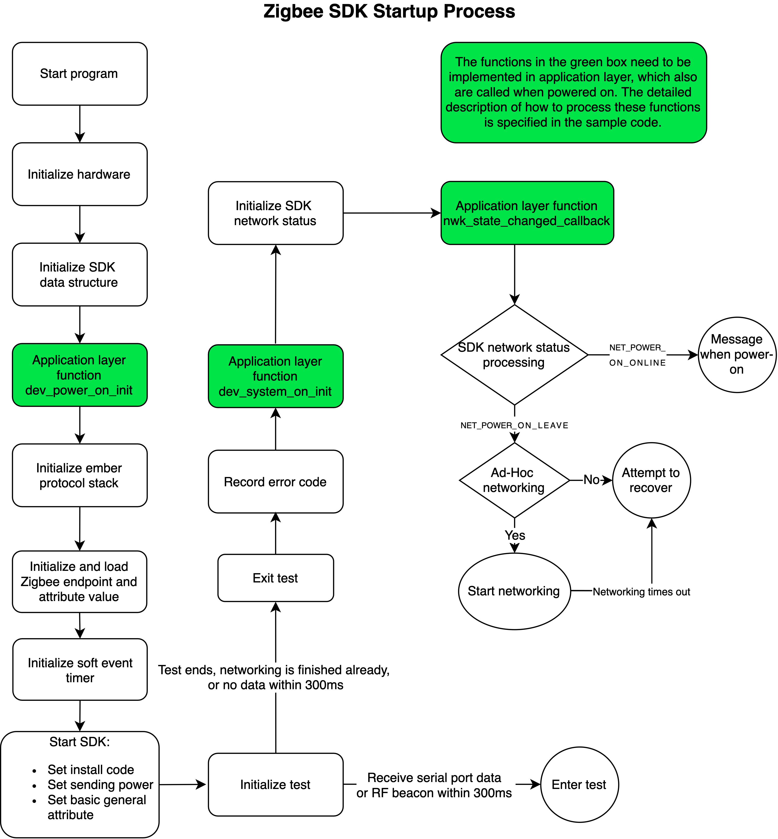
The following block diagram shows how the SDK is run and the functions used in this process.
Function description
| Function name | Description |
|---|---|
dev_power_on_init |
It is the first function that is run after device startup. In this function, you must implement Zigbee device creation and network forming configuration. |
dev_system_on_init |
It is the first feature function that is run after device startup. In this function, you can set Zigbee attributes and initialize the hardware and the software timer. |
nwk_state_changed_callback |
It is called to handle the Zigbee network status changes. |
Quick initialization
In the function dev_power_on_init, you need to implement Zigbee device creation and parameter configuration, such as device type (router or end device), and joining and rejoining Zigbee network.
The CPU and clock should be initialized before this function is called.
/**
 * @note (MUST) This is the first function after the hardware starts.
 * The CPU and the base clock are initialized before calling this function.
 * You need to implement the creation of Zigbee devices and
 * determine the parameters of Zigbee device behavior.
 * Include device roles(router, end device), device networking(join),
 * rejoin parameters and more. Refer to the Tuya Zigbee SDK demo for details.
 * @param none
 * @return none
 */
void dev_power_on_init(void);
Sample code snippet
void dev_power_on_init(void)
{
    join_config_t cfg;
    zg_dev_config_t zg_dev_config;

        /**
   Create Zigbee devices based on Zigbee specifications.
    Register a complete Zigbee device with the necessary components included such as endpoint, cluster, and attribute.
        */
    dev_register_zg_ep_infor((dev_description_t *)g_dev_des, EP_SUMS); // This function must be called in `power_on_init`.

        memset(&zg_dev_config, 0, sizeof(zg_dev_config_t));
    zg_dev_config.dev_type = ZG_ROUTER;
    dev_register_zg_dev_config(&zg_dev_config); // Configure the type of Zigbee devices (router or end device) as well as joining and rejoining the network.

        memset(&cfg, 0, sizeof(cfg));
    cfg.auto_join_power_on_flag = TRUE;
    cfg.auto_join_remote_leave_flag = TRUE;
    cfg.join_timeout = ZIGBEE_JOIN_MAX_TIMEOUT; // Configure the network forming policy after power on and remote deletion.
    dev_zg_join_config(&cfg);

        //TODO: others task
    return;
}
Zigbee device creation and basic configuration
| APIs | Description | Limit |
|---|---|---|
dev_register_zg_ep_infor |
Register a complete Zigbee device with the necessary components included such as endpoint, cluster, and attribute. | It can only be called in dev_power_on_init. |
dev_register_zg_dev_config |
Configure the type of Zigbee devices (router or end device) as well as joining and rejoining the network. | It can only be called in dev_power_on_init. |
dev_zg_join_config |
Configure the network forming policy after power on and remote deletion. | It can only be called in dev_power_on_init. |
Stack and component initialization
dev_system_on_init is the first feature function that is run after device startup. Before this function is called, Zigbee stack and some basic components have been started. In this function, you can set Zigbee attributes and initialize the hardware and the software timer.
/**
 * @note (MUST) This is the first function after the hardware starts.
 * The CPU and the base clock are initialized before calling this function.
 * You need to implement the creation of Zigbee devices and
 * determine the parameters of Zigbee device behavior.
 * Include device roles(router, end device), device networking(join),
 * rejoin parameters and more. Refer to the Tuya Zigbee SDK demo for details.
 * @param none
 * @return none
 */
void dev_power_on_init(void);
Sample code snippet
static void __uart_rx_callback(uint8_t *data, uint16_t len)
{
    //TODO: The serial receive handler.
}

static void __dev_evt_callback(uint8_t evt)
{
    switch(evt) {
        case EVT_LOCK_CANCEL: {
            //TODO: The custom event handler.
            break;
        }

                default: {
            break;
        }
    }
}

void dev_system_on_init(void)
{
    user_uart_config_t *p_default_cfg = mf_test_uart_config();
    user_uart_config_t uart_cfg;
    memcpy(&uart_cfg, p_default_cfg, sizeof(user_uart_config_t));
    uart_cfg.func = __uart_rx_callback;
    user_uart_init(&uart_cfg); // Configure the UART, including the UART hardware parameter and the UART receive and transmit callback.
    dev_timer_start_with_callback(EVT_LOCK_CANCEL, 1000, __dev_evt_callback);// Start a delay event and set the event handler.
    dev_change_power(11, 19);// Configure the transmission power.
    return;
}
Network forming
This function is used to discover Zigbee networks. If a device has joined a network, it will leave the current network and then start Zigbee network discovery.
/**
 * @description: join start delay timer hander, join now
 * @param {none}
 * @return: none
 */
void network_join_start_delay_timer_callback(void)
{
    dev_zigbee_join_start(ZIGBEE_JOIN_MAX_TIMEOUT); //
}
This function is called after the Zigbee network status changes are detected. It is recommended to handle network status in this function.
/**
 * @note (MUST) This function is invoked when the network state changes.
 * Handling network-related matters at this function is recommended.
 * @param[in] {state} Refer to NET_EVT_T for more detail.
 * @return none
 */
void nwk_state_changed_callback(NET_EVT_T state);
Sample code snippet
void nwk_state_changed_callback(NET_EVT_T state)
{
    switch(state) {
        case NET_POWER_ON_LEAVE: {
            //TODO: Network not connected after power on.
            break;
        }
        case NET_JOIN_START: {
            //TODO: Initiate network forming.
            break;
        }
        case NET_JOIN_TIMEOUT: {
            //TODO: Network forming failed.
            break;
        }
        case NET_POWER_ON_ONLINE: {
            //TODO: Network connected after power on.
            break;
        }
        case NET_JOIN_OK: {
            //TODO: Network forming succeeded.
            break;
        }
        case NET_REJOIN_OK: {
            //TODO: Connection retry succeeded.
            break;
        }
        case NET_LOST: {
            //TODO: Lost connection to parent.
            break;
        }
        case NET_REMOTE_LEAVE: {
            //TODO: Notify of leaving network initiated by remote control.
            break;
        }
        case NET_LOCAL_LEAVE: {
            //TODO: Notify of leaving network initiated by local control.
            break;
        }
        case NET_MF_TEST_LEAVE: {
            //TODO: Notify of leaving network initiated by production testing.
            break;
        }
        default: {
            break;
        }
    }
}
Data reception handler
After receiving data from the gateway or mobile app, the SDK will retrieve and run the data reception callback. You need to implement the data parsing and command execution in this callback.
dev_msg_recv_callback is used to receive data from the Zigbee gateway. The following code snippet uses the switch as an example to show you the data reception handler.
/**
 * @description: device receive message callback
 * @param {*dev_msg} received message information
 * @return: ZCL_CMD_RET_T
 */
ZCL_CMD_RET_T dev_msg_recv_callback(dev_msg_t *dev_msg)
{
    ZCL_CMD_RET_T result = ZCL_CMD_RET_SUCCESS;
    switch (dev_msg->cluster)
    {
        case CLUSTER_PRIVATE_TUYA_CLUSTER_ID: //private data processing
        {
            break;
        }
        case CLUSTER_ON_OFF_CLUSTER_ID: //0x0006 Zigbee ON OFF Cluster //standard data processin
        {
            attr_value_t *attr_list = dev_msg->data.attr_data.attr_value;
            uint8_t attr_sums = dev_msg->data.attr_data.attr_value_sums;
            uint8_t i;
            for(i = 0; i < attr_sums; i++)
            {
                switch(attr_list[i].cmd)
                {
                    case CMD_OFF_COMMAND_ID: // Turn off the switch.
                    {
                        __dev_switch_op(dev_msg->endpoint, DEV_IO_OFF); // Execute the command.
                        __dev_report_onoff_msg(dev_msg->endpoint, QOS_0);// Report the current status of the switch.
                        break;
                    }
                    case CMD_ON_COMMAND_ID: // Turn on the switch.
                    {
                        __dev_switch_op(dev_msg->endpoint, DEV_IO_ON);
                        __dev_report_onoff_msg(dev_msg->endpoint, QOS_0);
                        break;
                    }
                    case CMD_TOGGLE_COMMAND_ID: // Negation command
                    {
                        __dev_switch_op(dev_msg->endpoint, (DEV_IO_ST_T)! g_relay_onoff_status[dev_msg->endpoint - 1]);
                        __dev_report_onoff_msg(dev_msg->endpoint,QOS_0);
                        break;
                    }
                    default:
                    {
                        break;
                    }
                }
                break;
            }
        }
        default:
            // Unrecognized cluster ID, error status will apply.
            break;
    }
    return result
dev_msg_write_attr_callback_ext or dev_msg_write_attr_callback is used to notify the application layer of the write commands of Zigbee global classes.
void dev_msg_write_attr_callback(uint8_t endpoint, CLUSTER_ID_T cluster, uint16_t attr_id)
{
    //TODO: Call this function after writing to property is successfully run.
    return;
}

void dev_msg_write_attr_callback_ext(
    uint8_t endpoint,
    CLUSTER_ID_T cluster,
    uint16_t attr_id,
    uint8_t mask,
    uint16_t manufacturer_code,
    uint8_t type,
    uint8_t size,
    uint8_t* value)
{
    //TODO: Call this function after writing to property is successfully run, with the raw data carried.
    return;
}
Report data to the cloud
When the device status changes, the SDK calls the data reporting function based on the DPs to synchronize the current DP status with the cloud and the mobile app.
static void __send_result_cb(SEND_ST_T st, dev_send_data_t *msg)
{
    switch(st) {
        case SEND_ST_OK: {
            //TODO: Data is sent successfully.
            break;
        }
        default: {
            //TODO: Failed to send the data.
            break;
        }
    }
}

static void send_data_demo(void)
{
    dev_send_data_t send_data;

        memset(&send_data, 0, sizeof(dev_send_data_t));

    send_data.zcl_id = 0;  /// The user-defined ID, which is returned in the sending callback.
    send_data.qos = QOS_1; /// Data packet will be sent again if no acknowledgement is received.
    send_data.direction = ZCL_DATA_DIRECTION_SERVER_TO_CLIENT;
    send_data.command_id = CMD_REPORT_ATTRIBUTES_COMMAND_ID;       /// The command used to report property values.
    send_data.addr.mode = SEND_MODE_GW;                            /// Send data to the gateway.
    send_data.addr.type.gw.cluster_id = CLUSTER_ON_OFF_CLUSTER_ID; /// The on/off property.
    send_data.addr.type.gw.src_ep = 1; /// The endpoint.
    send_data.delay_time = 0;   /// The timer for delaying packet sending.
    send_data.random_time = 0;  /// The time range for random sending.
    send_data.data.zg.attr_sum = 1;  /// The number of properties to be reported.
    send_data.data.zg.attr[0].attr_id = ATTR_ON_OFF_ATTRIBUTE_ID; /// The status of the on/off property.
    send_data.data.zg.attr[0].type = ATTR_BOOLEAN_ATTRIBUTE_TYPE; /// The data type of the property.
    send_data.data.zg.attr[0].value_size = 1;                     /// The data length of the property.
    send_data.data.zg.attr[0].value[0] = 1; /// 1 means ON. 0 means OFF.
    dev_zigbee_send_data(&send_data, __send_result_cb, 1000); /// Send the data packet. `1000` indicates that the maximum duration of packet retransmission is one second.
}
Build the firmware
-
Use the IAR compiler for Windows.
-
Use the GCC compiler for Linux.
 #./run.sh clean   // Removes intermediate files.
 #./run.sh build 0 // Build for release.
 #./run.sh build 1 // Build for debugging.
Flashing and authorization
Flash the binary file to the chip and use Tuya’s tool to authorize the chip to connect to the Tuya Developer Platform. Then, you can verify your code.
The flashing methods depend on chips. When you start firmware flashing, see the documentation for your chip platform. Regarding chip authorization, you can write the license to the designated flash memory of the chip through serial communication. The SDK has implemented the logic without additional code.
Authorization is one of the items in a production test. You can use Tuya’s authorization and flashing tool or the PCBA debugger to write licenses to chips for authorization. Only devices that are authorized by Tuya’s tool can be connected to the cloud permanently.
If you write licenses to devices by using J-Link, the authorization can only be valid for one week. To have stable cloud connectivity, you can upload your firmware to the Tuya Developer Platform and use Tuya’s tool to perform device authorization.
Production testing
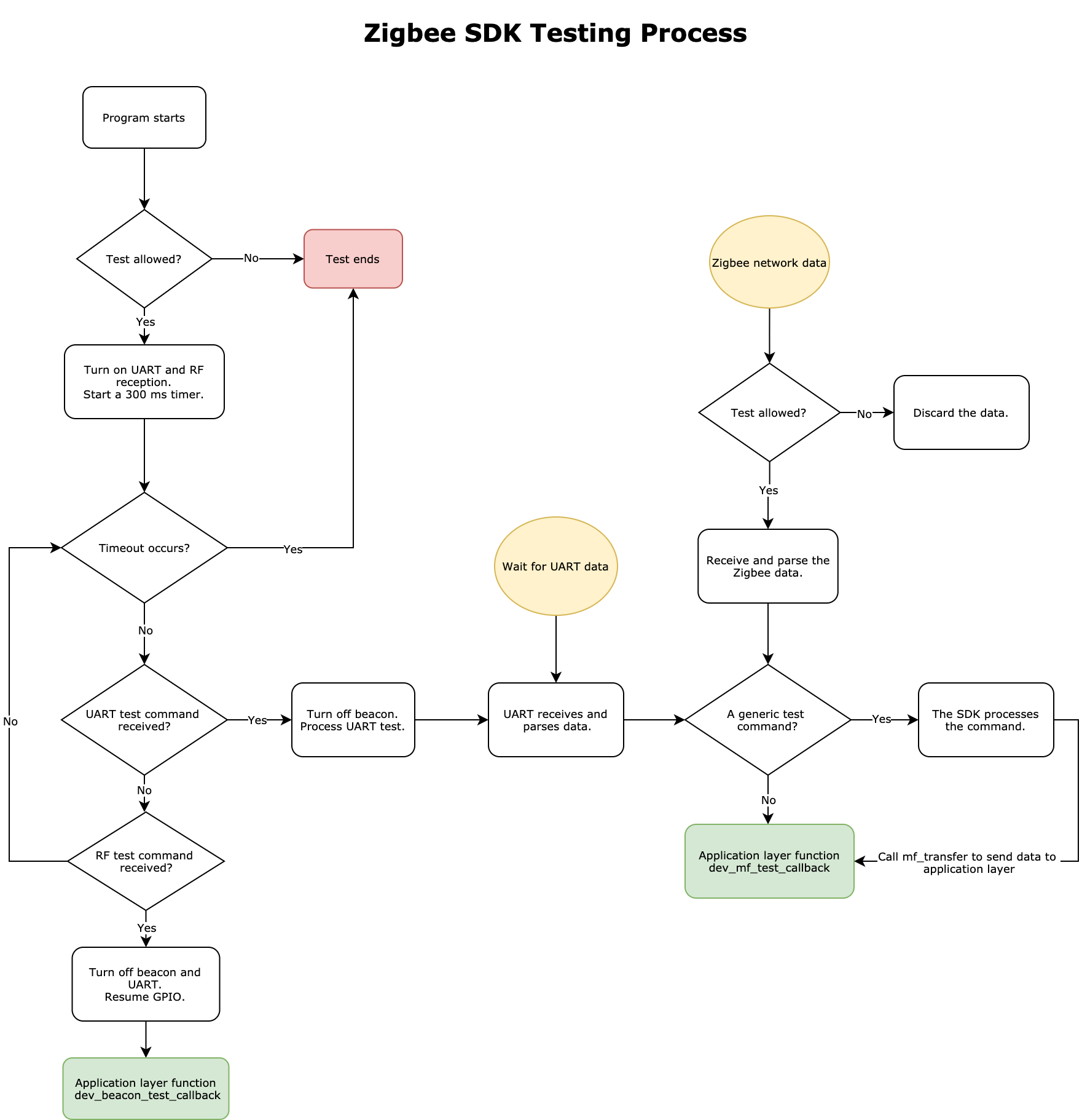
The code-based automated test is introduced to mass production for promoting efficiency, which is called production testing.
The SDK has implemented the functions for some testing items. For example, enter testing mode, read MAC address, detect firmware version, write PID, test RF performance, get RSSI value, and verify authorization, as shown in the following code snippet.
/**
 * @description: device manufactury test callback, when device is in manufactury test model,
 * sdk will use this callback to notify application the test item and test command;
 * @param {cmd} manufactury test type
 * @param {*args} manufactury test data
 * @param {arg_len} manufactury test data length
 * @return: none
 */
MF_TEST_RET_T dev_mf_test_callback(MF_TEST_CMD_T cmd, uint8_t *args, uint16_t arg_len)
{
    switch(cmd)
    {
        case MF_TEST_LED_ON_ALL:
        {
            dev_led_stop_blink(NET_LED_1_IO_INDEX, DEV_IO_ON);
            dev_led_stop_blink(LED_1_IO_INDEX, DEV_IO_ON);
            break;
        }
        case MF_TEST_LED_OFF_ALL:
        {
            dev_led_stop_blink(NET_LED_1_IO_INDEX, DEV_IO_OFF);
            dev_led_stop_blink(LED_1_IO_INDEX, DEV_IO_OFF);
            break;
        }
        case MF_TEST_LED_BLINK_ALL:
        {
            dev_led_start_blink(NET_LED_1_IO_INDEX, 500, 500, 4, DEV_IO_OFF);
            dev_led_start_blink(LED_1_IO_INDEX, 500, 500, 4, DEV_IO_OFF);
            break;
        }
        case MF_TEST_RELAY_ON_ALL:
        {
            dev_led_stop_blink(RELAY_1_IO_INDEX, DEV_IO_ON);
            break;
        }
        case MF_TEST_RELAY_OFF_ALL:
        {
            dev_led_stop_blink(RELAY_1_IO_INDEX, DEV_IO_OFF);
            break;
        }
        case MF_TEST_RELAY_BLINK_ALL:
        {
            dev_led_start_blink(RELAY_1_IO_INDEX, 500, 500, 4, DEV_IO_OFF);
            break;
        }
        case MF_TEST_BUTTON:
        {
            g_work_st = DEV_WORK_ST_TEST;
            return MF_TEST_DOING;
        }
        case MF_TRANSFER:
        {
        }
        default :
        {
            break;
        }
    }
    return MF_TEST_SUCCESS;
}
OTA firmware updates
The Zigbee module comes with the OTA update feature. After the firmware build is complete, you will get two types of output files. The .s37 file is used for flashing to the chip and the .bin file is used for OTA update deployment.
The device can update its firmware through the gateway. The update can be performed only if the update version is later than the installed version. You can upload the firmware updates to the Tuya Developer Platform and configure the OTA update deployment to send updates to end users.
-
For mains-powered routers, additional development work on the OTA update feature is not necessary.
-
For low power end devices, they are intended to sleep periodically, so the RF reception is turned off to save energy. After an update is initiated by the mobile app, the device should wake up to receive data and then process the update request in the following callback.
 // OTA update callback.
	void zg_ota_evt_callback(ZG_OTA_EVT_T evt)
	{
		 switch(evt) {
 		case ZG_OTA_EVT_START: { // Start the update.
 			zg_poll_interval_change( 250 ); //  You can set the data request interval to 250 ms to speed up the update process.
								zg_poll_start();
							break;
					}
					default: {
							zg_poll_interval_change( 1000 );
 			zg_poll_end(); // To save battery life, stop data request after the update is completed.
								break;
					}
		 }
	}
Is this page helpful?
YesFeedbackIs this page helpful?
YesFeedback


