PWM Driver
Overview
Pulse-width modulation (PWM) dimming controls the brightness of an LED by adjusting the relative ratios of the on time to the off time. When the switching frequency is greater than 100 Hz, the human eyes will average the on and off times, seeing only an effective brightness that is proportional to the LED’s on-time duty cycle. The more time the current is on, the brighter the LED appears to be.
Advantages
- Easy-to-implement. PWM dimming circuit is simple in structure. It can be made using very few peripheral components such as a PWM MOSFET driver.
- No chromaticity shift. The LED always works between full amplitude current and 0.
- Extremely high dimming accuracy. The pulse waveform can be controlled to a very high precision so it is easy to achieve a precision of one ten thousandth.
- No flicker. Even if the light is dimmed in a wide range, there will be no flicker. Because PWM dimming does not change the working conditions of the constant current source (boost ratio or step-down ratio), it is less likely that problems such as overheating will occur.
Things to note
- The choice of pulse frequency. The LED is in a fast switching state. If the operating frequency is very low, the human eye will feel flicker. To fully leverage the persistence of vision of the human eye, the operating frequency of the LED should be higher than 100 Hz, preferably 200 Hz.
- Avoiding noise from dimming. Typically, the switching frequency is in the 200 Hz to 20 kHz range where the human eye cannot detect the switching process between on and off state but can hear the noise from the inductances and output capacitors. There are two ways to solve this problem.
- One is to increase the switching frequency to above 20 kHz, falling out of the range of human hearing. But a very high frequency will cause some problems. The influence of various parasitic parameters can cause the pulse waveform (leading and trailing edges) to be distorted, which reduces the accuracy of dimming.
- The other way is to find out the noise-producing device and deal with it. Generally, it is the ceramic capacitor at the output end that generates audible noise. Ceramic capacitors are made of high dielectric constant ceramics, which have piezoelectric characteristics. Under the action of a 200 Hz pulse, the sound will be produced due to the mechanical vibration. The solution is to use tantalum capacitors instead. But tantalum capacitors with high withstand voltage are very expensive, which will increase some costs.
PWM driver solutions
2-channel white light dimming
There are two driver options you can choose from: cool and warm white dimming and correlated color temperature (CCT) dimming.
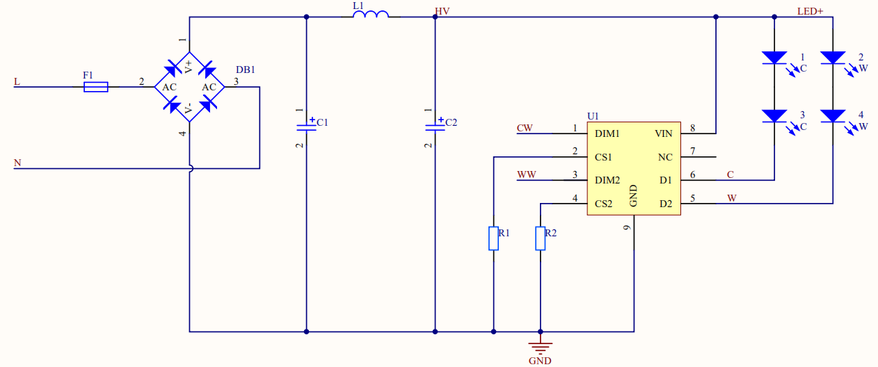
Cool and warm white dimming
Mix two channels of PWM signals to control the brightness and color temperature. The cool white (CW) channel controls the cool white dimming (high color temperature). The warm white (WW) channel controls the warm white dimming (low color temperature). The CW channel is used for single-channel dimming.
-
Complementary PWM output
As shown in the above circuit diagram, PG0 and PG1 are complementary. Such PWM circuit design can provide benefits for power supply circuits in LED applications.-
Advantages:
For PWM dimming mode, the MOSFET is on when the level is high. With the complementary PWM output applied, the outputs of the two channels cannot be high at the same time so drawing current from the input source will not happen. However, if you do not use the complementary output, the outputs of the two channels might be high at the same time. In this case, the two channels draw current from the input source at the same time. In terms of the power consumption, assume that one channel is 9W. The total power consumption when the two channels are both high equals the total output of 18W. Even if the average value is the same, the load on the input source is different. -
Things to note:
- The maximum power: Assume that the maximum PWM duty cycle of one channel is 100%. The total duty cycle for two complementary outputs should not exceed 100%. Otherwise, complementary outputs are not suitable for your application.
- No color temperature shift: If the power output of the cool and warm white light exceeds 100%, make sure the calculation of the color temperature for each channel is accurate.
-
-
Dead-band delay
In h-bridge PWM applications, if both the upper and lower power circuits are switched at the same time (one turned on, and the other turned off), both switches might be on for a short period of time due to delay in the circuitry. During this brief interval, a very high current (shoot-through current) will flow through both power switches, shorting the bridge supply.To avoid this potentially destructive shoot-through current from flowing during switching, dead-band delay can be implemented to allow one power circuit to be completely turned off before the other is turned on.
The shadow areas in the
PG0_DTandPG1_DTsignals denote the configured dead time. Dead-time delays the on signals for the switching devices. During the dead period, both upper and lower switching devices are turned off in order to prevent a short-circuit. Usually, the dead time is only a few percent of the duty cycle.
CCT dimming
The CCT dimming implements two channels for adjustment, one channel for brightness and the other one for color temperature.
As shown in the following circuit diagram, U1 (BP1371) and U2 (BP5926A) are LED drivers from Bright Power Semiconductor (BPS), used for brightness adjustment and color temperature respectively.
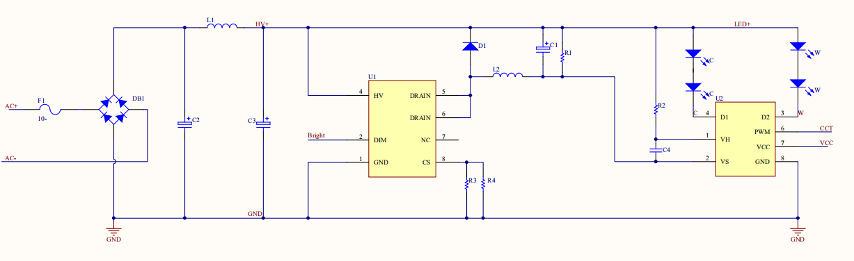
With built-in dual-channel 100V MOSFET, BP5926A provides high performance in the stepless color temperature adjustment. The light intensity ratio of the two channels can be adjusted by changing the duty cycle of the input PWM signal so that we can get the desired color temperature.
The outputs of the two PWM channels are complementary. The total current output remains unchanged during the color temperature adjustment, equaling the output of the constant current source.
The upper stage of the driver is charged and discharged as the capacitor is switched on and off. If the software cannot handle the process well, color temperature adjustment might cause flicker effects.
Make sure to observe the following principles when you work with the CCT driver:
- To adjust the brightness, you only change the PWM output of the brightness pin. To adjust the color temperature, you only change the PWM output of the CCT pin. If only one of the two channels is adjusted, the parameter of the channel unchanged should be left as is. Otherwise, flicker effects might occur.
- To turn off the light, do not send 0 to the two channels immediately but after 2,000 ms to let the capacitor be discharged completely.
- To unpair a light by physical operation, the CCT driver will set the brightness to 0 but keep the color temperature as is. Then, it waits for a specified time period (200 ms by default) to trigger the unpairing action.
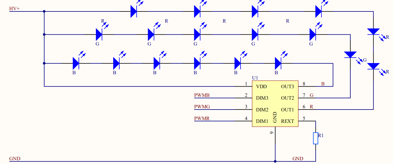
3-channel RGB light dimming
The module outputs signals from PWMR, PWMG, and PWMB channels. The linear constant current LED driver implements the constant output of RGB current.
Is this page helpful?
YesFeedbackIs this page helpful?
YesFeedback


