Product Solutions
This topic describes how to develop smart infrared (IR) products with the SoC-based no-code solution.
The no-code solution allows you to develop two types of IR products with local voice control, namely the IR remote voice control and the voice-enabled IR plug.
IR remote voice control
Features
The supported IR capabilities include IR signal transmission and reception, remote control matching, virtual remote control, and IR learning.
-
Voice control of IR devices
To enable voice control, the IR code library must have been downloaded to the local storage.
-
Scheduling by voice
Schedule a device to be turned off after a certain delay. When the timer fires, an IR command will be sent to the target IR device. The time interval can be set to 30 minutes or from 1 to 10 hours.
-
Voice wake-up
With voice control enabled, users should trigger the voice assistant with the wake word before giving voice commands.
-
Voice control of volume
Control the volume of an IR device with voice commands.
-
Change voice modes
The voice mode, voice wake-up mode, buzzer mode, and silent mode are supported. Users can change the mode with voice commands. The voice response can vary depending on the adopted mode.
Protocol
- Baud: 115200
- Data bit: 8
- Parity check: none
- Stop bit: 1
- Data flow control: none
- MCU: microcontroller unit. Your MCU communicates with Tuya’s modules through the serial port.
- Module: Tuya’s network module.
| Field | Length (byte) | Description |
|---|---|---|
| Header | 2 | It is fixed to 0x55aa. |
| Version | 1 | It is used for updates and extensions. |
| Command | 1 | Frame type |
| Data length | 2 | The length of data, in big-endian format. |
| Data | N | Entity data |
| Checksum | 1 | Start from the header, add up all the bytes, and then divide the sum by 256 to get the remainder. |
Description
-
All data greater than one byte is transmitted in big-endian format.
-
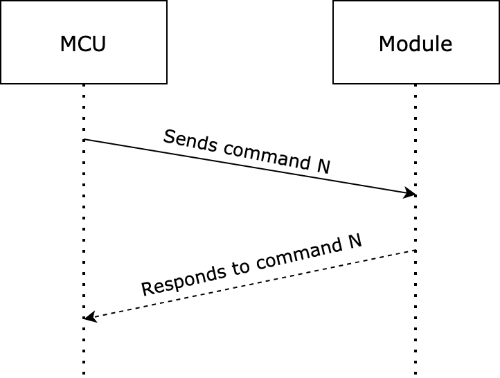
One command is sent by one party and received by the other party synchronously. That is, one party sends a command and waits for a response from the other party.
Report utterances
The voice-control MCU parses and converts the received utterance to the entry ID and sends the ID to the Wi-Fi module.
The following lists the voice control compatible categories.
Category ID
| Category ID | Product category name |
|---|---|
| 1 | Set-top box |
| 2 | TV |
| 3 | TV box |
| 4 | DVD (Not supported yet) |
| 5 | Air Conditioner |
| 6 | Projector |
| 7 | Speaker |
| 8 | Fan |
| 9 | DSLR camera |
| 10 | Light |
| 11 | Air purifier |
| 12 | Water heater |
Entry ID
Set-top box
| Entry ID | Command |
|---|---|
| 1 | Turn on set-top box |
| 2 | Turn off set-top box |
| 3 | Switch to live stream |
| 4 | Return to last screen |
| 5 | Channel up |
| 6 | Channel down |
| 7 | Up |
| 8 | Down |
| 8 | Left |
| 10 | Right |
| 11 | Confirm action |
| 12 | Volume up |
| 13 | Volume down |
| 14 | Open homepage |
TV
| Entry ID | Command |
|---|---|
| 1 | Turn on TV |
| 2 | Turn off TV |
| 3 | Up |
| 4 | Down |
| 5 | Left |
| 6 | Right |
| 7 | Confirm action |
| 8 | Volume up |
| 9 | Volume down |
| 10 | Return to last screen |
| 11 | Open homepage |
TV box
| Entry ID | Command |
|---|---|
| 1 | Turn on TV box |
| 2 | Turn off TV box |
| 3 | Volume up |
| 4 | Volume down |
| 5 | Up |
| 6 | Down |
| 7 | Left |
| 8 | Right |
| 9 | Confirm action |
| 10 | Return to last screen |
| 11 | Open homepage |
Air conditioner
| Entry ID | Command |
|---|---|
| 1 | Turn on air conditioner |
| 2 | Turn off air conditioner |
| 3 | Auto mode |
| 4 | Cool mode |
| 5 | Heat mode |
| 6 | Dry mode |
| 7 | Fan mode |
| 8 | Auto speed |
| 9 | High speed |
| 10 | Medium speed |
| 11 | Low speed |
| 12 | Fan speed up |
| 13 | Fan speed down |
| 14 | Temperature up |
| 15 | Temperature down |
| 16 | 15°C |
| 17 | 16°C |
| 18 | 17°C |
| 19 | 18°C |
| 20 | 19°C |
| 21 | 20°C |
| 22 | 21°C |
| 23 | 22°C |
| 24 | 23°C |
| 25 | 24°C |
| 26 | 25°C |
| 27 | 26°C |
| 28 | 27°C |
| 29 | 28°C |
| 30 | 29°C |
| 31 | 30°C |
| 32 | 31°C |
| 33 | 32°C |
| 34 | Start swing |
| 35 | Stop swing |
| 36 | Swing up and down |
| 37 | Stop swinging up and down |
| 38 | Swing left and right |
| 39 | Stop swinging left and right |
Projector
| Entry ID | Command |
|---|---|
| 1 | Turn on projector |
| 2 | Turn off projector |
| 3 | Up |
| 4 | Down |
| 5 | Left |
| 6 | Right |
| 7 | Confirm |
| 8 | Mute |
| 9 | Unmute |
| 10 | Volume up |
| 11 | Volume down |
Speaker
| Entry ID | Command |
|---|---|
| 1 | Turn on speaker |
| 2 | Turn off speaker |
| 3 | Volume up |
| 4 | Volume down |
| 5 | Play |
| 6 | Pause |
| 7 | Play last |
| 8 | Play next |
| 9 | Mute |
| 10 | Unmute |
| 11 | Fast forward |
| 12 | Stop |
Fan
| Entry ID | Command |
|---|---|
| 1 | Tun on fan |
| 2 | Turn off fan |
| 3 | Adjust oscillation |
| 4 | Adjust fan speed |
| 5 | Fan speed up |
| 6 | Fan speed down |
Light
| Entry ID | Command |
|---|---|
| 1 | Turn on light |
| 2 | Turn off light |
| 3 | Brightness up |
| 4 | Brightness down |
Air purifier
| Entry ID | Command |
|---|---|
| 1 | Turn on air purifier |
| 2 | Turn off air purifier |
| 3 | Auto mode |
| 4 | Turn off auto mode |
Water heater
| Entry ID | Command |
|---|---|
| 1 | Turn on water heater |
| 2 | Turn off water heater |
| 3 | Temperature up |
| 4 | Temperature down |
Parse utterances
After the voice control MCU recognizes an utterance for a category, it will send the utterance to the Wi-Fi module for parsing.
The MCU sends the following data.
| Field | Length (byte) | Description |
|---|---|---|
| Header | 2 | 0x55aa |
| Version | 1 | 0x03 |
| Command | 1 | 0x02 |
| Data length | 2 | 0x0005 |
| Data | 5 | |
| Checksum | 1 | Start from the header, add up all the bytes, and then divide the sum by 256 to get the remainder. |
The module returns the following data.
| Field | Length (byte) | Description |
|---|---|---|
| Header | 2 | 0x55aa |
| Version | 1 | 0x00 |
| Command | 1 | 0x02 |
| Data length | 2 | 0x0001 |
| Data | 1 | |
| Checksum | 1 | Start from the header, add up all the bytes, and then divide the sum by 256 to get the remainder. |
Query the category
The MCU uses this command to check if a category exists in the local library.
The MCU sends the following data.
| Field | Length (byte) | Description |
|---|---|---|
| Header | 2 | 0x55aa |
| Version | 1 | 0x03 |
| Command | 1 | 0x05 |
| Data length | 2 | 0x0001 |
| Data | 1 | Category ID |
| Checksum | 1 | Start from the header, add up all the bytes, and then divide the sum by 256 to get the remainder. |
The module returns the following data.
| Field | Length (byte) | Description |
|---|---|---|
| Header | 2 | 0x55aa |
| Version | 1 | 0x00 |
| Command | 1 | 0x05 |
| Data length | 2 | 0x0001 |
| Data | 1 | |
| Checksum | 1 | Start from the header, add up all the bytes, and then divide the sum by 256 to get the remainder. |
Report utterances for scheduling
Utterance ID for scheduling
| 1 | 30-minute timer |
|---|---|
| 2 | 1-hour timer |
| 3 | 2-hour timer |
| 4 | 3-hour timer |
| 5 | 4-hour timer |
| 6 | 5-hour timer |
| 7 | 6-hour timer |
| 8 | 7-hour timer |
| 9 | 8-hour timer |
| 10 | 9-hour timer |
| 11 | 10-hour timer |
After the voice-control MCU parses the received utterance, it reports the data to the Wi-Fi module to set a schedule.
The MCU sends the following data.
| Field | Length (byte) | Description |
|---|---|---|
| Header | 2 | 0x55aa |
| Version | 1 | 0x03 |
| Command | 1 | 0x03 |
| Data length | 2 | 0x0002 |
| Data | 2 | |
| Checksum | 1 | Start from the header, add up all the bytes, and then divide the sum by 256 to get the remainder. |
The module returns the following data.
| Field | Length (byte) | Description |
|---|---|---|
| Header | 2 | 0x55aa |
| Version | 1 | 0x00 |
| Command | 1 | 0x03 |
| Data length | 2 | 0x0001 |
| Data | 1 | |
| Checksum | 1 | Start from the header, add up all the bytes, and then divide the sum by 256 to get the remainder. |
The return value indicates whether the schedule is set successfully. If the IR code does not exist in the local library, the module also returns a failure result.
Cancel a schedule
After the voice-control MCU parses the received utterance, it reports the data to the Wi-Fi module to cancel a schedule.
The MCU sends the following data.
| Field | Length (byte) | Description |
|---|---|---|
| Header | 2 | 0x55aa |
| Version | 1 | 0x03 |
| Command | 1 | 0x06 |
| Data length | 2 | 0x0001 |
| Data | 1 | |
| Checksum | 1 | Start from the header, add up all the bytes, and then divide the sum by 256 to get the remainder. |
The module returns the following data.
| Field | Length (byte) | Description |
|---|---|---|
| Header | 2 | 0x55aa |
| Version | 1 | 0x00 |
| Command | 1 | 0x06 |
| Data length | 2 | 0x0001 |
| Data | 1 | |
| Checksum | 1 | Start from the header, add up all the bytes, and then divide the sum by 256 to get the remainder. |
The return value indicates whether the schedule is set successfully. If the IR code does not exist in the local library, the module also returns a failure result.
Report voice wake-up
When the MCU enters or exits the voice wake-up mode, it should notify the module of the current state to update the LED signal. The blue LED stays on or off to indicate entering or existing a voice mode.
The MCU sends the following data.
| Field | Length (byte) | Description |
|---|---|---|
| Header | 2 | 0x55aa |
| Version | 1 | 0x03 |
| Command | 1 | 0x04 |
| Data length | 2 | 0x0001 |
| Data | 1 | |
| Checksum | 1 | Start from the header, add up all the bytes, and then divide the sum by 256 to get the remainder. |
The module returns the following data.
| Field | Length (byte) | Description |
|---|---|---|
| Header | 2 | 0x55aa |
| Version | 1 | 0x00 |
| Command | 1 | 0x04 |
| Data length | 2 | 0x0001 |
| Data | 1 | |
| Checksum | 1 | Start from the header, add up all the bytes, and then divide the sum by 256 to get the remainder. |
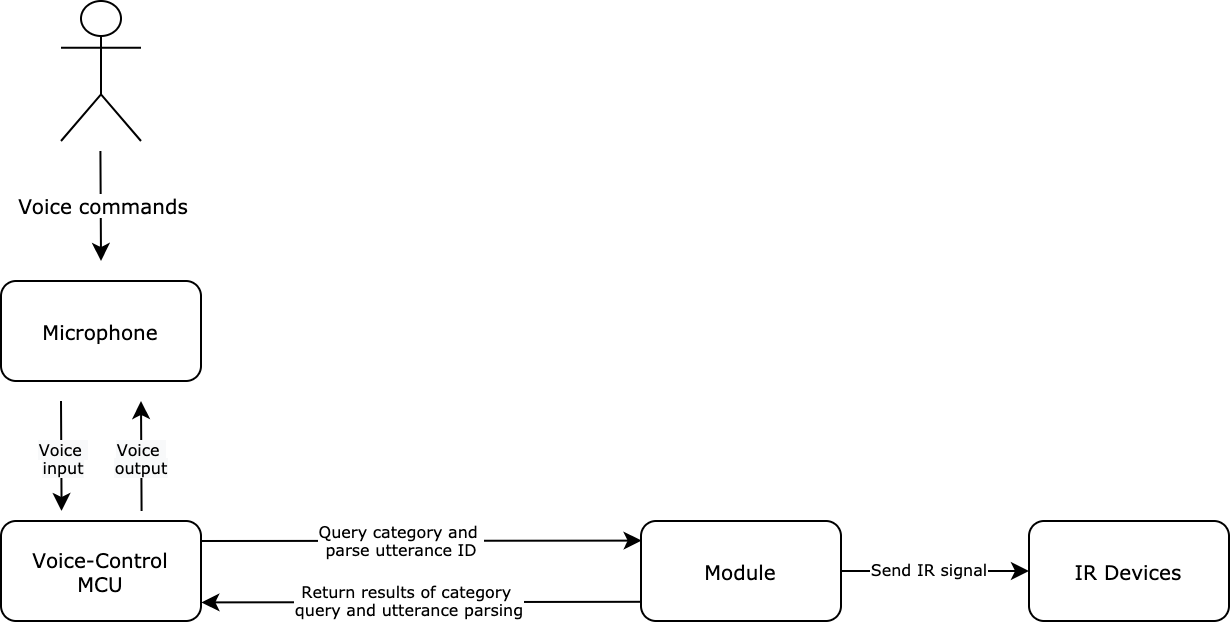
Interaction diagram
Voice-enabled IR plug
Features
The supported IR capabilities include control of IR devices, IR learning, and virtual remote control.
-
Device pairing by voice
Two approaches to pairing a device:
The utterance
start pairingcan activate pairing in EZ mode or over Bluetooth Low Energy. The utteranceAP pairingcan activate pairing in AP mode or over Bluetooth Low Energy. -
Voice wake-up
With voice control enabled, users should trigger the voice assistant with the wake word before giving voice commands.
-
Voice control of IR devices
To enable voice control, the IR code library must have been downloaded to the local storage. For air conditioners, the voice commands support the control of temperature, mode, and speed.
-
Scheduling by voice
Schedule a device to be turned off after a certain delay. When the timer fires, an IR command will be sent to the target IR device. The time interval can be set to 30 minutes or from 1 to 10 hours.
-
Voice control of volume
Control the volume of an IR device with voice commands.
Protocol
- Baud: 115200
- Data bit: 8
- Parity check: none
- Stop bit: 1
- Data flow control: none
- MCU: microcontroller unit. Your MCU communicates with Tuya’s modules through the serial port.
- Module: Tuya’s network module.
| Field | Length (byte) | Description |
|---|---|---|
| Header | 2 | It is fixed to 0x55aa. |
| Version | 1 | It is used for updates and extensions. |
| Command | 1 | Frame type |
| Data length | 2 | The length of data, in big-endian format. |
| Data | N | Entity data |
| Checksum | 1 | Start from the header, add up all the bytes, and then divide the sum by 256 to get the remainder. |
Device pairing by voice
The MCU sends the pairing command to the Wi-Fi module, and the Wi-Fi module returns the network status.
| Network status | Description | Status value | Description |
|---|---|---|---|
| Status 1 | EZ mode | 0x00 | The device is ready for pairing. |
| Status 2 | AP mode | 0x01 | The device is ready for pairing. |
| Status 3 | The Wi-Fi network is set up, but the device is not connected to the router. | 0x02 | The device is connecting to the network. |
| Status 4 | The Wi-Fi network is set up, and the device is connected to the router. | 0x03 | The device is connecting to the network. |
| Status 5 | The device is connected to the router and the cloud. | 0x04 | The device is paired. |
| Status 6 | The Wi-Fi device is in low power mode. | 0x05 | The device is not in the pairing mode. |
| Status 7 | If the module fails to connect to the cloud within three minutes, it will return a pairing failure. | 0x06 | Device pairing failed. |
The MCU sends the following data. For example, 55 aa 03 01 00 01 01 05.
| Field | Length (byte) | Description |
|---|---|---|
| Header | 2 | 0x55aa |
| Version | 1 | 0x03 |
| Command | 1 | 0x01 |
| Data length | 2 | 0x0001 |
| Data | 1 | |
| Checksum | 1 | Start from the header, add up all the bytes, and then divide the sum by 256 to get the remainder. |
The module returns the following data.
| Field | Length (byte) | Description |
|---|---|---|
| Header | 2 | 0x55aa |
| Version | 1 | 0x00 |
| Command | 1 | 0x01 |
| Data length | 2 | 0x0001 |
| Data | 1 | Indicates Wi-Fi status. Valid values:
|
| Checksum | 1 | Start from the header, add up all the bytes, and then divide the sum by 256 to get the remainder. |
Report utterances
The voice-control MCU parses and converts the received utterance to the entry ID and sends the ID to the Wi-Fi module.
The voice control feature only applies to air conditioners.
Category ID
| Category ID | Product category name |
|---|---|
| 5 | Air Conditioner |
Air Conditioner
| Entry ID | Command |
|---|---|
| 1 | Turn on air conditioner |
| 2 | Turn off air conditioner |
| 3 | Auto mode |
| 4 | Cool mode |
| 5 | Heat mode |
| 6 | Dry mode |
| 7 | Fan mode |
| 8 | Auto speed |
| 9 | High speed |
| 10 | Medium speed |
| 11 | Low speed |
| 12 | Fan speed up |
| 13 | Fan speed down |
| 14 | Temperature up |
| 15 | Temperature down |
| 16 | 15°C |
| 17 | 16°C |
| 18 | 17°C |
| 19 | 18°C |
| 20 | 19°C |
| 21 | 20°C |
| 22 | 21°C |
| 23 | 22°C |
| 24 | 23°C |
| 25 | 24°C |
| 26 | 25°C |
| 27 | 26°C |
| 28 | 27°C |
| 29 | 28°C |
| 30 | 29°C |
| 31 | 30°C |
| 32 | 31°C |
| 33 | 32°C |
| 34 | Start swing |
| 35 | Stop swing |
| 36 | Swing up and down |
| 37 | Stop swinging up and down |
| 38 | Swing left and right |
| 39 | Stop swinging left and right |
After the voice control MCU recognizes an utterance for a category, it will send the utterance to the Wi-Fi module for parsing.
The MCU sends the following data.
| Field | Length (byte) | Description |
|---|---|---|
| Header | 2 | 0x55aa |
| Version | 1 | 0x03 |
| Command | 1 | 0x02 |
| Data length | 2 | 0x0005 |
| Data | 5 | DATA[0]: The category ID. DATA[1] to DATA[4]: The entry ID. |
| Checksum | 1 | Start from the header, add up all the bytes, and then divide the sum by 256 to get the remainder. |
The module returns the following data.
| Field | Length (byte) | Description |
|---|---|---|
| Header | 2 | 0x55aa |
| Version | 1 | 0x00 |
| Command | 1 | 0x02 |
| Data length | 2 | 0x0001 |
| Data | 1 | 1: The utterance is matched. 0: The utterance is not matched. |
| Checksum | 1 | Start from the header, add up all the bytes, and then divide the sum by 256 to get the remainder. |
Query the category
The MCU uses this command to check if a category exists in the local library.
The MCU sends the following data.
| Field | Length (byte) | Description |
|---|---|---|
| Header | 2 | 0x55aa |
| Version | 1 | 0x03 |
| Command | 1 | 0x05 |
| Data length | 2 | 0x0001 |
| Data | 1 | Category ID |
| Checksum | 1 | Start from the header, add up all the bytes, and then divide the sum by 256 to get the remainder. |
The module returns the following data.
| Field | Length (byte) | Description |
|---|---|---|
| Header | 2 | 0x55aa |
| Version | 1 | 0x00 |
| Command | 1 | 0x05 |
| Data length | 2 | 0x0001 |
| Data | 1 | 1: The category exists. 0: The category does not exist. |
| Checksum | 1 | Start from the header, add up all the bytes, and then divide the sum by 256 to get the remainder. |
Report utterances for scheduling
Utterance ID for scheduling
| 1 | 30-minute timer |
|---|---|
| 2 | 1-hour timer |
| 3 | 2-hour timer |
| 4 | 3-hour timer |
| 5 | 4-hour timer |
| 6 | 5-hour timer |
| 7 | 6-hour timer |
| 8 | 7-hour timer |
| 9 | 8-hour timer |
| 10 | 9-hour timer |
| 11 | 10-hour timer |
After the voice-control MCU parses the received utterance, it reports the data to the Wi-Fi module to set a schedule.
The MCU sends the following data.
| Field | Length (byte) | Description |
|---|---|---|
| Header | 2 | 0x55aa |
| Version | 1 | 0x03 |
| Command | 1 | 0x03 |
| Data length | 2 | 0x0002 |
| Data | 2 | |
| Checksum | 1 | Start from the header, add up all the bytes, and then divide the sum by 256 to get the remainder. |
The module returns the following data.
| Field | Length (byte) | Description |
|---|---|---|
| Header | 2 | 0x55aa |
| Version | 1 | 0x00 |
| Command | 1 | 0x03 |
| Data length | 2 | 0x0001 |
| Data | 1 | |
| Checksum | 1 | Start from the header, add up all the bytes, and then divide the sum by 256 to get the remainder. |
The return value indicates whether the schedule is set successfully. If the IR code does not exist in the local library, the module also returns a failure result.
Cancel a schedule
After the voice-control MCU parses the received utterance, it reports the data to the Wi-Fi module to cancel a schedule.
The MCU sends the following data.
| Field | Length (byte) | Description |
|---|---|---|
| Header | 2 | 0x55aa |
| Version | 1 | 0x03 |
| Command | 1 | 0x06 |
| Data length | 2 | 0x0001 |
| Data | 1 | |
| Checksum | 1 | Start from the header, add up all the bytes, and then divide the sum by 256 to get the remainder. |
The module returns the following data.
| Field | Length (byte) | Description |
|---|---|---|
| Header | 2 | 0x55aa |
| Version | 1 | 0x00 |
| Command | 1 | 0x06 |
| Data length | 2 | 0x0001 |
| Data | 1 | |
| Checksum | 1 | Start from the header, add up all the bytes, and then divide the sum by 256 to get the remainder. |
The return value indicates whether the schedule is set successfully. If the IR code does not exist in the local library, the module also returns a failure result.
Report voice wake-up
When the MCU enters or exits the voice wake-up mode, it should notify the module of the current state to update the LED signal. The blue LED stays on or off to indicate entering or existing a voice mode.
The MCU sends the following data.
| Field | Length (byte) | Description |
|---|---|---|
| Header | 2 | 0x55aa |
| Version | 1 | 0x03 |
| Command | 1 | 0x04 |
| Data length | 2 | 0x0001 |
| Data | 1 | |
| Checksum | 1 | Start from the header, add up all the bytes, and then divide the sum by 256 to get the remainder. |
The module returns the following data.
| Field | Length (byte) | Description |
|---|---|---|
| Header | 2 | 0x55aa |
| Version | 1 | 0x00 |
| Command | 1 | 0x04 |
| Data length | 2 | 0x0001 |
| Data | 1 | |
| Checksum | 1 | Start from the header, add up all the bytes, and then divide the sum by 256 to get the remainder. |
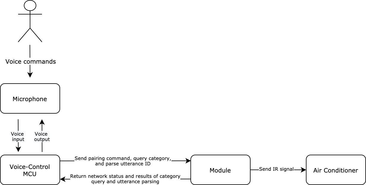
Interaction diagram
Is this page helpful?
YesFeedbackIs this page helpful?
YesFeedback


