Zigbee Generic Interfaces
Overview
If your product cannot work with the Zigbee standard protocol, you can use the generic interfaces to enable it to connect to the Tuya Developer Platform. The Zigbee module acts as a mediator that connects the MCU and the Zigbee gateway. It converts the data received from the gateway into a format defined in Tuya-specific serial communication protocol and sends the converted data to the MCU through the serial port. In the other direction, the Zigbee module converts the data received from the MCU into the format defined in the Zigbee Cluster Library (ZCL) and sends the converted data to the gateway that exchanges data with the cloud. In a nutshell, you can use the Zigbee network to connect the MCU to cloud services and thus make your product IoT-enabled.

Zigbee specification
Zigbee basics
| Parameter | Value |
|---|---|
| Profile ID | 0x0104 |
| Device ID | 0x0051 |
| Endpoint | Description |
|---|---|
| 1 | The endpoint used for application data exchange. |
Clusters, attributes, and commands
| SMART_PLUG (0x0051) | |
|---|---|
| Input clusters (server) | Output clusters (client) |
| Basic (0x0000) | OTA upgrade (0x0019) |
| Time (0x000A) | / |
| Private cluster (0XEF00) | / |
Basic cluster
Attributes:
| ID | Name | Data type (ID) | Range | Default |
|---|---|---|---|---|
| 0x0000 | ZCLVersion | uint8 (0x20) | 0x00 to 0xff | 0x03 |
| 0x0001 | ApplicationVersion | uint8 (0x20) | 0x00 to 0xff | For example, 0b 01 00 0001 indicates 1.0.1, that is, 0x41 represents version 1.0.1. This attribute is used for OTA updates. When an OTA update is initiated, the gateway reads the version number of the update and pushes it to the Zigbee device. After the Zigbee device is restarted after the update, the gateway reads the current version to check for the update result. The firmware can only be updated to a higher version. |
| 0x0002 | StackVersion | uint8 (0x20) | 0x00 to 0xff | 0x02 |
| 0x0003 | HWVersion | uint8 (0x20) | 0x00 to 0xff | 0x01 |
| 0x0004 | ManufacturerName | string (0x42) | 0 to 32 bytes | The value of this attribute is 16 bytes in length, consisting of 8-byte prefix and 8-byte PID. 0 to 7 bytes: _TZE600_. 8 to 16 bytes: The PID, the unique identifier of the Zigbee product you create on the Tuya Developer Platform. |
| 0x0005 | ModelIdentifier | string (0x42) | 0 to 32 bytes | TS0105, used for the gateway to identify the device type. |
| 0x0007 | PowerSource | enum8 (0x30) | 0x00 to 0xff | It depends on your product. |
| 0xfffd | ClusterRevision | uint16 (0x21) | 0x0000 to 0xffff | 0x0001 |
Commands
| ID | Name | Direction | Description |
|---|---|---|---|
| 0x00 | Reset to factory default | Client to server | C: Stands for client. S: Stands for server. |
Private cluster
To achieve the communication between the Zigbee module and the MCU, use the private cluster to define a class of private cluster commands to transmit data.
In the application support sublayer (APS):
- Destination Endpoint: 0x01
- Cluster ID: 0xEF00
- Profile ID: 0x0104
- Source Endpoint: 0x01
In the ZCL layer, the private command ID is used to identify commands. Define private frame in the ZCL payload in the format sequence number (2 bytes) + data point (DP) data.
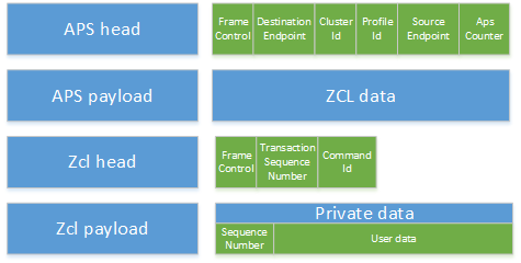
The following table lists the ZCL header format.
| Field | Length (bit) | Value | Description |
|---|---|---|---|
| Frame type | 2 | 01 | Command is specific to a cluster. |
| Manufacturer specific | 1 | 0 | The manufacturer code field is not included in the ZCL frame. |
| Direction | 1 | 0/1 | 0: Gateway to Zigbee device. 1: Zigbee device to gateway. |
| Disable default response | 1 | 0/1 | It defaults to 1. It is set to 0 only when the Zigbee device proactively reports data to the gateway. The gateway returns a response to indicate successful reporting. |
| Reserved | 3 | 000 | Reserved |
Private command ID
| Command enumerations | Value | Description |
|---|---|---|
| TY_DATA_REQUEST | 0x00 | The gateway sends a data request to the Zigbee device. |
| TY_DATA_RESPONE | 0x01 | The MCU responds to a data request. |
| TY_DATA_REPORT | 0x02 | The MCU proactively reports data to the gateway. This is two-way communication. |
| TY_DATA_QUERY | 0x03 | The gateway sends a query to the Zigbee device for all the current information. The query does not contain a ZCL payload. We recommend that you set a reporting policy on the Zigbee device to avoid reporting all data in one task. |
| TUYA_MCU_VERSION_REQ | 0x10 | The gateway sends a query to the Zigbee module for the MCU firmware version. |
| TUYA_MCU_VERSION_RSP | 0x11 | The Zigbee module returns the MCU firmware version, or the MCU proactively reports its firmware version. |
| TUYA_MCU_OTA_NOTIFY | 0x12 | The gateway notifies the Zigbee module of MCU firmware updates. |
| TUYA_OTA_BLOCK_DATA_REQ | 0x13 | The Zigbee module requests to download the MCU firmware update. |
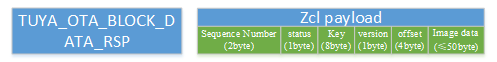
| TUYA_OTA_BLOCK_DATA_RSP | 0x14 | The gateway returns the update package to the Zigbee module. |
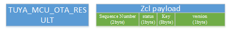
| TUYA_MCU_OTA_RESULT | 0x15 | The Zigbee module returns the result of MCU firmware updates to the gateway. |
| TUYA_MCU_SYNC_TIME | 0x24 | Time synchronization (two-way) |
Frame of command ID
-
TY_DATA_ REQUESTandTY_DATA_RESPONEare used to send DP data from the gateway to the Zigbee device. Then, the Zigbee device sends the received data to the MCU through serial communication. The MCU returns a response after it executes the received command. The Zigbee module then converts the received data into aTY_DATA_RESPONEresponse to the gateway.
-
The Zigbee module uses the command
TY_DATA_REPORTto proactively report the status changes to the gateway. The gateway returns a response through the same command on receiving the data.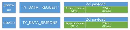
-
Request MCU version


-
MCU OTA update
-
Time synchronization
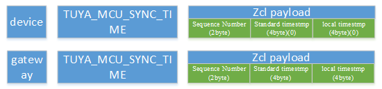
DP data format
| Data segment | Length (byte) | Description | |||
|---|---|---|---|---|---|
| DPID | 1 | The ID of a DP. | |||
| type | It indicates the specific data type of a DP defined on the Tuya Developer Platform, which is represented by the Value. | ||||
| Type | Value | Length (byte) | Description | ||
| Raw | 0x00 | N | Represents a DP of raw data type. The data is passed through the module to the cloud. | ||
| Boolean | 0x01 | 1 | The valid values are 0x00 and 0x01. | ||
| Value | 0x02 | 4 | Represents a DP of integer data type, in big-endian format. | ||
| String | 0x03 | N | Represents a DP of string data type. | ||
| Enum | 0x04 | 1 | Represents a DP of enum data type, ranging from 0 to 255. | ||
| Bitmap | 0x05 | 1/2/4 | Data greater than one byte is transmitted in big-endian format. | ||
| len | 2 | The length is the number of bytes of a value. | |||
| Value | 1/2/4/N | Represented in hexadecimal format. Data greater than one byte is transmitted in big-endian format. | |||
Over the Air Upgrade
Attributes:
| ID | Name | Data type (ID) | Range | Default |
|---|---|---|---|---|
| 0x0000 | UpgradeServerID | EUI64 (0xF0) | / | 0xffffffffffffffff |
| 0x0001 | FileOffset | uint32 (0x23) | / | 0x00000000 |
| 0x0002 | CurrentFileVersion | uint32 (0x23) | / | 0x21050002 |
| 0x0006 | ImageUpgradeStatus | enum8 (0x30) | / | 0x00 |
| 0x0007 | Manufacturer ID | uint16 (0x21) | / | 0x1168 |
| 0x0008 | Image Type ID | uint16 (0x21) | / | 0x80f6 |
| 0x0009 | MinimumBlockPeriod | uint16 (0x21) | / | 0x0000 |
| 0xfffd | ClusterRevision | int16 (0x29) | 0x0000 to 0xffff | 0x0001 |
Commands
| ID | Name | Direction |
|---|---|---|
| 0x00 | Image Notify | Server to client |
| 0x01 | Query Next Image Request | Client to server |
| 0x03 | Image Block Request | Client to server |
| 0x06 | Upgrade End Request | Client to server |
Serial communication protocol
A frame for serial communication comprises header (front), version (ver), command (cmd), data length (length), data (data), and checksum (check).
The frame is formatted as illustrated in the following table:
| Octets: 2 | 1 | 2 | 1 | 2 | Variable | 1 |
|---|---|---|---|---|---|---|
| Front | Ver | Seq | Cmd | Length | Data | Check |
Frame format description
| Field | Description |
|---|---|
| Header (front) | A 2-byte leader character, fixed to 0x55aa. |
| Version (ver) | The version of the serial protocol, used for protocol updates or extensions. |
| Sequence number (seq) | The transmission sequence number, ranging from 0 to 65535. This counter shall wrap to zero after 65535. |
| Command (cmd) | See the following table for specific serial communication commands. |
| Data length (length) | The payload length. The length of a single frame must not exceed 64 bytes. |
| Data (data) | The payload data. |
| Checksum (check) | Start from the header, add up all the bytes, and then divide the sum by 256 to get the remainder. |
Serial communication commands
| Command ID | Description |
|---|---|
| 0x01 | Query or report product information. |
| 0x02 | Query or report device status. |
| 0x03 | Reset a Zigbee device. |
| 0x04 | Send commands |
| 0x05 | Report status. |
| 0x06 | Query status. |
| 0x07 | Reserved |
| 0x08 | Test the Zigbee device functionality. |
| 0x09 | Query the key information, used for scene switches only. |
| 0x0A | Wake up a scene, used for scene switches only. |
| 0x0A to 0x23 | Reserved |
| 0x24 | Time synchronization |
Is this page helpful?
YesFeedbackIs this page helpful?
YesFeedback


