L610 Serial Communication Protocol
Terms
- Module: refers to the L610 Cat.1 module in this topic.
- DP: stands for data point. Each feature defined for a product on the Tuya Developer Platform is described as a DP.
Serial communication
- Baud rate: 115200 or 9600. The baud rate will be automatically detected for two minutes. If not specified, the default baud rate of 115200 will be used.
- Data bit: 8
- Parity check: none
- Stop bit: 1
- Data flow control: none
- MCU: microcontroller unit. Your MCU communicates with Tuya’s modules through the serial port.
Frame format
| Field | Length (byte) | Description |
|---|---|---|
| Header | 2 | It is fixed to 0x55aa. |
| Version | 1 | It is used for updates and extensions. |
| Command | 1 | The frame type. |
| Data length | 2 | Big-endian format. |
| Data | N | The payload. |
| Checksum | 1 | Start from the header, add up all the bytes, and then divide the sum by 256 to get the remainder. |
-
All data greater than one byte is transmitted in big-endian format.
-
Typically, one command is sent by one party and received by the other party synchronously. That is, one party sends a command and waits for a response from the other party. If the sender does not receive a correct response packet within a specified time period, the transmission times out, as shown in the following figure.
For more information, see the Protocol list.
-
Both command sending and status reporting use asynchronous transmission. Assume that the module sends a control command
Xand the MCU reports statusY. The data transmission is performed as shown below.
-
The MCU reports status:
Protocol list
Heartbeat check
- The module sends heartbeats to the MCU every 15 seconds. If the MCU does not respond within the 90-second timeout period, the module considers a communication exception occurred and will restart the software.
- The MCU can determine whether the module works properly according to the heartbeat. If the module does not send heartbeats at regular intervals, the MCU can use the reset pin to reset the module.
The module sends the following data.
| Field | Length (byte) | Description |
|---|---|---|
| Header | 2 | It is fixed to 0x55aa. |
| Version | 1 | 0x00 |
| Command | 1 | 0x00 |
| Data length | 2 | 0x0000 |
| Data | 0 | None |
| Checksum | 1 | Start from the header, add up all the bytes, and then divide the sum by 256 to get the remainder. |
For example, 0x55aa 00 00 0000 ff
The MCU returns the following data.
| Field | Length (byte) | Description |
|---|---|---|
| Header | 2 | It is fixed to 0x55aa. |
| Version | 1 | 0x00 |
| Command | 1 | 0x00 |
| Data length | 2 | 0x0000 |
| Data | 1 | 0x00: The MCU returns this value only one time after a restart. The module uses this value to determine whether the MCU restarts during operation. 0x01: The MCU returns this value except for the first response after a restart. |
| Checksum | 1 | Start from the header, add up all the bytes, and then divide the sum by 256 to get the remainder. |
Example:
- The MCU returns
0x55aa 03 00 0001 00 03after a restart. - The MCU returns
0x55aa 03 00 0001 01 04except for the first response after a restart.
Query product information
- Product ID (PID): a unique identifier assigned to each product created on the Tuya Developer Platform for storing product information in the cloud.
- Product information consists of the product ID and the MCU software version number.
- MCU software version number: It is expressed in dot-decimal notation
x.x.xwherexis a decimal digit between 0 and 99.
The module sends the following data.
| Field | Length (byte) | Description |
|---|---|---|
| Header | 2 | It is fixed to 0x55aa. |
| Version | 1 | 0x00 |
| Command | 1 | 0x01 |
| Data length | 2 | 0x0000 |
| Data | 0 | None |
| Checksum | 1 | Start from the header, add up all the bytes, and then divide the sum by 256 to get the remainder. |
For example, 0x55aa 00 00 0000 ff
The MCU returns the following data.
| Field | Length (byte) | Description |
|---|---|---|
| Header | 2 | It is fixed to 0x55aa. |
| Version | 1 | 0x03 |
| Command | 1 | 0x01 |
| Data length | 2 | N |
| Data | N | {"p":"AIp08kLIftb8x2x0", "v":"1.0.0", "m":1, "apn":"cniot", "mht":60, "qr":1 } The apn (access point name) is optional. If not specified, the system will configure the APN settings automatically. mht and qr are optional. |
| Checksum | 1 | Start from the header, add up all the bytes, and then divide the sum by 256 to get the remainder. |
For example, {"p":"AIp08kLIftb8x2x0","v":"1.0.0","m":1}
pindicates the PID isAIp08kLIftb8x2x0.vindicates the MCU version is 1.0.0.mindicates the power consumption of the module.0: standard power.1: low power. Note that the period of the TuyaOS timer is one second.
mhtindicates the MQTT heartbeat interval for the module, in seconds. The default value is 100 seconds.qrspecifies whether to pull the short URL of the QR code for pairing.1: Pull the short URL.0: Not pull the short URL. If a device has been paired, the short URL will not be pulled.
Query working mode
- The working mode indicates how the network status is indicated and the way to trigger module reset. Theoretically, the module can work in the following two modes:
- The module works with the MCU to process network events. Through serial communication, the module sends the network status to the MCU for LED indication. The MCU can send a command to reset the module when necessary.
- The module processes network events itself (not supported). The
NET_MODEpin on the module drives the LED indicator to indicate the network status. The GPIO input signal determines module reset.
- When the module detects a low level on the reset pin for more than three seconds, it will trigger a reset action. The following command specifies the GPIO pins of the LED indicator and the reset button. This feature is not available in low power mode.
In the module self-processing mode, the LED indicator can only be defined by NET_MODE.
The module sends the following data.
| Field | Length (byte) | Description |
|---|---|---|
| Header | 2 | It is fixed to 0x55aa. |
| Version | 1 | 0x00 |
| Command | 1 | 0x02 |
| Data length | 2 | 0x0000 |
| Data | 0 | None |
| Checksum | 1 | Start from the header, add up all the bytes, and then divide the sum by 256 to get the remainder. |
For example, 0x55aa 00 02 0000 01
The MCU returns the following data.
| Field | Length (byte) | Description |
|---|---|---|
| Header | 2 | It is fixed to 0x55aa. |
| Version | 1 | 0x03 |
| Command | 1 | 0x02 |
| Data length | 2 | 0x0000: The module works with the MCU to process network events. 0x0002: The module processes network events itself. |
| Data | 0/2 | The data length is 2 bytes.
|
| Checksum | 1 | Start from the header, add up all the bytes, and then divide the sum by 256 to get the remainder. |
Example:
- The module works with the MCU to process network events:
0x55aa 03 02 0000 04is returned. - The module processes network events itself:
0x55aa 03 02 0002 0c0d 1fis returned.0x0cindicates the LED indicator is connected to GPIO12.0x0dindicates the reset button is connected to GPIO13.
Report network status
| Network status | Description | Status value |
|---|---|---|
| Status 1 | The SIM card is not connected. | 0x00 |
| Status 2 | Search for cellular networks. | 0x01 |
| Status 3 | The module is registered with the cellular network but not connected to the network. | 0x02 |
| Status 4 | The module is connected to the network and gets an IP address. | 0x03 |
| Status 5 | The module is connected to the cloud. | 0x04 |
| Status 6 | SIM card registration is denied, which might be because it is not subscribed to a cellular service provider. | 0x05 |
- When the module detects that the MCU is restarted or reconnected, it will proactively send the current network status to the MCU.
- When the network status of the module changes, the module will proactively send its current status to the MCU.
- If you choose the module self-processing mode, implementing this protocol for your MCU is not necessary.
The module sends the following data.
| Field | Length (byte) | Description |
|---|---|---|
| Header | 2 | It is fixed to 0x55aa. |
| Version | 1 | 0x00 |
| Command | 1 | 0x03 |
| Data length | 2 | 0x0001 |
| Data | 1 | See the description of network status. |
| Checksum | 1 | Start from the header, add up all the bytes, and then divide the sum by 256 to get the remainder. |
For example, 0x55aa 00 03 0001 00 03
The MCU returns the following data.
| Field | Length (byte) | Description |
|---|---|---|
| Header | 2 | It is fixed to 0x55aa. |
| Version | 1 | 0x00 |
| Command | 1 | 0x03 |
| Data length | 2 | 0x0000 |
| Data | 0 | None |
| Checksum | 1 | Start from the header, add up all the bytes, and then divide the sum by 256 to get the remainder. |
For example, 0x55aa 03 03 0000 05
Reset module
After the Cat.1 module receives the reset command, it will reset the SIM card and then reconnect to the cellular network.
The MCU sends the following data.
| Field | Length (byte) | Description |
|---|---|---|
| Header | 2 | 0x55aa |
| Version | 1 | 0x03 |
| Command | 1 | 0x04 |
| Data length | 2 | 0x0000 |
| Data | 0 | None |
| Checksum | 1 | Start from the header, add up all the bytes, and then divide the sum by 256 to get the remainder. |
For example, 0x55aa 03 04 0000 06
The module returns the following data.
| Field | Length (byte) | Description |
|---|---|---|
| Header | 2 | 0x55aa |
| Version | 1 | 0x03 |
| Command | 1 | 0x04 |
| Data length | 2 | 0x0000 |
| Data | 0 | None |
| Checksum | 1 | Start from the header, add up all the bytes, and then divide the sum by 256 to get the remainder. |
Example: 0x55aa 00 04 0000 03
Set cellular mode
The Cat.1 module can work in fully operational mode or airplane mode.
Do not set the cellular mode repeatedly. Otherwise, the module can return a failure.
The MCU sends the following data.
| Field | Length (byte) | Description |
|---|---|---|
| Header | 2 | 0x55aa |
| Version | 1 | 0x03 |
| Command | 1 | 0x05 |
| Data length | 2 | 0x0001 |
| Data | 1 | 1: fully-operational mode. 4: airplane mode. |
| Checksum | 1 | Start from the header, add up all the bytes, and then divide the sum by 256 to get the remainder. |
For example, 0x55aa 03 04 0000 06
The module returns the following data.
| Field | Length (byte) | Description |
|---|---|---|
| Header | 2 | 0x55aa |
| Version | 1 | 0x00 |
| Command | 1 | 0x05 |
| Data length | 2 | 0x0000 |
| Data | 1 | 0: Cellular mode is set successfully. 1: Failed to set cellular mode. |
| Checksum | 1 | Start from the header, add up all the bytes, and then divide the sum by 256 to get the remainder. |
Example: 0x55aa 00 04 0000 03
Send commands
The module sends the following data.
| Field | Length (byte) | Description |
|---|---|---|
| Header | 2 | 0x55aa |
| Version | 1 | 0x00 |
| Command | 1 | 0x06 |
| Data length | 2 | It depends on the number of data units. |
| Data | N | See the description of data units below. |
| Checksum | 1 | Start from the header, add up all the bytes, and then divide the sum by 256 to get the remainder. |
Description of data units
The following table lists the format and type of data units.
| Field | Length | Description |
|---|---|---|
| dpid | 1 | The ID of DP. |
| type | 1 | The data type of DP. |
| len | 2 | Data length |
| Value | 1/2/4/N | The payload, in big-endian format. |
Description of data types
| Data type ID | Type | Length | Description |
|---|---|---|---|
| 0x00 | Raw | N | Raw data type. |
| 0x01 | Boolean | 1 | Boolean data type. A Boolean value is either 0 or 1. |
| 0x02 | Value | 4 | Integer data type. |
| 0x03 | String | N | String data type. |
| 0x05 | Enum | 1 | Enumeration data type. |
| 0x06 | Bitmap | 1/2/4 | Bitmap data type. |
Report status
- For more information about the DP data unit, see data unit.
- This is an asynchronous command. The MCU uses it to report device status to the module, which can be triggered by three mechanisms.
- After the MCU executes the command received from the module, it reports the changed DP status to the module.
- When the MCU proactively detects status changes of DPs, it reports the changed DP status to the module.
- When the MCU receives the DP status query, it sends the status of all DPs to the module.
- The MCU can report the status of multiple DPs.
The MCU sends the following data.
| Field | Length (byte) | Description |
|---|---|---|
| Header | 2 | 0x55aa |
| Version | 1 | 0x00 |
| Command | 1 | 0x06 |
| Data length | 2 | It depends on the number of data units. |
| Data | N | See the description of data units. |
| Checksum | 1 | Start from the header, add up all the bytes, and then divide the sum by 256 to get the remainder. |
Suppose that DP 5 of a value type describes the humidity. When the current humidity is 30%, the MCU reports the following data.
0x55aa 03 07 0008 05 02 0004 0000001e 3a
Query status
- The module asynchronously queries the status of all object DPs. When the MCU receives queries, it sends the status of DPs to the module through reporting status.
- The module sends a status query to the MCU when the following two events occur.
- When powered on for the first time, the module sends a status query after it connects to the MCU and the Tuya Developer Platform.
- When the module detects the MCU is restarted or disconnected and then goes online, the module sends a status query.
The module sends the following data.
| Field | Length (byte) | Description |
|---|---|---|
| Header | 2 | 0x55aa |
| Version | 1 | 0x00 |
| Command | 1 | 0x08 |
| Data length | 2 | 0x0000 |
| Data | 0 | None |
| Checksum | 1 | Start from the header, add up all the bytes, and then divide the sum by 256 to get the remainder. |
Example: 0x55aa 00 08 0000 07
Update MCU firmware
-
You can specify the update method for OTA firmware update. The module only serves as the channel for OTA data transmission, without any data parsing operation.
-
The Tuya Developer Platform provides four update methods.
- Update notification: Users receive a firmware update notification on the app and choose whether to install updates.
- Automatic update: Users will not receive any update pop-up window. The module checks for firmware updates within one minute after power-on. If any new version is available, it will automatically pull the updates. The module checks for updates every 24 hours after the first-time power-on.
- Forced update: Users receive a firmware update notification on the app and have no option but to update the firmware.
- Check for updates: Users will not receive a firmware update notification on the app but need to manually check for new updates.
-
After the module has sent all update packets, it will send the command
0x01to request the product information. The MCU must reply with the new MCU firmware version number within one minute. The new version number should be consistent with that configured on the Tuya Developer Platform.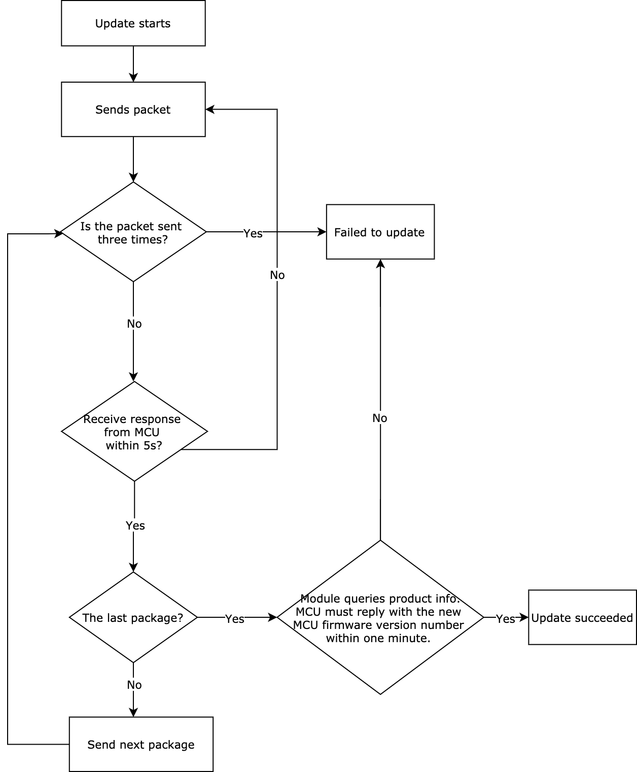
Start OTA update
The OTA update can be initiated automatically or manually. For automatic updates, when the module detects MCU firmware updates from the cloud, the transmission of the update package automatically starts. For manual updates, the module initiates updates only when updates are confirmed on the app.
The module sends the following data.
| Field | Length (byte) | Description |
|---|---|---|
| Header | 2 | 0x55aa |
| Version | 1 | 0x00 |
| Command | 1 | 0x0a |
| Data length | 2 | 0x0004 |
| Data | 4 | The size of the update package. |
| Checksum | 1 | Start from the header, add up all the bytes, and then divide the sum by 256 to get the remainder. |
For example, 0x55aa 00 0a 0004 00006800 75 indicates the size of the update package is 26624 bytes (26 KB).
The MCU returns the following data.
| Field | Length (byte) | Description |
|---|---|---|
| Header | 2 | 0x55aa |
| Version | 1 | 0x03 |
| Command | 1 | 0x0a |
| Data length | 2 | 0x0001 |
| Data | 1 | The largest packet size permitted for transmission: 0x00: 256 bytes by default, compatible with legacy firmware 0x01: 512 bytes 0x02: 1024 bytes |
| Checksum | 1 | Start from the header, add up all the bytes, and then divide the sum by 256 to get the remainder. |
For example, 0x55aa 03 0a 0001 00 0d
Transmit update package
- Data format: packet offset (unsigned short) + payload.
- When the MCU receives a frame with a data length equal to 4 bytes and the packet offset is equal to or greater than the size of the update, the transfer is completed.
The module sends the following data.
| Field | Length (byte) | Description |
|---|---|---|
| Header | 2 | 0x55aa |
| Version | 1 | 0x00 |
| Command | 1 | 0x0b |
| Data length | 2 | The data length is the sum of 0x0004 and the packet length. |
| Data | N | The first four bytes are fixed as packet offset, and the latter bytes are the actual data. |
| Checksum | 1 | Start from the header, add up all the bytes, and then divide the sum by 256 to get the remainder. |
The MCU returns the following data.
| Field | Length (byte) | Description |
|---|---|---|
| Header | 2 | 0x55aa |
| Version | 1 | 0x00 |
| Command | 1 | 0x0b |
| Data length | 2 | 0x0000 |
| Data | 0 | None |
| Checksum | 1 | Start from the header, add up all the bytes, and then divide the sum by 256 to get the remainder. |
For example, 0x55aa 03 0b 0000 0d
Get GMT
- As the international standard of civil time, GMT is independent of the time zone and DST.
- After connecting to the network, the module returns success and valid time data after the local timestamp is synced.
The MCU sends the following data.
| Field | Length (byte) | Description |
|---|---|---|
| Header | 2 | 0x55aa |
| Version | 1 | 0x03 |
| Command | 1 | 0x0c |
| Data length | 2 | 0x0000 |
| Data | 0 | None |
| Checksum | 1 | Start from the header, add up all the bytes, and then divide the sum by 256 to get the remainder. |
For example, 0x55aa 03 0c 0000 0e
The module returns the following data.
| Field | Length (byte) | Description |
|---|---|---|
| Header | 2 | 0x55aa |
| Version | 1 | 0x00 |
| Command | 1 | 0x0c |
| Data length | 2 | 0x0007 |
| Data | 7 | The data length is 7 bytes. Data[0]: indicates whether the system time is obtained successfully. 0: failure. 1: success. Data[1]: indicates the year. 0x00 represents the year 2000. Data[2]: indicates the month, ranging from 1 to 12. Data[3]: indicates the day, ranging from 1 to 31. Data[4]: indicates the hour, ranging from 0 to 23. Data[5]: indicates the minute, ranging from 0 to 59. Data[6]: indicates the second, ranging from 0 to 59. |
| Checksum | 1 | Start from the header, add up all the bytes, and then divide the sum by 256 to get the remainder. |
For example, 0x55aa 00 0c 0007 01 10 04 13 05 06 07 4c indicates the time 05:06:07 on April 19, 2016 in GMT.
Test module functionality
- Insert the SIM card in the module to test whether the card can be detected.
- Test whether the module is authorized.
- Test whether the RF is calibrated.
- Get the 4G network signal strength. A SIM card must be inserted. Signal strength ranges from 0 to 31. You can set a quality standard as needed.
The MCU sends the following data.
| Field | Length (byte) | Description |
|---|---|---|
| Header | 2 | 0x55aa |
| Version | 1 | 0x03 |
| Command | 1 | 0x0e |
| Data length | 2 | 0x0000 |
| Data | 0 | None |
| Checksum | 1 | Start from the header, add up all the bytes, and then divide the sum by 256 to get the remainder. |
The module returns the following data.
| Field | Length (byte) | Description |
|---|---|---|
| Header | 2 | 0x55aa |
| Version | 1 | 0x00 |
| Command | 1 | 0x0e |
| Data length | 2 | 0x0002 |
| Data | 4 | The data length is 4 bytes. Data[0]: 0 indicates the SIM card is not detected. 1 indicates the SIM card is detected. Data[1]: 0 indicates the module is not authorized. 1 indicates the module is authorized. Data[2]: 0 indicates RF is not calibrated. 1 indicates RF is calibrated. Data[3]: gets the cellular network signal strength, ranging from 0 to 31. |
| Checksum | 1 | Start from the header, add up all the bytes, and then divide the sum by 256 to get the remainder. |
Get local time
- The local time is calculated by adding the time zone offset and DST to the GMT. The time zone is where the device is activated.
- After connecting to the network, the module returns success and valid time data after the local timestamp is synced.
The MCU sends the following data.
| Field | Length (byte) | Description |
|---|---|---|
| Header | 2 | 0x55aa |
| Version | 1 | 0x03 |
| Command | 1 | 0x1c |
| Data length | 2 | 0x0000 |
| Data | 0 | None |
| Checksum | 1 | Start from the header, add up all the bytes, and then divide the sum by 256 to get the remainder. |
The module returns the following data.
| Field | Length (byte) | Description |
|---|---|---|
| Header | 2 | 0x55aa |
| Version | 1 | 0x00 |
| Command | 1 | 0x1c |
| Data length | 2 | 0x0008 |
| Data | 8 | The data length is 8 bytes. Data[0]: indicates whether the local time is obtained successfully. 0: failure. 1: success. Data[1]: indicates the year. 0x00 represents the year 2000. Data[2]: indicates the month, ranging from 1 to 12. Data[3]: indicates the day, ranging from 1 to 31. Data[4]: indicates the hour, ranging from 0 to 23. Data[5]: indicates the minute, ranging from 0 to 59. Data[6]: indicates the second, ranging from 0 to 59. Data[7]: indicates the week, ranging from 1 to 7. 1 indicates Monday. |
| Checksum | 1 | Start from the header, add up all the bytes, and then divide the sum by 256 to get the remainder. |
Example:
- If the device is activated in mainland China, the local time is Beijing time (GMT+08:00).
The module returns0x55aa 00 1c 0008 01 10 04 13 05 06 07 02 5f(Beijing time at 05:06:07 on April 19, 2016) - If the device is activated in other countries or regions, the local time is the time zone in which the device is located.
Get module’s memory
This command can be used to get the module’s remaining memory. If the module returns -1, getting the module’s remaining memory is not supported.
The MCU sends the following data.
| Field | Length (byte) | Description |
|---|---|---|
| Header | 2 | 0x55aa |
| Version | 1 | 0x03 |
| Command | 1 | 0x0f |
| Data length | 2 | 0x0000 |
| Data | 0 | None |
| Checksum | 1 | Start from the header, add up all the bytes, and then divide the sum by 256 to get the remainder. |
The module returns the following data.
| Field | Length (byte) | Description |
|---|---|---|
| Header | 2 | 0x55aa |
| Version | 1 | 0x00 |
| Command | 1 | 0x0f |
| Data length | 2 | 0x0004 |
| Data | 4 | The size of available memory, in big-endian format. |
| Checksum | 1 | Start from the header, add up all the bytes, and then divide the sum by 256 to get the remainder. |
Get Unix timestamp
The MCU can get a Unix timestamp, time zone, and daylight saving time (DST).
The MCU sends the following data.
| Field | Length (byte) | Description |
|---|---|---|
| Header | 2 | 0x55aa |
| Version | 1 | 0x03 |
| Command | 1 | 0x1b |
| Data length | 2 | 0x0000 |
| Data | 0 | None |
| Checksum | 1 | Start from the header, add up all the bytes, and then divide the sum by 256 to get the remainder. |
The module returns the following data.
| Field | Length (byte) | Description |
|---|---|---|
| Header | 2 | 0x55aa |
| Version | 1 | 0x00 |
| Command | 1 | 0x1b |
| Data length | 2 | N |
| Data | N |
|
| Checksum | 1 | Start from the header, add up all the bytes, and then divide the sum by 256 to get the remainder. |
Report status (sync)
- This is a synchronous command. The MCU reports DP status and then waits for the result from the module.
- The MCU should not send a new request until receiving a response to the previous status reporting.
- If the data fails to be reported to the cloud due to poor network quality, the module will return a failure code five seconds later. In this case, the MCU should wait for more than five seconds.
- For more information about the DP status data unit, see Data units.
- The MCU can report the status of multiple DPs.
The MCU sends the following data.
| Field | Length (byte) | Description |
|---|---|---|
| Header | 2 | 0x55aa |
| Version | 1 | 0x03 |
| Command | 1 | 0x22 |
| Data length | 2 | It depends on the types and the number of data units. |
| Data | N | Data units |
| Checksum | 1 | Start from the header, add up all the bytes, and then divide the sum by 256 to get the remainder. |
The module returns the following data.
| Field | Length (byte) | Description |
|---|---|---|
| Header | 2 | 0x55aa |
| Version | 1 | 0x00 |
| Command | 1 | 0x23 |
| Data length | 2 | 0x0001 |
| Data | 1 | 0x01: Success. 0x00: Failure. |
| Checksum | 1 | Start from the header, add up all the bytes, and then divide the sum by 256 to get the remainder. |
Get signal strength
The MCU sends the following data.
| Field | Length (byte) | Description |
|---|---|---|
| Header | 2 | 0x55aa |
| Version | 1 | 0x03 |
| Command | 1 | 0x24 |
| Data length | 2 | 0 |
| Data | 0 | None |
| Checksum | 1 | Start from the header, add up all the bytes, and then divide the sum by 256 to get the remainder. |
The module returns the following data.
| Field | Length (byte) | Description |
|---|---|---|
| Header | 2 | 0x55aa |
| Version | 1 | 0x00 |
| Command | 1 | 0x24 |
| Data length | 2 | 0x0001 |
| Data | 1 | The received signal strength indicator (RSSI) value ranges from 0 to 31. |
| Checksum | 1 | Start from the header, add up all the bytes, and then divide the sum by 256 to get the remainder. |
Notify the module to disable heartbeat
The MCU sends the following data.
| Field | Length (byte) | Description |
|---|---|---|
| Header | 2 | 0x55aa |
| Version | 1 | 0x03 |
| Command | 1 | 0x25 |
| Data length | 2 | 0 |
| Data | 0 | None |
| Checksum | 1 | Start from the header, add up all the bytes, and then divide the sum by 256 to get the remainder. |
The module returns the following data.
| Field | Length (byte) | Description |
|---|---|---|
| Header | 2 | 0x55aa |
| Version | 1 | 0x03 |
| Command | 1 | 0x25 |
| Data length | 2 | 0 |
| Data | 0 | None |
| Checksum | 1 | Start from the header, add up all the bytes, and then divide the sum by 256 to get the remainder. |
Before the module goes to sleep for reducing power consumption, the MCU can send this command to notify the module to disable the heartbeat. Because heartbeats are required for building communication between the module and the MCU, this command must not be sent when the device is just powered on.
Get module network status
The MCU sends the following data.
| Field | Length (byte) | Description |
|---|---|---|
| Header | 2 | 0x55aa |
| Version | 1 | 0x03 |
| Command | 1 | 0x2b |
| Data length | 2 | 0 |
| Data | 0 | None |
| Checksum | 1 | Start from the header, add up all the bytes, and then divide the sum by 256 to get the remainder. |
The module returns the following data.
| Field | Length (byte) | Description |
|---|---|---|
| Header | 2 | 0x55aa |
| Version | 1 | 0x00 |
| Command | 1 | 0x2b |
| Data length | 2 | 0x0001 |
| Data | 1 | The status is identical to the one in Report network status. |
| Checksum | 1 | Start from the header, add up all the bytes, and then divide the sum by 256 to get the remainder. |
Get module’s MAC address
The MCU sends the following data.
| Field | Length (byte) | Description |
|---|---|---|
| Header | 2 | 0x55aa |
| Version | 1 | 0x03 |
| Command | 1 | 0x2d |
| Data length | 2 | 0 |
| Data | 0 | None |
| Checksum | 1 | Start from the header, add up all the bytes, and then divide the sum by 256 to get the remainder. |
The module returns the following data.
| Field | Length (byte) | Description |
|---|---|---|
| Header | 2 | 0x55aa |
| Version | 1 | 0x00 |
| Command | 1 | 0x2d |
| Data length | 2 | 0x0007 |
| Data | 7 | Data[0]: indicates whether the MAC address is obtained successfully. 0x00 indicates success and the next 6 bytes denote a valid MAC address. 0x01 indicates failure and the next 6 bytes denote an invalid MAC address. Data[1] to Data[6]: indicates the valid MAC address of the module on a success. |
| Checksum | 1 | Start from the header, add up all the bytes, and then divide the sum by 256 to get the remainder. |
Get cellular mode
The Cat.1 module can work in fully operational mode or airplane mode.
The MCU sends the following data.
| Field | Length (byte) | Description |
|---|---|---|
| Header | 2 | 0x55aa |
| Version | 1 | 0x03 |
| Command | 1 | 0x71 |
| Data length | 2 | 0x0001 |
| Data | 1 | 0x01 |
| Checksum | 1 | Start from the header, add up all the bytes, and then divide the sum by 256 to get the remainder. |
For example, 55 AA 03 71 00 01 01 75
The module returns the following data.
| Field | Length (byte) | Description |
|---|---|---|
| Header | 2 | 0x55aa |
| Version | 1 | 0x00 |
| Command | 1 | 0x71 |
| Data length | 2 | 0x0002 |
| Data | 2 | Data[0]: 0x01 Data[1]:
|
| Checksum | 1 | Start from the header, add up all the bytes, and then divide the sum by 256 to get the remainder. |
Get IMSI
The MCU can send this command to the module to get the international mobile subscriber identity (IMSI) of the module.
The MCU sends the following data.
| Field | Length (byte) | Description |
|---|---|---|
| Header | 2 | 0x55aa |
| Version | 1 | 0x03 |
| Command | 1 | 0x71 |
| Data length | 2 | 0x0001 |
| Data | 1 | 0x02 |
| Checksum | 1 | Start from the header, add up all the bytes, and then divide the sum by 256 to get the remainder. |
The module returns the following data.
| Field | Length (byte) | Description |
|---|---|---|
| Header | 2 | 0x55aa |
| Version | 1 | 0x00 |
| Command | 1 | 0x71 |
| Data length | 2 | 0x0010 |
| Data | 2 | Data[0]: 0x02 Data[1] to Data[15]: IMSI number. |
| Checksum | 1 | Start from the header, add up all the bytes, and then divide the sum by 256 to get the remainder. |
Get SIM card number (ICCID)
The MCU can send this command to the module to get the integrated circuit card identifier (ICCID). The module returns a 20-digit ICCID number to the MCU.
The MCU sends the following data.
| Field | Length (byte) | Description |
|---|---|---|
| Header | 2 | 0x55aa |
| Version | 1 | 0x03 |
| Command | 1 | 0x71 |
| Data length | 2 | 0x0001 |
| Data | 1 | 0x03 |
| Checksum | 1 | Start from the header, add up all the bytes, and then divide the sum by 256 to get the remainder. |
The module returns the following data.
| Field | Length (byte) | Description |
|---|---|---|
| Header | 2 | 0x55aa |
| Version | 1 | 0x00 |
| Command | 1 | 0x71 |
| Data length | 2 | 0x0015 |
| Data | 2 | Data[0]: 0x03 Data[1] to Data[20]: ICCID number |
| Checksum | 1 | Start from the header, add up all the bytes, and then divide the sum by 256 to get the remainder. |
Get IMEI
The MCU can send this command to the module to get the international mobile equipment identity (IMEI). The module returns a 15-digit IMEI number to the MCU.
The MCU sends the following data.
| Field | Length (byte) | Description |
|---|---|---|
| Header | 2 | 0x55aa |
| Version | 1 | 0x03 |
| Command | 1 | 0x71 |
| Data length | 2 | 0x0001 |
| Data | 1 | 0x04 |
| Checksum | 1 | Start from the header, add up all the bytes, and then divide the sum by 256 to get the remainder. |
The module returns the following data.
| Field | Length (byte) | Description |
|---|---|---|
| Header | 2 | 0x55aa |
| Version | 1 | 0x00 |
| Command | 1 | 0x71 |
| Data length | 2 | 0x0010 |
| Data | 2 | Data[0]: 0x04 Data[1] to Data[15]: IMEI number. |
| Checksum | 1 | Start from the header, add up all the bytes, and then divide the sum by 256 to get the remainder. |
(Optional) Report Wi-Fi positioning automatically
The MCU sends the DP ID and the reporting period to the module. The module automatically reports the positioning information to the cloud accordingly. You must enable Wi-Fi positioning before using this feature.
The MCU sends the following data.
| Field | Bytes | Description |
|---|---|---|
| Header | 2 | 0x55aa |
| Version | 1 | 0x03 |
| Command | 1 | 0x72 |
| Data length | 2 | 0x0002 |
| Data | Data | Subcommand: 0x91 The reporting period: 2-byte data in seconds, transmitted in big-endian format. The DP ID: 1-byte data. |
| Checksum | 1 | Start from the header, add up all the bytes, and then divide the sum by 256 to get the remainder. |
The module returns the following data.
| Field | Bytes | Description |
|---|---|---|
| Header | 2 | 0x55aa |
| Version | 1 | 0x00 |
| Command | 1 | 0x72 |
| Data length | 2 | 0x0002 |
| Data | 2 | Subcommand: 0x91 The result: 0: failure. 1: success. |
| Checksum | 1 | Start from the header, add up all the bytes, and then divide the sum by 256 to get the remainder. |
(Optional) Report LBS positioning automatically
The MCU sends the DP ID and the reporting period to the module. The module automatically reports the positioning information to the cloud accordingly.
The MCU sends the following data.
| Field | Bytes | Description |
|---|---|---|
| Header | 2 | 0x55aa |
| Version | 1 | 0x03 |
| Command | 1 | 0x72 |
| Data length | 2 | 0x0002 |
| Data | Data | Subcommand: 0x92 The reporting period: 2-byte data in seconds, transmitted in big-endian format. The DP ID: 1-byte data. |
| Checksum | 1 | Start from the header, add up all the bytes, and then divide the sum by 256 to get the remainder. |
The module returns the following data.
| Field | Bytes | Description |
|---|---|---|
| Header | 2 | 0x55aa |
| Version | 1 | 0x00 |
| Command | 1 | 0x72 |
| Data length | 2 | 0x0002 |
| Data | 2 | Subcommand: 0x92 The result: 0: failure. 1: success. |
| Checksum | 1 | Start from the header, add up all the bytes, and then divide the sum by 256 to get the remainder. |
If the reporting period is 0, it indicates automatic reporting is canceled. The reporting period must be at least five seconds. The data that is automatically reported is transmitted over the cellular network.
We recommend you choose only one of the positioning modes from Wi-Fi, GNSS, or LBS for automatic positioning reporting. Otherwise, there will be a deviation of one to two seconds between the actual reporting period and the preset period.
(Optional) Reset GNSS module
The MCU sends this command to the module to reset the GNSS module.
The MCU sends the following data.
| Field | Bytes | Description |
|---|---|---|
| Header | 2 | 0x55aa |
| Version | 1 | 0x03 |
| Command | 1 | 0x72 |
| Data length | 2 | 0x0003 |
| Data | Data | Subcommand: 0x83 GPIO reset pin: a value from 0 to 31, according to the actual hardware connection. The voltage level on the reset pin: 0: low level. 1: high level. |
| Checksum | 1 | Start from the header, add up all the bytes, and then divide the sum by 256 to get the remainder. |
The module returns the following data.
| Field | Bytes | Description |
|---|---|---|
| Header | 2 | 0x55aa |
| Version | 1 | 0x00 |
| Command | 1 | 0x72 |
| Data length | 2 | 0x0002 |
| Data | 2 | Subcommand 0x83 0: failure. 1: success. |
| Checksum | 1 | Start from the header, add up all the bytes, and then divide the sum by 256 to get the remainder. |
(Optional) Get GNSS positioning (longitude, latitude)
The MCU sends this command to the module to get GNSS positioning information.
The MCU sends the following data.
| Field | Bytes | Description |
|---|---|---|
| Header | 2 | 0x55aa |
| Version | 1 | 0x03 |
| Command | 1 | 0x71 |
| Data length | 2 | 0x0001 |
| Data | Data | Subcommand: 0x10 |
| Checksum | 1 | Start from the header, add up all the bytes, and then divide the sum by 256 to get the remainder. |
The module returns the following data.
| Field | Bytes | Description |
|---|---|---|
| Header | 2 | 0x55aa |
| Version | 1 | 0x00 |
| Command | 1 | 0x71 |
| Data length | 2 | 0x0002+N |
| Data | 2+N | Subcommand: 0x10 1: success. The returned positioning information is a string of n bytes in the format longitude, latitude. 0: failure. |
| Checksum | 1 | Start from the header, add up all the bytes, and then divide the sum by 256 to get the remainder. |
The module returns information in string type, so the MCU gets the information and reports it back to the cloud through status reporting. If the cloud requires DP data in latitude and longitude format, the MCU must convert the format of the received positioning information.
(Optional) Get GNSS positioning (latitude, longitude)
The MCU sends this command to the module to get GNSS positioning information.
The MCU sends the following data.
| Field | Bytes | Description |
|---|---|---|
| Header | 2 | 0x55aa |
| Version | 1 | 0x03 |
| Command | 1 | 0x71 |
| Data length | 2 | 0x0001 |
| Data | Data | Subcommand: 0x29 |
| Checksum | 1 | Start from the header, add up all the bytes, and then divide the sum by 256 to get the remainder. |
The module returns the following data.
| Field | Bytes | Description |
|---|---|---|
| Header | 2 | 0x55aa |
| Version | 1 | 0x00 |
| Command | 1 | 0x71 |
| Data length | 2 | 0x0002+N |
| Data | 2+N | Subcommand: 0x29 1: success. The returned positioning information is a string of n bytes in the format latitude, longitude. 0: failure. |
| Checksum | 1 | Start from the header, add up all the bytes, and then divide the sum by 256 to get the remainder. |
The module returns information in string type, so the MCU gets the information and reports it back to the cloud through status reporting.
(Optional) Get the SNR of GNSS signals
The MCU sends this command to the module to get the signal-to-noise ratio (SNR) of GNSS signals.
The MCU sends the following data.
| Field | Bytes | Description |
|---|---|---|
| Header | 2 | 0x55aa |
| Version | 1 | 0x03 |
| Command | 1 | 0x71 |
| Data length | 2 | 0x0001 |
| Data | 1 | Subcommand: 0x11 |
| Checksum | 1 | Start from the header, add up all the bytes, and then divide the sum by 256 to get the remainder. |
The module returns the following data.
| Field | Bytes | Description |
|---|---|---|
| Header | 2 | 0x55aa |
| Version | 1 | 0x00 |
| Command | 1 | 0x71 |
| Data length | 2 | 0x0003 |
| Data | 3 | Subcommand 0x11 1: success. The 1-byte SNR value ranges from 0 to 100. 0: failure. |
| Checksum | 1 | Start from the header, add up all the bytes, and then divide the sum by 256 to get the remainder. |
(Optional) Get GNSS positioning speed
The MCU sends this command to the module to get GNSS instantaneous velocity.
The MCU sends the following data.
| Field | Bytes | Description |
|---|---|---|
| Header | 2 | 0x55aa |
| Version | 1 | 0x03 |
| Command | 1 | 0x71 |
| Data length | 1 | 0x0001 |
| Data | Data | Subcommand: 0x12 |
| Checksum | 1 | Start from the header, add up all the bytes, and then divide the sum by 256 to get the remainder. |
The module returns the following data.
| Field | Bytes | Description |
|---|---|---|
| Header | 2 | 0x55aa |
| Version | 1 | 0x00 |
| Command | 1 | 0x71 |
| Data length | 2 | 0x0004 |
| Data | 4 | Data[0] indicates subcommand 0x12. Data[1] indicates the result:
Data[3] indicates the speed of the low data bit. For example, Data[2] is SPEED>>8, and Data[3] is SPEED&0xFF. |
| Checksum | 1 | Start from the header, add up all the bytes, and then divide the sum by 256 to get the remainder. |
(Optional) Get Wi-Fi positioning information
The MCU sends this command to the module to get Wi-Fi positioning information.
The MCU sends the following data.
| Field | Bytes | Description |
|---|---|---|
| Header | 2 | 0x55aa |
| Version | 1 | 0x03 |
| Command | 1 | 0x71 |
| Data length | 1 | 0x0001 |
| Data | Data | Subcommand: 0x20 |
| Checksum | 1 | Start from the header, add up all the bytes, and then divide the sum by 256 to get the remainder. |
The module returns the following data.
| Field | Bytes | Description |
|---|---|---|
| Header | 2 | 0x55aa |
| Version | 1 | 0x00 |
| Command | 1 | 0x71 |
| Data length | 2 | 0x0002+N |
| Data | 2+N | Subcommand: 0x20. The value that indicates the number of the pieces of positioning information has 1 byte. The positioning information has N bytes, in string type, such as ["b27e525dc87d",-64] and ["957e5b5d087d",-64], or b27e525dc87d,-64, 957e5b5d087d,-64. |
| Checksum | 1 | Start from the header, add up all the bytes, and then divide the sum by 256 to get the remainder. |
The module returns information in string type, so the MCU gets the information and directly reports it back to the cloud through status reporting.
Get LBS positioning information
The MCU sends this command to the module to get location-based service (LBS) positioning information. LBS positioning information takes the format of carrier code (mobile country code (MCC) + mobile network code (MNC)) + location area code + base station number. For example, the LBS information for China Telecom is 46011, e615, 04bafc0a.
The MCU sends the following data.
| Field | Bytes | Description |
|---|---|---|
| Header | 2 | 0x55aa |
| Version | 1 | 0x03 |
| Command | 1 | 0x71 |
| Data length | 2 | 0x0001 |
| Data | Data | Subcommand: 0x21 |
| Checksum | 1 | Start from the header, add up all the bytes, and then divide the sum by 256 to get the remainder. |
The module returns the following data.
| Field | Bytes | Description |
|---|---|---|
| Header | 2 | 0x55aa |
| Version | 1 | 0x00 |
| Command | 1 | 0x71 |
| Data length | 2 | 0x0002+N |
| Data | Data | Subcommand 0x21 1: success. The LBS positioning information is a string of n bytes, for example, 46011, e615, 04bafc0a. 0: failure. |
| Checksum | 1 | Start from the header, add up all the bytes, and then divide the sum by 256 to get the remainder. |
Example:
55 AA 00 71 00 15 21 01 34 36 30 31 31 2C 65 36 31 35 2C 30 34 62 61 66 63 30 61 7D
(Optional) Query battery level
The MCU sends the following data.
| Field | Bytes | Description |
|---|---|---|
| Header | 2 | 0x55aa |
| Version | 1 | 0x03 |
| Command | 1 | 0x71 |
| Data length | 2 | 0x0001 |
| Data | Data | Subcommand: 0x25 |
| Checksum | 1 | Start from the header, add up all the bytes, and then divide the sum by 256 to get the remainder. |
The module returns the following data.
| Field | Bytes | Description |
|---|---|---|
| Header | 2 | 0x55aa |
| Version | 1 | 0x00 |
| Command | 1 | 0x71 |
| Data length | 2 | 0x0002 |
| Data | Data | Subcommand 0x25 The battery level ranges from 0 to 100. |
| Checksum | 1 | Start from the header, add up all the bytes, and then divide the sum by 256 to get the remainder. |
(Optional) Query battery charging status
The MCU sends the following data.
| Field | Bytes | Description |
|---|---|---|
| Header | 2 | 0x55aa |
| Version | 1 | 0x03 |
| Command | 1 | 0x71 |
| Data length | 2 | 0x0001 |
| Data | Data | Subcommand: 0x26 |
| Checksum | 1 | Start from the header, add up all the bytes, and then divide the sum by 256 to get the remainder. |
The module returns the following data.
| Field | Bytes | Description |
|---|---|---|
| Header | 2 | 0x55aa |
| Version | 1 | 0x00 |
| Command | 1 | 0x71 |
| Data length | 2 | 0x0002 |
| Data | Data | Subcommand 0x26 Battery charging status: 1: Battery charging starts. 2: Battery charging ends. 3: Battery is low. 4: Battery runs out. 5: Battery is removed. 6: Charger is removed. 7: Charging fault occurs. |
| Checksum | 1 | Start from the header, add up all the bytes, and then divide the sum by 256 to get the remainder. |
(Optional) Get the enablement of positioning
Get whether positioning via GNSS, Wi-Fi, or LBS is enabled or not.
The MCU sends the following data.
| Field | Bytes | Description |
|---|---|---|
| Header | 2 | 0x55aa |
| Version | 1 | 0x03 |
| Command | 1 | 0x71 |
| Data length | 2 | 0x0001 |
| Data | Data | Subcommand: 0x30 |
| Checksum | 1 | Start from the header, add up all the bytes, and then divide the sum by 256 to get the remainder. |
The module returns the following data.
| Field | Bytes | Description |
|---|---|---|
| Header | 2 | 0x55aa |
| Version | 1 | 0x00 |
| Command | 1 | 0x71 |
| Data length | 2 | 0x0002 |
| Data | Data | Subcommand: 0x30
|
| Checksum | 1 | Start from the header, add up all the bytes, and then divide the sum by 256 to get the remainder. |
Set Bluetooth HID pairing
This command is used for external Bluetooth Low Energy (LE) modules. However, the 8910 module comes with a Bluetooth LE module that does not support the human interface device (HID) feature.
The MCU sends the following data.
| Field | Bytes | Description |
|---|---|---|
| Header | 2 | 0x55aa |
| Version | 1 | 0x00 |
| Command | 1 | 0x72 |
| Data length | 2 | 0x0002 |
| Data | 2 | Subcommand 0x95 Control command: 0x01: Enable HID. |
| Checksum | 1 | Start from the header, add up all the bytes, and then divide the sum by 256 to get the remainder. |
The module returns the following data.
| Field | Bytes | Description |
|---|---|---|
| Header | 2 | 0x55aa |
| Version | 1 | 0x00 |
| Command | 1 | 0x72 |
| Data length | 2 | 0x0002 |
| Data | 2 | Subcommand: 0x95 Result: 0x01: Success. 0x00: Failure. |
| Checksum | 1 | Start from the header, add up all the bytes, and then divide the sum by 256 to get the remainder. |
Request Bluetooth RSSI
After the Bluetooth module is connected, the MCU sends this command to request the RSSI value.
The MCU sends the following data.
| Field | Bytes | Description |
|---|---|---|
| Header | 2 | 0x55aa |
| Version | 1 | 0x00 |
| Command | 1 | 0x72 |
| Data length | 2 | 0x0007 |
| Data | 2 | Subcommand: 0x96 The number of times data is reported: 4 bytes Data reporting interval: 2 bytes, in milliseconds. |
| Checksum | 1 | Start from the header, add up all the bytes, and then divide the sum by 256 to get the remainder. |
The module returns the following data.
| Field | Bytes | Description |
|---|---|---|
| Header | 2 | 0x55aa |
| Version | 1 | 0x00 |
| Command | 1 | 0x72 |
| Data length | 2 | 0x0002 |
| Data | 2 | Subcommand: 0x96 Result: 0x01: Success. 0x00: Failure. 0x02: Parameter error. RSSI: Bluetooth RSSI. |
| Checksum | 1 | Start from the header, add up all the bytes, and then divide the sum by 256 to get the remainder. |
Report Bluetooth HID binding status
- If the Bluetooth module has been paired and connected through HID, the Cat.1 module reports bound status.
- If the Bluetooth module is not paired and connected through HID, the Cat.1 module instructs the Bluetooth module to perform HID pairing and connection and then reports bound status if the operation is successful.
- The Bluetooth module reports the HID binding status every time a Bluetooth connection is established.
The module sends the following data.
| Field | Bytes | Description |
|---|---|---|
| Header | 2 | 0x55aa |
| Version | 1 | 0x00 |
| Command | 1 | 0x71 |
| Data length | 2 | 0x0002 |
| Data | 2 | Subcommand: 0x31 Status: 0x00: Paired and bound via HID. 0x01: Paired but not bound via HID. |
| Checksum | 1 | Start from the header, add up all the bytes, and then divide the sum by 256 to get the remainder. |
Report Bluetooth HID binding status
This command is used for external Bluetooth LE modules. However, the 8910 module comes with a Bluetooth LE module that does not support the HID feature.
The MCU sends the following data.
| Field | Bytes | Description |
|---|---|---|
| Header | 2 | 0x55aa |
| Version | 1 | 0x00 |
| Command | 1 | 0x71 |
| Data length | 2 | 0x0001 |
| Data | 2 | Subcommand: 0x32 |
| Checksum | 1 | Start from the header, add up all the bytes, and then divide the sum by 256 to get the remainder. |
The module returns the following data.
| Field | Bytes | Description |
|---|---|---|
| Header | 2 | 0x55aa |
| Version | 1 | 0x00 |
| Command | 1 | 0x71 |
| Data length | 2 | 0x0008 |
| Data | 2 | Subcommand: 0x32 Result: 0x00: Success. 0x01: Failure. Software version number. Hardware version number. |
| Checksum | 1 | Start from the header, add up all the bytes, and then divide the sum by 256 to get the remainder. |
(Optional) Audio playback from SD card
An SD card support is required to implement this feature.
The MCU sends the following data.
| Field | Bytes | Description |
|---|---|---|
| Header | 2 | 0x55aa |
| Version | 1 | 0x00 |
| Command | 1 | 0x71 |
| Data length | 2 | 0x0004+N |
| Data | N | Subcommand: 0x27 Interface (1 byte): 0: Play with the local speaker. Command (1 byte): 0: Stop. 1: Play. 2: Pause. 3: Resume. Audio format (1 Byte): 1: PCM 2: WAVPCM 3: MP3 4: AMR-NB 5: AMR-WB Audio file path (N byte): For example, /sdcard0/ice_8k_16bit.pcm |
| Checksum | 1 | Start from the header, add up all the bytes, and then divide the sum by 256 to get the remainder. |
The module returns the following data.
| Field | Bytes | Description |
|---|---|---|
| Header | 2 | 0x55aa |
| Version | 1 | 0x00 |
| Command | 1 | 0x71 |
| Data length | 2 | 0x0005 |
| Data | 2 | Subcommand: 0x27 Interface (1 byte) Command (1 byte) Audio format Status: 0: Success. Other values: Failure. |
| Checksum | 1 | Start from the header, add up all the bytes, and then divide the sum by 256 to get the remainder. |
(Optional) Report local music playback finished
The module reports the completion status when local music playback finishes.
The module returns the following data.
| Field | Bytes | Description |
|---|---|---|
| Header | 2 | 0x55aa |
| Version | 1 | 0x00 |
| Command | 1 | 0x71 |
| Data length | 2 | 0x0002 |
| Data | 2 | Subcommand: 0x2A Status: 0: Success. Other values: Failure. |
| Checksum | 1 | Start from the header, add up all the bytes, and then divide the sum by 256 to get the remainder. |
Is this page helpful?
YesFeedbackIs this page helpful?
YesFeedback


