Peripherals and Examples
This topic describes the device driver models and how to control peripherals by using the TuyaOS.
The sdk\include\tuya_driver.h file provides the TuyaOS device driver architecture, which supports the following device types:
typedef enum {
    TUYA_DRV_PIN             = 0x01,
    TUYA_DRV_UART,
    TUYA_DRV_PWM,
    TUYA_DRV_TIMER,
    TUYA_DRV_ADC,
    TUYA_DRV_I2C,
    TUYA_DRV_RTC,
    TUYA_DRV_SPI,
    TUYA_DRV_CUSTOM,
} tuya_drv_type_t;
The function to find a driver:
void *tuya_driver_find(uint8_t type, uint8_t port);
The peripheral is driven by following this process: find device > initialize device > start/enable device > operate device > disable device. The step of finding device does not apply to GPIO.
GPIO
The following table lists the GPIO functions:
| Function name | Description |
|---|---|
| int tuya_pin_init(tuya_pin_name_t pin, tuya_pin_mode_t mode); | Initialize pin modes. |
| int tuya_pin_write(tuya_pin_name_t pin, tuya_pin_level_t level); | Set the pin level. |
| int tuya_pin_read(tuya_pin_name_t pin); | Read the pin level. |
| int tuya_pin_irq_init(tuya_pin_name_t pin, tuya_pin_mode_t irq_mode, tuya_pin_irq_cb cb, void *arg); | Initialize the pin interrupt. |
| int tuya_pin_irq_enable(tuya_pin_name_t pin); | Enable the pin interrupt. |
| int tuya_pin_irq_disable(tuya_pin_name_t pin); | Disable the pin interrupt. |
| int tuya_pin_control(tuya_pin_name_t pin, uint8_t cmd, void *arg); | Control pins. |
tuya_pin.h is located in sdk\include.
tuya_pin_init()
int tuya_pin_init(tuya_pin_name_t pin, tuya_pin_mode_t mode);
Initialize pins.
Parameters:
pin: The number of the pin to be initialized, which should be a value of thetuya_pin_name_tenum.mode: The mode that the pin is initialized to, which should be a value of thetuya_pin_mode_tenum.
Return:
OPRT_OK: SuccessOthers: Failure
tuya_pin_name_t enum:
//! TUYA_PA ->  TUYA_PA0 - TUYA_PA31
//! TUYA_PB ->  TUYA_PB0 - TUYA_PB31
//! TUYA_PC ->  TUYA_PC0 - TUYA_PC31
//! TUYA_PD ->  TUYA_PD0 - TUYA_PD31
//! TUYA_PE ->  TUYA_PE0 - TUYA_PE31
typedef enum {
    TUYA_PINS_NAME(TUYA_PA),
    TUYA_PINS_NAME(TUYA_PB),
    TUYA_PINS_NAME(TUYA_PC),
    TUYA_PINS_NAME(TUYA_PD),
    TUYA_PINS_NAME(TUYA_PE),
} tuya_pin_name_t;
tuya_pin_mode_t enum:
typedef enum {
    //! PU  ->  pull up
    //! PD  ->  pull dowm
    //! FL  ->  floating
    //! PP  ->  push pull
    //! OD  ->  open drain
    //! hiz ->  high-impedance level

    TUYA_PIN_MODE_IN_PU               = TUYA_PIN_IN     | TUYA_PIN_PULL_UP,
    TUYA_PIN_MODE_IN_PD               = TUYA_PIN_IN     | TUYA_PIN_PULL_DOWN,
    TUYA_PIN_MODE_IN_FL               = TUYA_PIN_IN_FL,

    TUYA_PIN_MODE_IN_IRQ_RISE         = TUYA_PIN_IN_IRQ | TUYA_PIN_IRQ_RISE | TUYA_PIN_PULL_UP,
    TUYA_PIN_MODE_IN_IRQ_FALL         = TUYA_PIN_IN_IRQ | TUYA_PIN_IRQ_FALL | TUYA_PIN_PULL_UP,
    TUYA_PIN_MODE_IN_IRQ_RISE_FALL    = TUYA_PIN_IN_IRQ | TUYA_PIN_IRQ_RISE_FALL | TUYA_PIN_PULL_UP,
    TUYA_PIN_MODE_IN_IRQ_LOW          = TUYA_PIN_IN_IRQ | TUYA_PIN_IRQ_LOW   | TUYA_PIN_PULL_UP,
    TUYA_PIN_MODE_IN_IRQ_HIGH         = TUYA_PIN_IN_IRQ | TUYA_PIN_IRQ_HIGH  | TUYA_PIN_PULL_UP,

    TUYA_PIN_MODE_OUT_PP_LOW          = TUYA_PIN_OUT_PP | TUYA_PIN_INIT_LOW,
    TUYA_PIN_MODE_OUT_PP_HIGH         = TUYA_PIN_OUT_PP | TUYA_PIN_INIT_HIGH,

    TUYA_PIN_MODE_OUT_PP_PU_LOW       = TUYA_PIN_OUT_PP | TUYA_PIN_PULL_UP | TUYA_PIN_INIT_LOW,
    TUYA_PIN_MODE_OUT_PP_PU_HIGH      = TUYA_PIN_OUT_PP | TUYA_PIN_PULL_UP | TUYA_PIN_INIT_HIGH,

    TUYA_PIN_MODE_OUT_PP_PD_LOW       = TUYA_PIN_OUT_PP | TUYA_PIN_PULL_DOWN | TUYA_PIN_INIT_LOW,
    TUYA_PIN_MODE_OUT_PP_PD_HIGH      = TUYA_PIN_OUT_PP | TUYA_PIN_PULL_DOWN | TUYA_PIN_INIT_HIGH,

    TUYA_PIN_MODE_OUT_OD_LOW          = TUYA_PIN_OUT_OD | TUYA_PIN_INIT_LOW,
    TUYA_PIN_MODE_OUT_OD_HIZ          = TUYA_PIN_OUT_OD | TUYA_PIN_INIT_HIGH,

    TUYA_PIN_MODE_OUT_OD_PU_LOW       = TUYA_PIN_OUT_OD | TUYA_PIN_PULL_UP | TUYA_PIN_INIT_LOW,
    TUYA_PIN_MODE_OUT_OD_PU_HIGH      = TUYA_PIN_OUT_OD | TUYA_PIN_PULL_UP | TUYA_PIN_INIT_HIGH,
} tuya_pin_mode_t;
tuya_pin_write()
int tuya_pin_write(tuya_pin_name_t pin, tuya_pin_level_t level);
Set the pin level. The pin to be set must have been initialized to the output mode.
Parameters:
pin: The number of the pin to be set, which should be a value of thetuya_pin_name_tenum.level: The voltage level that the pin is set to, which should be a value of thetuya_pin_level_tenum.
Return:
OPRT_OK: SuccessOthers: Failure
tuya_pin_level_t enum:
typedef enum {
    TUYA_PIN_LOW  = 0,
    TUYA_PIN_HIGH
} tuya_pin_level_t;
tuya_pin_read()
int tuya_pin_read(tuya_pin_name_t pin);
Read the pin level. The pin to be set must have been initialized to the input mode.
Parameters:
pin: The number of the pin to be read, which should be a value of thetuya_pin_name_tenum.
Return:
TUYA_PIN_LOW: The pin is low.TUYA_PIN_HIGH: The pin is high.
tuya_pin_irq_init()
int tuya_pin_irq_init(tuya_pin_name_t pin, tuya_pin_mode_t irq_mode, tuya_pin_irq_cb cb, void *arg);
Initialize GPIO interrupt
Parameters:
pin: The number of the pin to be initialized, which should be a value of thetuya_pin_name_tenum.irq_mode: The way to trigger an interrupt, which should be a value of thetuya_pin_mode_tenum.cb: The callback.arg: The parameter value of the callback.
Return:
OPRT_OK: SuccessOthers: Failure
tuya_pin_irq_enable()
int tuya_pin_irq_enable(tuya_pin_name_t pin);
Enable GPIO interrupt.
Parameters:
pin: The number of the interrupt pin to be enabled, which should be a value of thetuya_pin_name_tenum.
Return:
OPRT_OK: SuccessOthers: Failure
tuya_pin_irq_disable()
int tuya_pin_irq_disable(tuya_pin_name_t pin);
Disable GPIO interrupt.
Parameters:
pin: The number of the interrupt pin to be disabled, which should be a value of thetuya_pin_name_tenum.
Return:
OPRT_OK: SuccessOthers: Failure
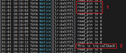
Sample application
The content marked number 1 shows PA7 is connected to PA6. The content marked number 2 shows PA8 changing from floating to GND triggers the external interrupt.
Check out the complete code on GitHub.
LED
tuya_create_led_handle()
OPERATE_RET tuya_create_led_handle(IN CONST tuya_pin_name_t pinname,IN CONST BOOL_T high,OUT LED_HANDLE *handle);
Create an LED device.
Parameters:
pinname: The number of the LED pin.high:TRUE: The LED pin is initialized to high level.FLASE: The LED pin is initialized to low level.
handle: an output parameter, indicating the handle to the LED.
Return:
OPRT_OK: SuccessOthers: Failure
tuya_set_led_light_type()
VOID tuya_set_led_light_type(IN CONST LED_HANDLE handle,IN CONST LED_LT_E type,
                             IN CONST USHORT_T flh_mstime,IN CONST USHORT_T flh_ms_sumtime);
Set the type of LED output.
Parameters:
handle: The handle to the LED.type: The type of LED output, which should be a value of theLED_LT_Eenum.flh_mstime: The interval between LED state changes, in milliseconds.flh_ms_sumtime: The total blink time, in milliseconds. If you set this parameter to0xFFFF, the LED always blinks. The type of this parameter is unsigned short, with a maximum value of 65,534 milliseconds.
Return:
OPRT_OK: SuccessOthers: Failure
The following code snippet lists the LED_LT_E enum values:
typedef enum {
    OL_LOW = 0,    // output level low
    OL_HIGH,       // output level high
    OL_FLASH_LOW,
    OL_FLASH_HIGH,
}LED_LT_E;
OL_FLASH_LOW represents LED blinking, with the final output of the pin set to high level.
OL_FLASH_HIGH represents LED blinking, with the final output of the pin set to low level.
When you set the type to OL_FLASH_LOW or OL_FLASH_HIGH, the LED pin is set to low. Then, the LED blinks as per the configured interval flh_mstime. When the total blink time flh_ms_sumtime is reached, the LED pin is set to the final output state.
Sample application
Check out the complete code on GitHub.
KEY
The following table lists the key functions:
| Function name | Description |
|---|---|
| OPERATE_RET key_init(IN CONST KEY_USER_DEF_S *p_tbl, IN CONST INT_T cnt, IN CONST INT_T timer_space); | Initialize the key service. |
| OPERATE_RET reg_proc_key(IN CONST KEY_USER_DEF_S *key_ud); | Register a new key. |
tuya_key.h is located in sdk\include.
key_init()
OPERATE_RET key_init(IN CONST KEY_USER_DEF_S *p_tbl, IN CONST INT_T cnt, IN CONST INT_T timer_space);
Initialize the key service.
Parameters:
p_tbl: The key configuration struct.cnt: The number of keys to be registered.timer_space: The key press detection time, with no more than 100 milliseconds. If it is set to 0, the default time of 20 milliseconds is used.
Return:
OPRT_OK: SuccessOthers: Failure
The following code snippet lists the key registration struct:
typedef struct {
    /** PIN ID */
    tuya_pin_name_t port;
    /** whether low level trigger */
    BOOL_T low_level_detect;
    /** long press type, see KEY_LONG_PRESS_TP_E */
    KEY_LONG_PRESS_TP_E lp_tp;
    /** unit: ms, lp_tp == LP_ONCE_TRIG then valid and must >= 1000ms */
    USHORT_T long_key_time;
    /** unit:ms , 0:disable default:400ms */
    USHORT_T seq_key_detect_time;
    /** handler of KEY event */
    KEY_CALLBACK call_back;
}KEY_USER_DEF_S;
| Members | Description |
|---|---|
| port | The ID of the key pin. |
| low_level_detect |
|
| lp_tp | For more information about the press-and-hold triggers, see KEY_LONG_PRESS_TP_E enum. |
| long_key_time | The press-and-hold time, in milliseconds. This parameter is valid when lp_tp is LP_ONCE_TRIG. The specified time must be greater than or equal to 1,000 milliseconds. |
| seq_key_detect_time | The detection time for continuous key press, in milliseconds. 0 means to disable detecting continuous key press. The detection time defaults to 400 milliseconds. |
| call_back | The callbacks invoked when a key is pressed. |
The following code snippet lists the KEY_LONG_PRESS_TP_E enum:
typedef enum {
    /** long press invalid */
    LP_INVALID = 0,
    /** long press once trigger */
    LP_ONCE_TRIG,
    /** long press more normal trigger */
    LP_MORE_NORMAL_TRIG,
    /** press key immedialtely trigger */
    FALLING_EDGE_TRIG,
    /** press key immedialtely trigger & LONG */
    FALLING_LONG_TRIG,
}KEY_LONG_PRESS_TP_E;
The function prototype for key press callbacks:
typedef VOID(* KEY_CALLBACK)(tuya_pin_name_t port,PUSH_KEY_TYPE_E type,INT_T cnt);
PUSH_KEY_TYPE_E is the struct of types of key press.
typedef enum {
    /** one shot */
    NORMAL_KEY = 0,
    /** continual shot */
    SEQ_KEY,
    /** long press */
    LONG_KEY,
}PUSH_KEY_TYPE_E;
reg_proc_key()
OPERATE_RET reg_proc_key(IN CONST KEY_USER_DEF_S *key_ud);
Register a new key.
Parameters:
key_ud: The key configuration struct.
Return:
OPRT_OK: SuccessOthers: Failure
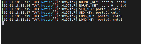
Sample application
The example uses the TUYA_PA9 as the key pin. The log shows the type of key press.
Check out the complete code on GitHub.
UART
The following table lists the UART functions:
| Function name | Description |
|---|---|
| int tuya_uart_init(tuya_uart_t *uart); | Initialize the serial port. |
| int tuya_uart_read(tuya_uart_t *uart, void *data, uint16_t len); | Send serial data. |
| int tuya_uart_write(tuya_uart_t *uart, void *data, uint16_t len); | Read serial data. |
| int tuya_uart_control(tuya_uart_t *uart, uint8_t cmd, void *arg); | Control the serial port. |
| int tuya_uart_deinit(tuya_uart_t *uart); | Deinitialize the serial port. |
tuya_uart.h is located in sdk\include.
For the CBU module (BK7231N built in), UART1 (marked TX2 and RX2) is used to print logs. We recommend you use UART0 (marked TX1 and RX1) to test log print.
tuya_uart_init()
int tuya_uart_init(tuya_uart_t *uart);
Initialize the serial port and request memory allocation.
Parameters:
uart: The serial struct, including the initialization parameters.
Return:
OPRT_OK: SuccessOthers: Failure
int tuya_uart_init(tuya_uart_t *uart); is used to configure the parameters such as baud, data bit, and stop bit.
The following code snippet shows the function prototype for tuya_uart_t:
struct tuya_uart{
    tuya_drv_node_t     node;	// Serial node.
    tuya_uart_cfg_t     cfg;	// Serial configuration parameters.
    tuya_uart_cb_t      cb;		// Serial callbacks.
    tuya_uart_ops_t    *ops;
    void               *rxfifo;
};
typedef struct tuya_uart tuya_uart_t;
tuya_uart_cfg_t in tuya_uart_t is used to configure the serial port.
typedef struct {
    uint16_t                flag;		// Configure the receive or transmit mode.
    uint16_t                bufsz;		// The serial buffer size.
    tuya_uart_baudrate_t    baudrate;	// Baud.
    tuya_uart_databits_t    databits;	// Data bit.
    tuya_uart_stopbits_t    stopbits;	// Stop bit.
    tuya_uart_parity_t      parity;		// Parity.
} tuya_uart_cfg_t;
flag in tuya_uart_cfg_t is used to configure the serial receive or transmit mode. tuya_drv_flag_t is located in sdk\include\tuya_driver.h. The following code snippet shows the available modes.
typedef enum{
    TUYA_DRV_INT_RX_FLAG     = 0x01, // Interrupt reception
    TUYA_DRV_INT_TX_FLAG     = 0x02, // Interrupt transmission
    TUYA_DRV_DMA_RX_FLAG     = 0x04, // DMA reception
    TUYA_DRV_DMA_TX_FLAG     = 0x08, // DMA transmission
    TUYA_DRV_NONBLOCK_FLAG   = 0x10, // Non-blocking
}tuya_drv_flag_t;
The following code snippet shows the available parameters for other configurable options.
// Baud
typedef enum{
    TUYA_UART_BAUDRATE_300        = 300,
    TUYA_UART_BAUDRATE_600        = 600,
    TUYA_UART_BAUDRATE_1200       = 1200,
    TUYA_UART_BAUDRATE_2400       = 2400,
    TUYA_UART_BAUDRATE_4800       = 4800,
    TUYA_UART_BAUDRATE_9600       = 9600,
    TUYA_UART_BAUDRATE_19200      = 19200,
    TUYA_UART_BAUDRATE_38400      = 38400,
    TUYA_UART_BAUDRATE_57600      = 57600,
    TUYA_UART_BAUDRATE_74880      = 74880,
    TUYA_UART_BAUDRATE_115200     = 115200,
    TUYA_UART_BAUDRATE_230400     = 230400,
    TUYA_UART_BAUDRATE_460800     = 460800,
    TUYA_UART_BAUDRATE_921600     = 921600,
    TUYA_UART_BAUDRATE_1500000    = 1500000,
    TUYA_UART_BAUDRATE_1843200    = 1843200,
    TUYA_UART_BAUDRATE_3686400    = 3686400,
}tuya_uart_baudrate_t;

// Data bit
typedef enum{
    TUYA_UART_DATA_BIT5           = 0x05,
    TUYA_UART_DATA_BIT6           = 0x06,
    TUYA_UART_DATA_BIT7           = 0x07,
    TUYA_UART_DATA_BIT8           = 0x08,
}tuya_uart_databits_t;

// Stop bit
typedef enum{
    TUYA_UART_STOP_BIT1           = 0x01,
    TUYA_UART_STOP_BIT1_5         = 0x02,
    TUYA_UART_STOP_BIT2           = 0x03,
}tuya_uart_stopbits_t;

// Parity
typedef enum{
    TUYA_UART_PARITY_NONE         = 0,
    TUYA_UART_PARITY_ODD          = 1,
    TUYA_UART_PARITY_EVEN         = 2,
}tuya_uart_parity_t;
Before you call tuya_uart_init(tuya_uart_t *uart); for serial initialization, call tuya_driver_find() to find the serial device.
The following code snippet uses UART0 to demonstrate the serial initialization:
#include "uni_log.h"
#include "tuya_driver.h"
#include "tuya_uart.h"
...
tuya_uart_t * uart0;

void uart0_init(void)
{
    int32_t op_ret;

    uart0 = (tuya_uart_t *)tuya_driver_find(TUYA_DRV_UART, TY_UART0);
    if (NULL == uart0) {
        PR_DEBUG("find uart0 fail");
        return;
    }

    TUYA_UART_8N1_CFG(uart0, TUYA_UART_BAUDRATE_115200, 256, TUYA_DRV_INT_RX_FLAG);

    op_ret = tuya_uart_init(uart0);
    if (OPRT_OK != op_ret) {
        PR_ERR("uart init fail, error code: %d", op_ret);
    }

    return;
}
...
The example is configured as blocking. To configure the serial port as non-blocking, set the flag in tuya_uart_cfg_t to TUYA_DRV_NONBLOCK_FLAG.
tuya_uart_write()
int tuya_uart_write(tuya_uart_t *uart, void *data, uint16_t len);
Send serial data.
Parameters:
-
uart: The handle to UART. -
data: The pointer to the data to be sent. -
len: The length of the data to be sent.
Return:
The length of data sent.
tuya_uart_read()
int tuya_uart_read(tuya_uart_t *uart, void *data, uint16_t len);
Receive serial data.
Parameters:
uart: The handle to UART.data: an output parameter, the pointer to the address of the received data.len: The maximum length of the data to be received.
Return:
The length of data received.
tuya_uart_control()
int tuya_uart_control(tuya_uart_t *uart, uint8_t cmd, void *arg);
Control the serial device.
Parameters:
uart: The handle to UART.cmd: The command. Possible value:TUYA_DRV_CONFIG_CMD.arg: The parameter to be controlled.
Return:
OPRT_OK: SuccessOthers: Failure
tuya_uart_deinit()
int tuya_uart_deinit(tuya_uart_t *uart);
Deinitialize the serial device. Turn off the serial device and release the occupied serial port.
Parameters:
uart: The serial struct, including the initialization parameters.
Return:
OPRT_OK: SuccessOthers: Failure
Sample application
In the example, UART0 is initialized to 115200 baud. After initialization, hello uart0, baudrate 115200 is printed. Then, UART0 will respond to the data it receives. The serial port is configured as blocking mode by default. You can set UART_NONBLOCK_EN to 1 to initialize the port as non-blocking mode.
Check out the complete code on GitHub.

PWM
The following table shows the mapping between the PWM number and the pin.
| PWM pin number | Pin |
|---|---|
| PWM0 | P6 |
| PWM1 | P7 |
| PWM2 | P8 |
| PWM3 | P9 |
| PWM4 | P24 |
| PWM5 | P26 |
The following table lists the PWM functions:
| Function name | Description |
|---|---|
| int tuya_pwm_init(tuya_pwm_t *pwm); | Initialize the PWM. |
| int tuya_pwm_start(tuya_pwm_t *pwm); | Start the PWM. |
| int tuya_pwm_stop(tuya_pwm_t *pwm); | Stop the PWM. |
| int tuya_pwm_set(tuya_pwm_t *pwm, float frequency, float percent); | Set the PWM frequency and duty cycle. |
| int tuya_pwm_frequency_set(tuya_pwm_t *pwm, float frequency); | Set the PWM frequency. |
| int tuya_pwm_duty_set(tuya_pwm_t *pwm, float percent); | Set the PWM duty cycle. |
| int tuya_pwm_polarity_set(tuya_pwm_t *pwm, tuya_pwm_polarity_t polarity); | Set the initial polarity of the PWM. |
| int tuya_pwm_deinit(tuya_pwm_t *pwm); | Deinitialize the PWM. |
tuya_pwm.h is located in sdk\include.
tuya_pwm_init()
int tuya_pwm_init(tuya_pwm_t *pwm);
Initialize the PWM.
Parameters:
pwm: The handle to the PWM.
Return:
-
OPRT_OK: Success -
Others: Failure
cfg in tuya_pwm_t is the PWM configuration struct.
typedef struct{
    uint8_t         pin;			// PWM pin number
    uint8_t         polarity;		// PWM polarity
    uint32_t        period_ns;		// PWM output period
    uint32_t        pulse_ns;		// PWM output pulse width
    float           percent;		// PWM duty cycle
}tuya_pwm_cfg_t;
pin indicates the PWM pin.
polarity is used to set the polarity of the PWM.
typedef enum{
    TUYA_PWM_POSITIVE = 0,
    TUYA_PWM_NEGATIVE,
}tuya_pwm_polarity_t;
period_ns is the period of the PWM output, which is used to configure the frequency of the PWM output. The relation between the period_ns and the frequency is:
period_ns = (uint32_t)1000000000 ÷ frequency
pulse_ns is the pulse width of the PWM output, which is used to configure the PWM duty cycle. The formula for PWM duty cycle:
pulse_ns = period_ns × percent
In practice, you can operate the related struct or use the macro TUYA_PWM_CFG to configure the PWM. The following code snippet shows the function prototype for TUYA_PWM_CFG:
#define TUYA_PWM_CFG(__PWM, __PIN, __FREQUENCY, __PERCENT)                      \
    (__PWM)->cfg.pin       = __PIN;                                             \
    (__PWM)->cfg.period_ns = (uint32_t)1000000000 / (__FREQUENCY);              \
    (__PWM)->cfg.percent   = __PERCENT;                                       \
    (__PWM)->cfg.pulse_ns  = (uint32_t)((__PWM)->cfg.period_ns * (__PERCENT));  \
    (__PWM)->cfg.polarity  = TUYA_PWM_POSITIVE
tuya_pwm_start()
int tuya_pwm_start(tuya_pwm_t *pwm);
Start the PWM.
Parameters:
pwm: The handle to the PWM.
Return:
OPRT_OK: SuccessOthers: Failure
tuya_pwm_stop()
int tuya_pwm_stop(tuya_pwm_t *pwm);
Stop the PWM.
Parameters:
pwm: The handle to the PWM.
Return:
-
OPRT_OK: Success -
Others: Failure
tuya_pwm_set()
int tuya_pwm_set(tuya_pwm_t *pwm, float frequency, float percent);
Set the PWM frequency and duty cycle.
Parameters:
pwm: The handle to the PWM.frequency: PWM frequency.percent: PWM duty cycle, ranging from 0 to 1.0.
Return:
-
OPRT_OK: Success -
Others: Failure
tuya_pwm_frequency_set()
int tuya_pwm_frequency_set(tuya_pwm_t *pwm, float frequency);
Set the PWM frequency.
Parameters:
pwm: The handle to the PWM.frequency: PWM frequency.
Return:
-
OPRT_OK: Success -
Others: Failure
tuya_pwm_duty_set()
int tuya_pwm_duty_set(tuya_pwm_t *pwm, float percent);
Set the PWM duty cycle.
Parameters:
pwm: The handle to the PWM.percent: PWM duty cycle, ranging from 0 to 1.0.
Return:
-
OPRT_OK: Success -
Others: Failure
tuya_pwm_polarity_set()
int tuya_pwm_polarity_set(tuya_pwm_t *pwm, tuya_pwm_polarity_t polarity);
Set the polarity of the PWM.
Parameters:
pwm: The handle to the PWM.polarity: The polarity of the PWM.
Return:
-
OPRT_OK: Success -
Others: Failure
The following code snippet shows the function prototype for tuya_pwm_polarity_t:
typedef enum {
    TUYA_PWM_POSITIVE = 0,
    TUYA_PWM_NEGATIVE,
} tuya_pwm_polarity_t;
tuya_pwm_deinit()
int tuya_pwm_deinit(tuya_pwm_t *pwm);
Deinitialize the PWM.
Parameters:
pwm: The handle to the PWM.
Return:
-
OPRT_OK: Success -
Others: Failure
Sample application
The example shows how to initialize the PWM. You can call the above API to set the PWM.
Check out the complete code on GitHub.
ADC
The ADC on the CBU module has an input range of 0 to 2.4V.
The following table shows the mapping between the ADC number and the pin.
| SDK enum | Silkscreen markings |
|---|---|
| TUYA_ADC0 | P26 |
| TUYA_ADC1 | P24 |
| TUYA_ADC2 | ADC(P23) |
The following table lists the ADC functions:
| Function name | Description |
|---|---|
| int tuya_adc_init(tuya_adc_t *adc); | Initialize the ADC. |
| int tuya_adc_convert(tuya_adc_t *adc, uint16_t *data, uint16_t num); | Convert analog signals to digital signals. |
| int tuya_adc_deinit(tuya_adc_t *adc); | Deinitialize the ADC. |
tuya_adc.h is located in sdk\include.
tuya_adc_init()
int tuya_adc_init(tuya_adc_t *adc);
Initialize the ADC. Initialize the ADC and request memory allocation.
Parameters:
adc: The handle to the ADC.
Return:
-
OPRT_OK: Success -
Others: Failure
tuya_adc_convert()
int tuya_adc_convert(tuya_adc_t *adc, uint16_t *data, uint16_t num);
The ADC converts analog signals to digital signals. You can get the raw data converted by the ADC, with a maximum value of 4096.
Parameters:
adc: The handle to the ADC.data: The raw data converted by the ADC.num: The number of ADC captures.
Return:
-
OPRT_OK: Success -
Others: Failure
tuya_adc_deinit()
int tuya_adc_deinit(tuya_adc_t *adc);
Deinitialize the ADC. Turn off the ADC and release the occupied resource.
Parameters:
adc: The handle to the ADC.
Return:
-
OPRT_OK: Success -
Others: Failure
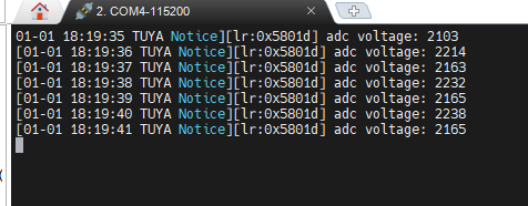
Sample application
The example shows the initialization process of the ADC pin TUYA_ADC2, which is marked ADC(P23). After initialization, the logger prints the captured data after conversion (1,000 times the actual voltage value) every one second.
Check out the complete code on GitHub.
TIMER
The following table lists the timer functions:
| Function name | Description |
|---|---|
| int tuya_timer_init(tuya_timer_t *timer); | Initialize the timer. |
| int tuya_timer_start(tuya_timer_t* timer, uint32_t us); | Start the timer. |
| int tuya_timer_stop(tuya_timer_t* timer); | Stop the timer. |
| int tuya_timer_deinit(tuya_timer_t* timer); | Deinitialize the timer. |
tuya_timer.h is located in sdk\include.
tuya_timer_init()
int tuya_timer_init(tuya_timer_t *timer);
Initialize the timer.
Parameters:
timer: The handle to the timer.
Return:
-
OPRT_OK: Success -
Others: Failure
Before you call tuya_timer_init() for timer initialization, call tuya_driver_find() to find the serial device and then configure the timer.
When you call void *tuya_driver_find(uint8_t type, uint8_t port); to find a timer, port should be passed in. The following code snippet shows the available parameters to the port.
typedef enum {
    TUYA_TIMER0 = 0,
    TUYA_TIMER1,
    TUYA_TIMER2,
    TUYA_TIMER3,
    TUYA_TIMER4,
    TUYA_TIMER5,
} tuya_timer_port_t;
The configurable parameters for a timer:
typedef enum {
    TUYA_TIMER_MODE_ONCE = 0,	// One-time
    TUYA_TIMER_MODE_PERIOD		// Recurring
} tuya_timer_mode_t;

typedef struct {
    tuya_timer_mode_t    mode;	// Mode
    tuya_timer_isr_cb    cb;	// Callback
    void                *arg;	// Parameter
} tuya_timer_cfg_t;
To configure a timer, you can directly edit the struct or use the following macro.
#define TUYA_TIMER_CFG(__TIMER, __MODE, __CB, __ARG)                          \
    (__TIMER)->cfg.mode = __MODE;                                             \
    (__TIMER)->cfg.cb   = __CB;                                               \
    (__TIMER)->cfg.arg  = __ARG
Populate __TIMER with the struct pointer returned by tuya_driver_find().
__MODE is used to specify whether a timer is one-time or recurring, which is selected from the tuya_timer_mode_t enum.
__CB is the callback invoked when the timer expires.
__ARG is the parameter value that passed in to the callback.
After configuration, you can invoke tuya_timer_init() to initialize a timer and then call tuya_timer_start() to start the timer.
tuya_timer_start()
int tuya_timer_start(tuya_timer_t* timer, uint32_t us);
Start the timer.
Parameters:
timer: The handle to the timer.us: The timeout period, in microseconds.
Return:
-
OPRT_OK: Success -
Others: Failure
tuya_timer_stop()
int tuya_timer_stop(tuya_timer_t* timer);
Stop the timer.
Parameters:
timer: The handle to the timer.
Return:
-
OPRT_OK: Success -
Others: Failure
After a timer is stopped, the occupied resource is not released, so you can call tuya_timer_start() to start the timer without initializing it again.
tuya_timer_deinit()
int tuya_timer_deinit(tuya_timer_t* timer);
Deinitialize the timer.
Parameters:
timer: The handle to the timer.
Return:
-
OPRT_OK: Success -
Others: Failure
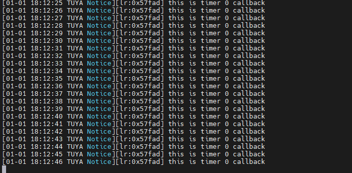
Sample application
The example shows how to initialize a timer to a recurring schedule with a timeout period of one second. The callback is invoked every one second, with a piece of log printed.
Check out the complete code on GitHub.
Is this page helpful?
YesFeedbackIs this page helpful?
YesFeedback


