WRG2-IPEX Module Datasheet
WRG2-IPEX is a Tuya Wi-Fi module featured in gateway Armcore. It consists of a highly integrated RF chip (8197FS) and peripherals. Besides, it has rich peripheral interfaces and the Realtek 2x2 Wi-Fi.
Features
-
Basic features
- Support the 2x2 IEEE 802.11 b/g/n mode
- Support the band width of 40MHz
- Maximum transmit power: 18 dB
- Receive power: -99dB@1M
- Frequency band: 2412 MHz to 2484 MHz
-
Working conditions
- Voltage range: 3.15 to 3.45V. The recommended voltage: 3.3V
- Working temperature: 0 to 75℃
-
Security feature: Support WPA-PSK/WPA2-PSK/WPA/WPA2/AES 128
Applications
The module featured in gateway Armcore is used for finished products, such as gateway.
Module interfaces
Dimensions and footprint
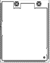
WRG2-IPEX has 74 pins in total. The distance between two pins is 1.4±0.1 mm.
The dimensions of WRG2-IPEX are 42±0.35 mm (L)×33±0.35 mm (W) ×3.4±0.15 mm (H). The thickness of the PCB is 0.8±0.1 mm.
WRG2-IPEX is shown below:
Pin definition
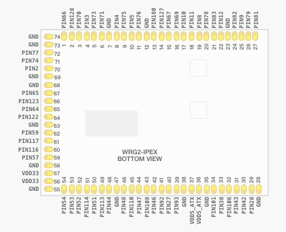
| Pin number | The corresponded pin on the IC | Function |
|---|---|---|
| 1 | Pin 66 | Default IIS_MCLK |
| 2 | Pin128 | Default IIS_SCLK |
| 3 | Pin 70 | Default IIS_WS |
| 4 | Pin 3 | Default IIS_SD |
| 5 | Pin 73 | Default IIC_SDA |
| 6 | Pin 71 | Default IIC_SCL |
| 7 | GND | GND |
| 8 | Pin 4 | Default UART1_CTS |
| 9 | Pin 75 | Default UART1_RX |
| 10 | Pin 5 | Default UART1_TX |
| 11 | Pin 76 | Default UART1_RTS |
| 12 | GND | GND |
| 13 | Pin 80 | If the SD function uses the pin, the output voltage is 1.8V/3.3V. |
| 14 | Pin 127 | Optionally connected to the SD card. Used to enable or disable the power supply to the SD card, or used as a GPIO |
| 15 | Pin 67 | Optionally connected to the SD card. Used to write protection to the SD card, or used as a GPIO. |
| 16 | Pin 69 | Optionally connected to the SD card. Used to detect the SD card, or used as a GPIO. |
| 17 | Pin 10 | Optionally connected to the SD card. Used to output the clock signal of the SD card, or used as a GPIO. |
| 18 | Pin 11 | Optionally connected to the SD card. Used to output a command to the SD card, or used as a GPIO. |
| 19 | Pin 8 | Optionally connected to the SD card. Used for data transmission of the SD card, or used as a UART2_RX. |
| 20 | Pin 78 | Optionally connected to the SD card. Used for data transmission of the SD card, or used as a UART2_CTS. |
| 21 | Pin 83 | Optionally connected to the SD card. Used for data transmission of the SD card, or used as a UART2_RTS. |
| 22 | Pin 12 | Optionally connected to the SD card. Used for data transmission of the SD card, or used as a UART2_TX. |
| 23 | GND | GND |
| 24 | Pin 82 | By default, the pin is a common GPIO. |
| 25 | Pin 9 | By default, the pin is a common GPIO. |
| 26 | Pin 79 | By default, the pin is a common GPIO. |
| 27 | Pin 81 | By default, the pin is a common GPIO. |
| 28 | GND | GND |
| 29 | Pin 28 | By default, the pin is used as a LED light or a common GPIO. |
| 30 | Pin 42 | By default, the pin is used as a LED light or a common GPIO. |
| 31 | Pin 43 | By default, the pin is used as a LED light or a common GPIO. |
| 32 | Pin 106 | By default, the pin is used as a LED light or a common GPIO. |
| 33 | Pin 38 | By default, it is used as UART0_RX for receiving logs. |
| 34 | Pin 101 | By default, it is used as UART0_TX for transmitting logs. |
| 35 | GND | GND |
| 36 | VDD5_ATX | If a PA is added, the external power supply of 5V is needed. If a PA is not needed, do not connect the pin to anything. |
| 37 | VDD5_ATX | If a PA is added, the external power supply of 5V is needed. If a PA is not needed, do not connect the pin to anything. |
| 38 | GND | GND |
| 39 | Pin 93 | By default, if a PA is not added, it can be used as a GPIO. If a PA is added, the pin needs to act as the PA control pin. |
| 40 | Pin 27 | By default, if a PA is not added, it can be used as a GPIO. If a PA is added, the pin needs to act as the PA control pin. |
| 41 | Pin 92 | By default, if a PA is not added, it can be used as a PTA control pin. |
| 42 | Pin 46 | By default, if a PA is not added, it can be used as a PTA control pin. |
| 43 | Pin 108 | By default, if a PA is not added, it can be used as a PTA control pin. |
| 44 | Pin 47 | By default, a PA is not added, it can be used as a GPIO. If a PA is added, the pin needs to act as the PA control pin. |
| 45 | Pin 110 | By default, if a PA is not added, it can be used as a GPIO. If a PA is added, the pin needs to act as the PA control pin. |
| 46 | Pin 48 | By default, it is used as a GPIO. |
| 47 | GND | GND |
| 48 | Pin 44 | By default, it is used as PCIE_RSTN. |
| 49 | Pin 113 | By default, it is used as PCIE_HSOP. |
| 50 | Pin 51 | By default, it is used as PCIE_HSON. |
| 51 | Pin 114 | By default, it is used as PCIE_CLK_P. |
| 52 | Pin 52 | By default, it is used as PCIE_CLK_N. |
| 53 | Pin 53 | By default, it is used as PCIE_HSIP. |
| 54 | Pin 54 | By default, it is used as PCIE_HSIN. |
| 55 | GND | GND |
| 56 | VDD33 | Power supply of 3.3V |
| 57 | VDD33 | Power supply of 3.3V |
| 58 | GND | GND |
| 59 | Pin 57 | By default, it is used as the first group USB—USBDN0. |
| 60 | Pin 116 | By default, it is used as the first group USB—USBDP0. |
| 61 | Pin 117 | By default, it is used as the second group USB—USBDN1. |
| 62 | Pin 59 | By default, it is used as the second group USB—USBDP1. |
| 63 | GND | GND |
| 64 | Pin 122 | By default, it is used as the network interface—TXOP4. |
| 65 | Pin 64 | By default, it is used as the network interface—TXON4 |
| 66 | Pin 123 | By default, it is used as the network interface—RXIP4 |
| 67 | Pin 65 | By default, it is used as the network interface—RXIN4 |
| 68 | GND | GND |
| 69 | GND | GND |
| 70 | Pin 2 | By default, it is used as a common GPIO. |
| 71 | Pin 74 | By default, it is used as a common GPIO. |
| 72 | Pin 77 | By default, it is used as a common GPIO. |
| 73 | GND | GND |
| 74 | GND | GND |
Note:
The above is the default pin definition of Tuya. Currently, there is no PA in the module featured in gateway Armcore. Its purpose is to achieve the PTA function.
If you have any other definitions and requirements on pins, please contact Tuya business personnel.
Electrical parameters
Absolute electrical parameters
| Parameter | Minimum value | Maximum value | Unit |
|---|---|---|---|
| Ts | -55 | 125 | ℃ |
| Working temperature | 0 | 70 | ℃ |
| Junction temperature | 0 | 125 | ℃ |
Normal working conditions
| Parameter | Description | Minimum value | Typical value | Maximum value | Unit |
|---|---|---|---|---|---|
| Ta | Working temperature | 0 | - | 70 | ℃ |
| VCC | Working voltage | 3.15 | 3.3 | 3.45 | V |
Power consumption during consistent transmission and reception and in power-consumption state
| Symbol | Conditions | Average value | Maximum value (Typical value) | Unit |
|---|---|---|---|---|
| Itx | Constantly transmit, output power of 18dB in 11b 1M | 500 | 560 | mA |
| Itx | Constantly transmit, output power of 14.5dB in 11g 54M | 460 | 580 | mA |
| Itx | Constantly transmit, output power of 14dB in 11n HT20 MCS7 | 460 | 540 | mA |
| Itx | Constantly transmit, output power of 14dB in 11n HT40 MCS7 | 450 | 540 | mA |
| Irx | Constantly receive in 11b 11M | 360 | 407 | mA |
| Irx | Constantly receive in 11g 54M | 360 | 407 | mA |
| Irx | Constantly receive in 11n HT20 MCS7 | 360 | 407 | mA |
| Irx | Constantly receive in 11n HT40 MCS7 | 360 | 407 | mA |
RF parameters
Basic RF features
| Parameter | Description |
|---|---|
| Working frequency | Wi-Fi: 2.412 GHz to 2.484 Ghz (Ch1-11 for US/CA,Ch1-13 for EU/CN); |
| Wi-Fi standard | IEEE 802.11b/g/n |
| Data transmission rate | Wi-Fi: 11b:1, 2, 5.5, 11 (Mbps) 11g: 6, 9, 12, 18, 24, 36, 48, 54(Mbps) 11n: HT20 MCS 0 to 7 11n: HT40 MCS 0 to 7 |
| Antenna Type | IPEX antenna |
TX performance
TX performance
| Parameter | Minimum value | Typical value | Maximum value | Unit |
|---|---|---|---|---|
| Average RF output power, 802.11b CCK Mode 11M | - | 18 | - | dBm |
| Average RF output power, 802.11g OFDM Mode 54M | - | 14.5 | - | dBm |
| Average RF output power, 802.11n HT20 Mode MCS7 | - | 14 | - | dBm |
| Average RF output power, 802.11n HT40 Mode MCS7 | - | 14 | - | dBm |
RX performance
RX sensitivity
| Parameter | Minimum value | Typical value | Maximum value | Unit |
|---|---|---|---|---|
| PER<8%, RX sensitivity, 802.11b DSSS Mode 1M | - | -99 | - | dBm |
| PER<10%, RX sensitivity, 802.11g 54 M | - | -76 | - | dBm |
| PER<10%, RX sensitivity, 802.11n HT20-MCS7 | - | -72.5 | - | dBm |
| PER<10%, RX sensitivity, 802.11n HT40-MCS7 | - | -69.5 | - | dBm |
Packaging information and production instructions
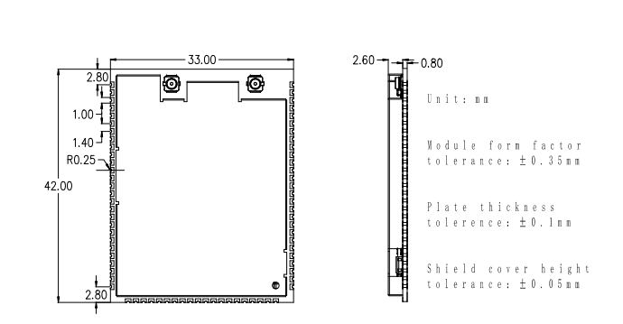
Mechanical dimensions
The dimensions of the PCB are 42±0.35 mm (L)×33±0.35 mm (W) ×0.8±0.1 mm (H)
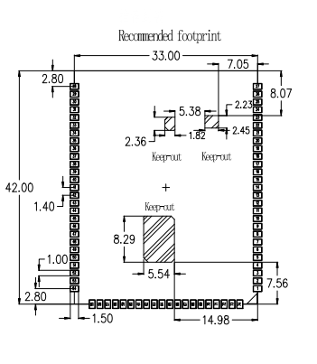
Recommended PCB footprint
Production instructions
- The Tuya SMT module should be mounted by the SMT device. After being unpacked, it should be soldered within 24 hours. Otherwise, it should be put into the drying cupboard where the RH is not greater than 10%; or it needs to be packaged under vacuum again and the exposure time needs to be recorded (the total exposure time cannot exceed 168 hours).
- SMT devices:
- Mounter
- SPI
- Reflow soldering machine
- Thermal profiler
- Automated optical inspection (AOI) equipment
- Baking devices:
- Cabinet oven
- Anti-electrostatic and heat-resistant trays
- Anti-electrostatic and heat-resistant gloves
- SMT devices:
- Storage conditions for a delivered module:
-
The moisture-proof bag must be placed in an environment where the temperature is below 40°C and the relative humidity is lower than 90%.
-
The shelf life of a dry-packaged product is 12 months from the date when the product is packaged and sealed.
-
There is a humidity indicator card (HIC) in the packaging bag.

-
- The module needs to be baked in the following cases:
- The packaging bag is damaged before unpacking.
- There is no HIC in the packaging bag.
- After unpacking, circles of 10% and above on the HIC become pink.
- The total exposure time has lasted for over 168 hours since unpacking.
- More than 12 months have passed since the sealing of the bag.
- Baking settings:
- Temperature: 40°C and ≤ 5% RH for reel package and 125°C and ≤5% RH for tray package (please use the heat-resistant tray rather than a plastic container)
- Time: 168 hours for reel package and 12 hours for tray package
- Alarm temperature: 50°C for reel package and 135°C for tray package
- Production-ready temperature after natural cooling: < 36°C
- Re-baking situation: If a module remains unused for over 168 hours after being baked, it needs to be baked again.
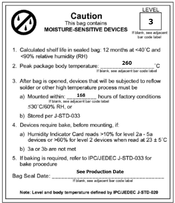
- If a batch of modules is not baked within 168 hours, do not use the wave soldering to solder them. Because these modules are Level-3 moisture-sensitive devices, they are very likely to get damp when exposed beyond the allowable time. In this case, if they are soldered at high temperatures, it may result in device failure or poor soldering.
- In the whole production process, take electrostatic discharge (ESD) protective measures.
- To guarantee the passing rate, it is recommended that you use the SPI and AOI to monitor the quality of solder paste printing and mounting.
Recommended oven temperature curve
Set oven temperatures according to the following temperature curve of reflow soldering. The peak temperature is 245°C.

-
A: Temperature axis
-
B: Time axis
-
C: Liquidus temperature: 217 to 220°C
-
D: Ramp-up slope: 1 to 3°C/s
-
E: Duration of constant temperature: 60 to 120s; the range of constant temperature: 150 to 200°C
-
F: Duration above the liquidus: 50 to 70s
-
G: Peak temperature: 235 to 245°C
-
H: Ramp-down slope: 1 to 4°C/s
Note: The above curve is just an example of the solder paste SAC305. For more details about other solder pastes, please refer to Recommended oven temperature curve in the solder paste specifications.
Storage conditions
MOQ and packaging information
| Product number | MOQ (pcs) | Shipping packaging method | The number of modules per reel | The number of reels per carton |
|---|---|---|---|---|
| WRG2-IPEX | 1480 | Tape reel | 370 | 4 |
Is this page helpful?
YesFeedbackIs this page helpful?
YesFeedback


