Access Control Protocol
This topic describes the serial port protocol in the Tuya Wi-Fi connection solutions, applicable for door lock and access control products.
Serial communication convention
- Baud: 9600, 115200, and 230400
Note: To ensure picture transfer speed, the minimum baud rate of the module with the picture transfer function must be configured as 115200.
- Data bit: 8
- Parity check: none
- Stop bit: 1
- Data flow control: none
- MCU: Micro Controller Unit. The MCU is connected to Tuya modules through serial ports. Regarding the protocol design, the interaction of all packets is designed as full-duplex communication.
Frame format
| Field | Length (byte) | Description |
|---|---|---|
| Header | 2 | It is fixed as 0x55aa |
| Version | 1 | It is used for update and extension |
| Command | 1 | Specific command |
| Data length | 2 | The length of the data after the data length and before the checksum |
| Data | N | — |
| Checksum | 1 | Start from the header, add up all the bytes, and then divide the sum by 256 to get the remainder |
Note:
- All data must be transmitted in the big-endian mode.
- All sample data in the protocol are in hexadecimal.
- The packets sent by the Wi-Fi module time out after 500 ms. One packet will be resent twice.
-
Generally, one command is sent by one party and received by the other party in a synchronous way. That is, one party sends the command, and the other party responds. If the sender does not receive the correct response packet within the specified time, the transmission times out, as shown in the following figure.
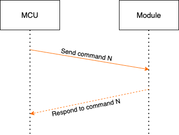
Note: For specific communication modes, see the section Protocol details.
-
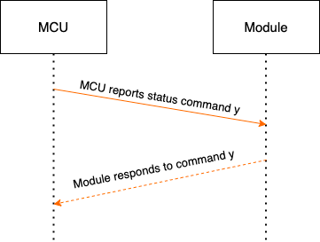
The MCU reports status in a synchronous way. For example, if the MCU reports command y, its communication with the module is shown in the following figure.
The MCU reports statistical data:
Protocol list
Query product information
Product information consists of the product ID (PID) and MCU software version number.
- Product ID: the product ID (PID) on the Tuya Developer Platform. It is generated by the Tuya Developer Platform to record product information in the cloud.
- MCU software version format: Use dot-decimal notation, "x.x.x" (0 ≤ x ≤ 99), and "x" is a decimal digit.
| Field | Length (byte) | Description |
|---|---|---|
| Header | 2 | 0x55aa |
| Version | 1 | 0x00 |
| Command | 1 | 0x01 |
| Data length | 2 | 0x0000 |
| Data | 0 | None |
| Checksum | 1 | Start from the header, add up all the bytes, and then divide the sum by 256 to get the remainder |
The module sends the following command:
55 aa 00 01 00 00 00
The MCU returns the following command:
| Field | Length (byte) | Description |
|---|---|---|
| Header | 2 | 0x55aa |
| Version | 1 | 0x00 |
| Command | 1 | 0x01 |
| Data length | 2 | N |
| Data | N | {"p":"vHXEcqntLpkAlOsy", "v":"1.0.0", "n":0, "cap":0} |
| Checksum | 1 | Start from the header, add up all the bytes, and then divide the sum by 256 to get the remainder |
For example, {"p":"vHXEcqntLpkAlOsy","v":"1.0.0","n":0,"cap":0}
-
The
nfield (optional) represents the network pairing mode. If this field is not uploaded, you can switch between two network pairing modes. The available pairing mode depends on the module.-
Pairing through Wi-Fi Easy Connect and access point (AP) mode
The module supports AP pairing and Wi-Fi Easy Connect automatically.
-
Only AP pairing mode
In this mode, the product can only be paired through AP connection.
-
-
The
capfield indicates device capabilities:bit0: indicates whether the device supports the picture upload function. 0: not support, 1: support.bit1: indicates which communication method the device uses to upload pictures. 0: serial port, 1: serial peripheral interface (SPI).bit2: indicates whether the device is a carrier device. 0: not support, 1: support. This function is unavailable currently.bit3: indicates whether the device supports notification of module reset. 0: not support, 1: support.- The other bits are currently 0 by default. Manage the status for the MCU, and fill 0 in the reserved bits.
The MCU returns the following command:
55 aa 00 01 00 24 7b 22 70 22 3a 22 76 48 58 45 63 71 6e 74 4c 70 6b 41 6c 4f 73 79 22 2c 22 76 22 3a 22 31 2e 30 2e 30 22 7d bf
Report device network status
When the Wi-Fi status of the module changes, Wi-Fi status is sent to the MCU.
| Status | Description | Status value |
|---|---|---|
| Status 1 | Pairing through Wi-Fi Easy Connect | 0x00 |
| Status 2 | Pairing through AP | 0x01 |
| Status 3 | Wi-Fi has been configured, but not connected to the router | 0x02 |
| Status 4 | Wi-Fi has been configured, and connected to the router | 0x03 |
| Status 5 | Wi-Fi has been connected to the router and the cloud | 0x04 |
| Status 6 | The Wi-Fi device is in the low power mode | 0x05 |
| Wi-Fi Easy Connect and AP mode coexist | 0x06 (unavailable currently) |
Note:
- For status 1 and status 2, the MCU shall display the pairing status.
- In principle, you need to configure two pairing methods for the device. For the first pairing method, a few routers have compatibility issues. The second pairing method ensures that the device can be connected to the network.
- Before pairing, the power-on module runs in low power mode by default. After the MCU sends a command to reset the Wi-Fi, the module will enter the pairing status.
- After the device is removed from a mobile phone, the module enters low power mode. After the MCU sends a command to reset the Wi-Fi, the module will enter the status of waiting for pairing.
- After the Wi-Fi module enters pairing mode, if the module fails to connect to the router within 10 seconds and the module is power-off, the module will still be in the previous pairing status after it is powered on next time.
The module sends the following command:
| Field | Length (byte) | Description |
|---|---|---|
| Header | 2 | 0x55aa |
| Version | 1 | 0x00 |
| Command | 1 | 0x02 |
| Data length | 2 | 0x0001 |
| Data | 1 | Indicate Wi-Fi working status, as shown in Network status table |
| Checksum | 1 | Start from the header, add up all the bytes, and then divide the sum by 256 to get the remainder |
The module sends the following command:
55 aa 00 02 00 01 04 06 (the device is connected to the router and the cloud)
The MCU returns the following command:
| Field | Length (byte) | Description |
|---|---|---|
| Header | 2 | 0x55aa |
| Version | 1 | 0x00 |
| Command | 1 | 0x02 |
| Data length | 2 | 0x0000 |
| Data | 0 | None |
| Checksum | 1 | Start from the header, add up all the bytes, and then divide the sum by 256 to get the remainder |
The MCU returns the following command:
55 aa 00 02 00 00 01
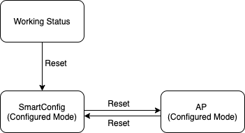
Reset the Wi-Fi
Status change of resetting the Wi-Fi is shown as follows:
The MCU sends the following command:
| Field | Length (byte) | Description |
|---|---|---|
| Header | 2 | 0x55aa |
| Version | 1 | 0x00 |
| Command | 1 | 0x03 |
| Data length | 2 | 0x0000 |
| Data | 0 | None |
| Checksum | 1 | Start from the header, add up all the bytes, and then divide the sum by 256 to get the remainder |
The MCU sends the following command:
55 aa 00 03 00 00 02
The module returns the following command:
| Field | Length (byte) | Description |
|---|---|---|
| Header | 2 | 0x55aa |
| Version | 1 | 0x00 |
| Command | 1 | 0x03 |
| Data length | 2 | 0x0000 |
| Data | 0 | None |
| Checksum | 1 | Start from the header, add up all the bytes, and then divide the sum by 256 to get the remainder |
The module returns the following command:
55 aa 00 03 00 00 02
Reset the Wi-Fi and select the pairing mode
- Compared to Reset the Wi-Fi, with this frame, the MCU can select the required pairing mode after the Wi-Fi is reset.
- You can implement this protocol selectively.
The MCU sends the following command:
| Field | Length (byte) | Description |
|---|---|---|
| Header | 2 | 0x55aa |
| Version | 1 | 0x00 |
| Command | 1 | 0x04 |
| Data length | 2 | 0x0001 |
| Data | 1 |
|
| Checksum | 1 | Start from the header, add up all the bytes, and then divide the sum by 256 to get the remainder |
The MCU sends the command to let the module enter AP pairing mode:
55 aa 00 04 00 01 01 05
The module returns the following command:
| Field | Length (byte) | Description |
|---|---|---|
| Header | 2 | 0x55aa |
| Version | 1 | 0x00 |
| Command | 1 | 0x04 |
| Data length | 2 | 0x0000 |
| Data | 0 | None |
| Checksum | 1 | Start from the header, add up all the bytes, and then divide the sum by 256 to get the remainder |
The module returns the following command:
55 aa 00 04 00 00 03
Report the real-time status
If a device has an alert function and requires real-time notification, you can use this protocol to update the status data. Therefore, the MCU can send real-time status data.
- Status data is directly sent to the cloud, so the device shall be connected to the cloud already. Otherwise, the device fails to report the data.
- This command is a synchronous command. The MCU reports the data and then waits for the result returned by the module. The waiting timeout is five seconds.
- Support the reporting of multiple data units and single data unit. You can select the packet sending mode as needed. For more information about the data packet, see the following example.
The MCU sends the following command:
| Field | Length (byte) | Description |
|---|---|---|
| Header | 2 | 0x55aa |
| Version | 1 | 0x00 |
| Command | 1 | 0x05 |
| Data length | 2 | It depends on types and the number of status data units |
| Data | N | One or multiple status data unit groups |
| Checksum | 1 | Start from the header, add up all the bytes, and then divide the sum by 256 to get the remainder |
The module returns the following command:
| Field | Length (byte) | Description |
|---|---|---|
| Header | 2 | 0x55aa |
| Version | 1 | 0x00 |
| Command | 1 | 0x05 |
| Data length | 2 | 0x0001 |
| Data | 1 | 0x00: success, 0x01: failure |
| Checksum | 1 | Start from the header, add up all the bytes, and then divide the sum by 256 to get the remainder |
An example of reporting a single status data unit:
55 aa 00 05 00 05 6d 01 00 01 01 79 (DP 109, Boolean variable, the value is 1)
An example of reporting multiple status data units:
55 aa 00 05 00 15 6d 01 00 01 01 66 03 00 0c 32 30 31 38 30 34 31 32 31 35 30 37 5d (DP 109, Boolean variable, the value is 1. DP 102, string variable, the value is 201804121507. The specific transmission corresponds to ASCII.)
Report record type data
Scenario:
A door lock contains multiple data point (DP) data, which shall be processed by the server as one record. In case of transient network failure, the data that cannot be reported will be saved through this command. This command can report the status of record type devices. The report shall indicate the local time.
Description:
When the MCU requires the whole data that combines multiple DPs and that shall be reported as a whole, this command can be used to send the data to the Wi-Fi module.
If the device is disconnected from the network when the data is being reported, the module will save the data. During the next data transmission, the module will upload the data, and report it together with previously saved data.
-
Each time when a pending record is reported successfully, the module will return
0x08command with data0x01. -
The maximum length of the data area reported in one record (multiple status data units) is 80. The finally combined and actually saved data length might change, depending on the actual DP data. When no network is available, in case of exceeding the specified length, the Wi-Fi module will return the result that the record cannot be sent.
-
Maximum 400 historical records can be saved by the module. In case of exceeding the limit, the earliest records will be overwritten.
-
The push is successful (
0x00) when the Wi-Fi module receives a packet that a piece of data is successfully pushed, or if the network is unavailable, the record is stored in the flash memory. When the network is connected, each time the module successfully pushes one of the pending records, it will return0x01. In other cases, it will return0x02to represent the push failure. -
The time data in the protocol is to guarantee that the recorded data is consistent with the actual events when the device is disconnected. If the time data is generated when the data arrives at the server, the recorded data generated when the device is temporarily disconnected will be inconsistent with the actual event when the network is restored next time. Therefore, when the Wi-Fi module is paired, if the network is connected, the current time data can be got through the protocol. Each time when a record with the current time data is transmitted, the server recognizes the time that is given by the device.
-
Due to time zone and daylight saving time (DST) in different regions, the device time is also treated accordingly. If the device does not display local time, it can get the Greenwich Mean Time (GMT) according to the protocol. When time-related data is reported, the current GMT of the device is entered according to the protocol. If the device displays local time, it can get the local time from the module through the protocol. Local time is calculated by applying an offset based on the time zone and DST. When time-related data is generated, the local time of the device is entered according to the protocol.
The MCU sends the following command:
| Field | Length (byte) | Description |
|---|---|---|
| Header | 2 | 0x55aa |
| Version | 1 | 0x00 |
| Command | 1 | 0x08 |
| Data length | 2 | It depends on types and the number of status data units. |
| Data | 7 | The data length is 7 bytes.
|
| — | N | One or multiple groups. See status data unit groups. |
| Checksum | 1 | Start from the header, add up all the bytes, and then divide the sum by 256 to get the remainder |
The module returns the following command:
| Field | Length (byte) | Description |
|---|---|---|
| Header | 2 | 0x55aa |
| Version | 1 | 0x00 |
| Command | 1 | 0x08 |
| Data length | 2 | 0x0001 |
| Data | 1 |
|
| Checksum | 1 | Start from the header, add up all the bytes, and then divide the sum by 256 to get the remainder |
An example of data packet transmission is shown as follows.
An example of reporting a single status data unit:
The DP 109 is a Boolean variable, and the value is 1.
-
The time complies with the server time:
55 aa 00 08 00 0c 00 12 04 13 0d 04 14
6d 01 00 01 01d1 -
If the time complies with the local time of the device, for example, April 19, 2018 at 13:03:29 (GMT+08:00):
55 aa 00 08 00 0c 01 12 04 13 0d 03 1d
6d 01 00 01 01da -
If the time complies with the GMT, for example, April 19, 2018 at 05:03:29.
55 aa 00 08 00 0c 02 12 04 13 05 03 1d
6d 01 00 01 01d3
An example of reporting multiple status data units:
The DP 109 is a Boolean variable, and the value is 1.
The DP 102 is a string variable, and the value is an ASCII code of 201804121507.
-
The time complies with the server time
55 aa 00 08 00 1c 00 12 04 13 0d 06 04
6d 01 00 01 0166 03 00 0c 32 30 31 38 30 34 31 32 31 35 30 37a7 -
If the time complies with the local time of the device, for example, April 19, 2018 at 13:03:29 (GMT+08:00):
55 aa 00 08 00 1c 01 12 04 13 0d 08 2e
6d 01 00 01 0166 03 00 0c 32 30 31 38 30 34 31 32 31 35 30 37 d4 -
If the time complies with the GMT, for example, April 19, 2018 at 05:03:29.
55 aa 00 08 00 1c 02 12 04 13 05 08 2e
6d 01 00 01 0166 03 00 0c 32 30 31 38 30 34 31 32 31 35 30 37 cd
Report the combined unlocking method:
With the DP ID of the used unlocking method, the data packet transmits the data of the related DPs.
Report the data of unlocking with password plus fingerprint:
55 aa 00 08 00 17 00 13 02 0D 06 33 03 02 02 00 04 00 00 00 01 01 02 00 04 00 00 00 05 91
- Unlock with password:
02 02 00 04 00 00 00 01 - Unlock with fingerprint:
01 02 00 04 00 00 00 05
The module sends commands to the MCU
This protocol works in an asynchronous way. When the MCU receives a control packet, it sends acknowledgment and then controls the device according to the command. After command execution, the MCU will report relevant DP status to the server.
The module sends the following command:
| Field | Length (byte) | Description |
|---|---|---|
| Header | 2 | 0x55aa |
| Version | 1 | 0x00 |
| Command | 1 | 0x09 |
| Data length | 2 | It depends on the type and number of the command data units |
| Data | N | Status data unit group |
| Checksum | 1 | Start from the header, add up all the bytes, and then divide the sum by 256 to get the remainder |
The module sends the following command:
55 aa 00 09 0005 03 01 00 01 01 13 (The system switch corresponds to DP 3, using a Boolean variable, and the startup value is 1.)
The MCU returns the following command:
| Field | Length (byte) | Description |
|---|---|---|
| Header | 2 | 0x55aa |
| Version | 1 | 0x00 |
| Command | 1 | 0x09 |
| Data length | 2 | 0x0000 |
| Data | 0 | None |
| Checksum | 1 | Start from the header, add up all the bytes, and then divide the sum by 256 to get the remainder |
The MCU sends ACK message:
55 aa 03 09 00 00 0b
Get the local time
If the network performance is poor, the query of the local time might fail even the device is connected to the server. For time-dependent devices, such as access control, if the local time has not been calibrated, the protocol needs to be retransmitted at an interval of three seconds to ensure that the time data is successfully got.
Note: You must wait for the device to send the status packet of being connected to the cloud, and then you can get the local time.
The MCU sends the following command:
| Field | Length (byte) | Description |
|---|---|---|
| Header | 2 | 0x55aa |
| Version | 1 | 0x00 |
| Command | 1 | 0x06 |
| Data length | 2 | 0x0000 |
| Data | 0 | None |
| Checksum | 1 | Start from the header, add up all the bytes, and then divide the sum by 256 to get the remainder |
The MCU gets the local time:
55 aa 00 06 00 00 05
The module returns the following command:
| Field | Length (byte) | Description |
|---|---|---|
| Header | 2 | 0x55aa |
| Version | 1 | 0x00 |
| Command | 1 | 0x06 |
| Data length | 2 | 0x0008 |
| Data | Data | The data length is 8 bytes.
|
| Checksum | 1 | Start from the header, add up all the bytes, and then divide the sum by 256 to get the remainder |
The module returns local time data:
55 aa 00 06 00 08 01 12 09 11 10 09 05 01 59
The preceding example represents the local time of Monday, September 17, 2018 at 16:09:05.
- For example, if the device is activated in mainland China, the local time is Beijing time (GMT+08:00).
- If the device is activated in other countries or regions, the local time is the time zone in which the device is located.
Get GMT
GMT is independent of time zone and DST.
-
If the device has a dynamic password function (such as a door lock), but does not need to display the local time, the device only needs to implement GMT and report data with GMT through the record-type reporting channel.
-
If a device with a dynamic password function (such as a door lock) needs to display the current local time, the device must get the local time regularly and store the time difference between GMT and the local time. The displayed local time is calculated by adding the time zone offset to GMT.
The data is transmitted with GMT through the record-type reporting channel.
The MCU sends the following command:
| Field | Length (byte) | Description |
|---|---|---|
| Header | 2 | 0x55aa |
| Version | 1 | 0x00 |
| Command | 1 | 0x10 |
| Data length | 2 | 0x0000 |
| Data | 0 | None |
| Checksum | 1 | Start from the header, add up all the bytes, and then divide the sum by 256 to get the remainder |
The MCU gets GMT:
55 aa 00 10 00 00 0F
The module returns the following command:
| Field | Length (byte) | Description |
|---|---|---|
| Header | 2 | 0x55aa |
| Version | 1 | 0x00 |
| Command | 1 | 0x10 |
| Data length | 2 | 0x0008 |
| Data | 8 | The data length is 8 bytes.
|
| Checksum | 1 | Start from the header, add up all the bytes, and then divide the sum by 256 to get the remainder |
The module returns GMT:
55 aa 00 10 00 08 01 12 09 11 08 15 03 01 65
The preceding example represents Monday, September 17, 2018 at 08:21:03.
Wi-Fi functional test
-
This command is used for device tests during mass production. The test command must be sent after the module is powered on and the initialization process is completed (The MCU responds to the data packet of Query product information).
-
After receiving the test command, the module can perform the specified test according to the protocol.
-
After receiving
0x00to scan the designated router, the module starts to scan the router of the designated SSID and returns the scan result. -
After receiving
0x01to scan the designated router, the module starts to connect to the router of the designated SSID and returns the result. -
After receiving the
0x02command, the module will perform the SPI picture transfer test, and wait for the0x61command sent by the SPI within five seconds. The module returns failure if the0x61command is not received, and returns success if the0x61command is received.
-
-
Scan the specific SSID, and return the scan result and signal strength percentage.
-
In principle, if the scan is successful, you can choose to connect to the designated router.
-
The designated SSID is fixed as
tuya_mdev_test, the password istest1234, and the router must have a 2.4 GHz band.
The MCU sends the following command:
| Field | Length (byte) | Description |
|---|---|---|
| Header | 2 | 0x55aa |
| Version | 1 | 0x00 |
| Command | 1 | 0x07 |
| Data length | 2 | 0x0002 |
| Data | 2 | Data[0] represents test data points.
|
| Checksum | 1 | Start from the header, add up all the bytes, and then divide the sum by 256 to get the remainder |
The MCU triggers the module functional test:
55 aa 00 07 00 02 00 00 08 (Scan the designated router)
Specific test steps and response:
-
Scan the designated router
-
Data[0] = 0x00 indicates that the scan is successful.
- Data[1]: The signal strength percentage of the scanned router (0–100).
-
Data[0] = 0x01 indicates that the scan failed.
-
Data[1] = 0x00 indicates that the designated SSID has not been found.
-
Data[1] = 0x01 indicates that the module is not authorized.
-
-
-
Connect to the designated router
-
Data[0] = 0x00 indicates that the connection is successful.
- Data[1] = 0x00 by default.
-
Data[0] = 0x01 indicates that the connection failed.
-
Data[1] = 0x00 by default. It indicates connection timeout.
-
Data[1] = 0x01 indicates failure for other reasons.
-
-
-
SPI picture transfer test
-
Data[0] = 0x00 indicates that the picture is received successfully.
- Data[1] = 0x00 by default.
-
Data[0] = 0x01 indicates that the picture is not received.
-
Data[1] = 0x00 indicates that the transfer times out and SPI data is not received.
-
Data[1] = 0x01 indicates that the received data packet length is wrong.
-
-
The module returns the following command:
| Field | Length (byte) | Description |
|---|---|---|
| Header | 2 | 0x55aa |
| Version | 1 | 0x00 |
| Command | 1 | 0x07 |
| Data length | 2 | 0x0002 |
| Data | 2 | The data length is 2 bytes.
|
| Checksum | 1 | Start from the header, add up all the bytes, and then divide the sum by 256 to get the remainder |
The module returns the test result:
55 aa 00 07 00 02 00 50 58
The preceding example represents that the Wi-Fi functional test is successful and the signal strength is 80.
Firmware update notification
- When the module detects a firmware update, the module will send a notification to the MCU to synchronize the update status.
- The MCU can terminate the update process at any time according to the current status (unavailable currently).
The module sends the following command:
| Field | Length (byte) | Description |
|---|---|---|
| Header | 2 | 0x55aa |
| Version | 1 | 0x00 |
| Command | 1 | 0x0f |
| Data length | 2 | 0x0002 |
| Data | 2 | Data[0] indicates the firmware type:
|
| Checksum | 1 | Start from the header, add up all the bytes, and then divide the sum by 256 to get the remainder |
Wi-Fi update status notification:
55 aa 00 0f 00 02 00 02 12 (Updating the Wi-Fi firmware)
The MCU returns the following command:
| Field | Length (byte) | Description |
|---|---|---|
| Header | 2 | 0x55aa |
| Version | 1 | 0x00 |
| Command | 1 | 0x0f |
| Data length | 2 | 0x0001 |
| Data | 1 | Data[0] indicates the notification result:
|
| Checksum | 1 | Start from the header, add up all the bytes, and then divide the sum by 256 to get the remainder |
The MCU returns update status:
55 aa 00 0f 00 01 00 0f (0 is returned by default after receiving the update notification)
Start to update
When the MCU triggers the module to update the MCU firmware, the server has the latest MCU firmware, and the update method is applicable to the MCU, the module will return the file size of the MCU firmware package.
The module sends the following command:
| Field | Length (byte) | Description |
|---|---|---|
| Header | 2 | 0x55aa |
| Version | 1 | 0x00 |
| Command | 1 | 0x0d |
| Data length | 2 | 0x0004 |
| Data | 4 | The bytes of the firmware package. The data type is unsigned integer, and the data storage is in big-endian mode. |
| Checksum | 1 | Start from the header, add up all the bytes, and then divide the sum by 256 to get the remainder |
The module sends the file packet size:
55 aa 00 0d 00 04 00 00 68 00 78: the size of the firmware package is 26624 bytes, namely 26 KB.
The MCU returns the following command:
| Field | Length (byte) | Description |
|---|---|---|
| Header | 2 | 0x55aa |
| Version | 1 | 0x00 |
| Command | 1 | 0x0d |
| Data length | 2 | 0x0000 |
| Data | 0 | None |
| Checksum | 1 | Start from the header, add up all the bytes, and then divide the sum by 256 to get the remainder |
The MCU sends ACK message:
55 aa 00 0d 00 00 0c
Updates transmission
-
The data format of updates transmission: packet offset (unsigned short) plus packet data.
-
If the MCU receives the frame with a data length equal to 4 bytes and the update packet offset is equal to or greater than the size of firmware, the packet transmission ends.
The module sends the following command:
| Field | Length (byte) | Description |
|---|---|---|
| Header | 2 | 0x55aa |
| Version | 1 | 0x00 |
| Command | 1 | 0x0e |
| Data length | 2 | The data length is the sum of 0x0004 and the data packet length. |
| Data | N | The first four bytes are fixed as packet offset, and the latter bytes are the packet content. |
| Checksum | 1 | Start from the header, add up all the bytes, and then divide the sum by 256 to get the remainder |
The module sends file data:
If the updates have 530 bytes, the MCU can skip the response to the last data packet.
-
For the first packet data, packet offset is 0x00000000, and data packet length is 256 bytes.
55aa 00 0e 0104 00000000 xx…xx XX -
For the second packet data, packet offset is 0x00000100, and data packet length is 256 bytes.
55aa 00 0e 0104 00000100 xx…xx XX -
For the third packet data, packet offset is 0x00000200, and data packet length is 18 bytes.
55aa 00 0e 0016 00000200 xx…xx XX -
For the last packet data, packet offset is 0x00000212, and data packet length is 0 bytes.
55aa 00 0e 0004 00000212 xx...xx XX
The MCU returns the following command:
| Field | Length (byte) | Description |
|---|---|---|
| Header | 2 | 0x55aa |
| Version | 1 | 0x00 |
| Command | 1 | 0x0e |
| Data length | 2 | 0x0000 |
| Data | 0 | None |
| Checksum | 1 | Start from the header, add up all the bytes, and then divide the sum by 256 to get the remainder |
The MCU confirms each data packet:
55aa 00 0e 0000 0d
Query the signal strength of the currently connected router
To successfully send this command, the MCU must receive the network status packet that indicates the device is connected to the router successfully. Otherwise, the failure result will be returned.
The MCU sends the following command:
| Field | Length (byte) | Description |
|---|---|---|
| Header | 2 | 0x55aa |
| Version | 1 | 0x00 |
| Command | 1 | 0x0b |
| Data length | 2 | 0x0000 |
| Data | 0 | None |
| Checksum | 1 | Start from the header, add up all the bytes, and then divide the sum by 256 to get the remainder |
The MCU gets the strength of the connected router:
55 aa 00 0b 00 00 0a
The module returns the following command:
| Field | Length (byte) | Description |
|---|---|---|
| Header | 2 | 0x55aa |
| Version | 1 | 0x00 |
| Command | 1 | 0x0b |
| Data length | 2 | 0x0002 |
| Data | 2 | The data length is 2 bytes.
|
| Checksum | 1 | Start from the header, add up all the bytes, and then divide the sum by 256 to get the remainder |
The module returns the current value of strength (80):
55 aa 00 0b 00 02 01 50 5D
Status data unit
-
Data point command and status data unit are shown as follows:
Data segment Length (byte) Description dpid 1 Data point serial number. type 1 The specific data type of a data point on the Tuya Developer Platform, which is marked with the following "Value". Type Value Length (byte) Description raw 0x00 N Corresponding to raw data point (module pass-through). bool 0x01 1 Value range: 0x00 and 0x01. value 0x02 4 Correspond to the integer type, which is expressed in big-endian. string 0x03 N Correspond to specific strings. enum 0x04 1 Enumeration type, ranging from 0 to 255. bitmap 0x05 1/2/4 Represented by big-endian when there is more than one byte. len 2 The length corresponds to the number of bytes of the value. value 1/2/4/N Expressed in the hexadecimal format. Use a big-endian transmission when there is more than 1 byte. -
For the data point command/status data unit, except the "raw" type, all other types belong to the "obj" type data point.
-
Status data can contain command data units of multiple data points.
Things to note:
-
The whole protocol applies to devices that use Wi-Fi modules and cannot use an external power supply. During the development of MCU programs, power-off management is especially important. Under the precondition of completing the functions, try to reduce the power-on time period of the Wi-Fi module, in order to reduce the power consumption of devices. The overall control flow chart of data uploading is provided here. You can choose the required functions depending on device features. During development, developers can adjust relevant control logics as needed in real-time.
-
In many cases, a device works normally when the Wi-Fi function is not enabled. Due to various reasons, users might not be able to use Wi-Fi functions after they get the devices. To prevent electrical energy loss if the Wi-Fi module is powered on in this case, we can design a physical button or relevant options in the device. Only when the user presses this button or enables the options, the data change, and the MCU powers on the Wi-Fi module to transmit data.
Offline dynamic password
If the device is not connected to the internet for long, a dynamic password is also available. Currently, up to 200 offline passwords can be stored.
The MCU sends the following command:
| Field | Length (byte) | Description |
|---|---|---|
| Header | 2 | 0x55aa |
| Version | 1 | 0x00 |
| Command | 1 | 0x16 |
| Data length | 2 | N |
| Data | Year(1) + mon(1) + day(1) + hour(1) + min(1) + sec(1) + code_len(1) + code(n) | GMT plus password length plus password |
| Checksum | 1 | Start from the header, add up all the bytes, and then divide the sum by 256 to get the remainder |
The module returns the following command:
| Field | Length (byte) | Description |
|---|---|---|
| Header | 2 | 0x55aa |
| Version | 1 | 0x00 |
| Command | 1 | 0x16 |
| Data length | 2 | N |
| Data | Result(1) + type(1) + decode_len(1) + decode(n) |
|
| Checksum | 1 | Start from the header, add up all the bytes, and then divide the sum by 256 to get the remainder |
Report SN number of the MCU
Report SN number of the MCU to the platform via this interface.
The MCU sends the following command:
| Field | Length (byte) | Description |
|---|---|---|
| Header | 2 | 0x55aa |
| Version | 1 | 0x00 |
| Command | 1 | 0x17 |
| Data length | 2 | N |
| Data | sn_len(1) + sn(n) | Length of SN (no longer than 32 bytes) plus SN |
| Checksum | 1 | Start from the header, add up all the bytes, and then divide the sum by 256 to get the remainder |
The module returns the following command:
| Field | Length (byte) | Description |
|---|---|---|
| Header | 2 | 0x55aa |
| Version | 1 | 0x00 |
| Command | 1 | 0x17 |
| Data length | 2 | 1 |
| Data | result | 0: Reported successfully, others: failed to report |
| Checksum | 1 | Start from the header, add up all the bytes, and then divide the sum by 256 to get the remainder |
Module reset status notification
| Device reset status | Description | Status value |
|---|---|---|
| Status 1 | Locally reset the module | 0x00 |
| Status 2 | Remotely reset the module on the app | 0x01 |
| Status 3 | Restore factory settings on the app | 0x02 |
| Status 4 | Clear the data, but the device does not exit the network | 0x03 |
Note: The reset status will be sent three times at most at the interval of one second.
The module sends the following command:
| Field | Length (byte) | Description |
|---|---|---|
| Header | 2 | 0x55aa |
| Version | 1 | 0x00 |
| Command | 1 | 0x25 |
| Data length | 2 | 0x0001 |
| Data | 1 | Reset status.
|
| Checksum | 1 | Start from the header, add up all the bytes, and then divide the sum by 256 to get the remainder |
The MCU returns the following command:
| Field | Length (byte) | Description |
|---|---|---|
| Header | 2 | 0x55aa |
| Version | 1 | 0x00 |
| Command | 1 | 0x25 |
| Data length | 2 | 0 |
| Data | — | — |
| Checksum | 1 | Start from the header, add up all the bytes, and then divide the sum by 256 to get the remainder |
Extended functional protocol
Picture uploading
Apply to picture transmission for locks with face recognition. Users can view who unlocks the door. To upload pictures, the MCU must notify the module to start the picture uploading service.
- When the MCU reports the
0x60command, it can choose whether to carry the time. If the time is not carried, the module will return its time to the MCU when it responds to the0x62command. If the time is carried, the module will return the time to the MCU during the response. When the MCU reports an event, the time carried by the event must be consistent with the time returned by0x62. - When the module returns that the picture uploading failed, the MCU must stop the picture transmission.
- The module starts sending a
0x60picture uploading request when it receives the0x02,0x03, and0x04network status sent by Wi-Fi.
Event status notification
When an event is triggered, the module is notified through this command. If the picture information needs to be carried, the module will enable the picture transmission function after receiving the command.
- For the event code list, see Appendix 1.
- For a picture-carrying event, the module will wait for the MCU to upload the picture for 20 seconds. If the picture information is not received for more than 20 seconds, the module will exit the picture receiving status and return a failure to the MCU through the
0x62command. - Every time there is a picture transmission, this command must be sent to notify the module to enable the picture transmission function.
- A single event notification only triggers the transmission of one picture. If multiple pictures need to be transmitted, repeat the picture uploading process.
The MCU sends the following command:
| Field | Length (byte) | Description |
|---|---|---|
| Header | 2 | 0x55aa |
| Version | 1 | 0x00 |
| Command | 1 | 0x60 |
| Data length | 2 | 0x04 |
| Data | 2 | Event information code.
|
| — | 1 | Whether to carry picture information. 0x00: do not carry pictures (the following data content is invalid). 0x01: carry pictures |
| — | 1 | The number of uploaded pictures (≤10). 0x00: The content of this field is invalid |
| Checksum | 1 | Start from the header, add up all the bytes, and then divide the sum by 256 to get the remainder |
For example, 55 AA 00 60 00 04 00 00 01 01 18
The module returns the following command:
| Field | Length (byte) | Description |
|---|---|---|
| Header | 2 | 0x55aa |
| Version | 1 | 0x00 |
| Command | 1 | 0x60 |
| Data length | 2 | 1 |
| Data | 1 | Result. 0: Received information successfully, others: failed |
| Checksum | 1 | Start from the header, add up all the bytes, and then divide the sum by 256 to get the remainder |
For example, 55 AA 00 60 00 01 00 93
Picture uploading
Two data transmission methods, SPI and UART, are supported when pictures are uploaded.
- The single-packet picture size is limited to 15 KB during UART transmission.
- The single-packet picture size is limited to 30 KB during SPI transmission.
- When the picture transmission is enabled, the module will start the receiving timeout timer. The timeout interval between each packet of one picture is five seconds. If the next packet is not received within five seconds, the module will exit the reception and return failure through the
0x62command. - To retransmit, you need to restart the picture transmission function with the
0x60command. - During SPI transmission, the module acts as a slave and the MCU acts as a master. The module is only used to receive the picture data sent by the MCU, and the ACK is sent to the MCU through the serial port.
The MCU sends the following command:
| Field | Length (byte) | Description |
|---|---|---|
| Header | 2 | 0x55aa |
| Version | 1 | 0x00 |
| Command | 1 | 0x61 |
| Data length | 2 | N |
| Data | 7 |
|
| — | 2 | Picture ID: used as the identifier of one picture. |
| — | 2 | The total number of picture packets: the number of packets are transmitted in the current picture. |
| — | 2 | Current packet number (starting from 0): which packet of picture data corresponds to current data |
| — | N | Picture data |
| Checksum | 1 | Start from the header, add up all the bytes, and then divide the sum by 256 to get the remainder |
The module returns the following command:
| Field | Length (byte) | Description |
|---|---|---|
| Header | 2 | 0x55aa |
| Version | 1 | 0x00 |
| Command | 1 | 0x61 |
| Data length | 2 | 1 |
| Data | 1 | Result. 0: Received information successfully, others: failed |
| Checksum | 1 | Start from the header, add up all the bytes, and then divide the sum by 256 to get the remainder |
Picture uploading result
- Give feedback on picture uploading. When the module returns that the picture uploading failed, the MCU must stop the picture transmission.
- After the module returns that the picture is uploaded successfully, when reporting the event record, the MCU must report the picture ID returned by the module together with the time.
- If the picture is not uploaded successfully within 20 seconds from the receipt of the
0x60command, the upload is considered to be timed out and a failure is returned.
The module sends the following command:
| Field | Length (byte) | Description |
|---|---|---|
| Header | 2 | 0x55aa |
| Version | 1 | 0x00 |
| Command | 1 | 0x62 |
| Data length | 2 | 9 |
| Data | 2 | Picture ID: used as the identifier of one picture |
| — | 6 | Time when the current picture was uploaded:
|
| — | 1 | Result: When it fails, the time data is invalid
|
| Checksum | 1 | Start from the header, add up all the bytes, and then divide the sum by 256 to get the remainder |
The MCU returns the following command:
| Field | Length (byte) | Description |
|---|---|---|
| Header | 2 | 0x55aa |
| Version | 1 | 0x00 |
| Command | 1 | 0x62 |
| Data length | 2 | 1 |
| Data | 1 | Result. 0: No more pictures to be uploaded, others: There are pictures to be uploaded |
| Checksum | 1 | Start from the header, add up all the bytes, and then divide the sum by 256 to get the remainder |
Get picture uploading status (inapplicable to access control category)
Give feedback on picture uploading status. When the module returns that the picture uploading failed, the picture transmission must be stopped.
-
When the module returns the current status
0: no picture is being uploaded, the event ID and picture code data are invalid. -
The time returned by the module is local time.
-
This command is sent through the serial port to get the current processing status of the module. What SPI gets is the status of the previous SPI data exchange.
The MCU sends the following command:
| Field | Length (byte) | Description |
|---|---|---|
| Header | 2 | 0x55aa |
| Version | 1 | 0x00 |
| Command | 1 | 0x63 |
| Data length | 2 | 0x0000 |
| Data | 1 | — |
| Checksum | 1 | Start from the header, add up all the bytes, and then divide the sum by 256 to get the remainder |
The module returns the following command:
| Field | Length (byte) | Description |
|---|---|---|
| Header | 2 | 0x55aa |
| Version | 1 | 0x00 |
| Command | 1 | 0x63 |
| Data length | 2 | 11 |
| Data | 1 | (Picture uploading data) Status:
|
| — | 2 | Event information code. 0x0000: anti-pry alarm |
| — | 2 | Picture ID: used as the identifier of one picture |
| — | 6 | (Time data) The local time when the current picture was uploaded.
|
| Checksum | 1 | Start from the header, add up all the bytes, and then divide the sum by 256 to get the remainder |
Appendix 1: Picture uploading event code
| Event status | Description | Status value |
|---|---|---|
| Status 1 | Anti-pry alarm | 0x0000 |
| Status 2 | Remote unlocking request | 0x0001 |
| Status 3 | Fingerprint attempt failed | 0x0002 |
| Status 4 | Password attempt failed | 0x0003 |
| Status 5 | Card attempt failed | 0x0004 |
| Status 6 | Face recognition failed | 0x0005 |
| Status 7 | Palm print recognition failed | 0x0006 |
| Status 8 | Finger vein recognition failed | 0x0007 |
| Status 9 | Unlock with fingerprint | 0x0008 |
| Status 10 | Unlock with password | 0x0009 |
| Status 11 | Unlock with card | 0x000A |
| Status 12 | Unlock with face recognition | 0x000B |
| Status 13 | Unlock with palm vein | 0x000C |
| Status 14 | Unlock with finger vein | 0x000D |
| Status 15 | Unlock with temporary password | 0x000E |
| Status 16 | Unlock with dynamic password | 0x000F |
| Status 17 | Remote unlocking | 0x0010 |
| Status 18 | Report the unlocking with offline password | 0x0011 |
| Status 19 | Report the doorbell request | 0x0012 |
| Status 20 | Duress alarm | 0x0013 |
| Status 21 | Low battery alarm | 0x0014 |
| Status 20 | Key insertion alarm | 0x0015 |
| Status 21 | High temperature alarm | 0x0016 |
Appendix 2: SPI configuration information
Default parameters are as follows.
| Parameter | Description | Status value |
|---|---|---|
| Clock | Clock rate | 6000000 |
| Clock mode | — | SPI_SCLK_Mode0 |
| First byte level | — | SPI_TCTRL_FBS_MSB |
| Cs | Chip select signal | Low level |
| Byte alignment | — | 8bit |
Is this page helpful?
YesFeedbackIs this page helpful?
YesFeedback


