Bluetooth Common Solution
This topic describes the Tuya Bluetooth Low Energy (LE) general solution to MCU connection. You can quickly complete the MCU connection and implement device networking through Tuya Bluetooth LE general connection protocol. Tuya provides complete development services from modules, apps to cloud services.
Communication process
Bluetooth LE technology is an open global specification for wireless data and voice communication. It is a high-penetration, low-cost, and short-range wireless connection protocol solution. Bluetooth LE general solution is one of the major MCU connection solutions.
-
Bluetooth LE communication process without gateway is as follows:
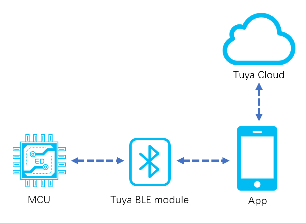
-
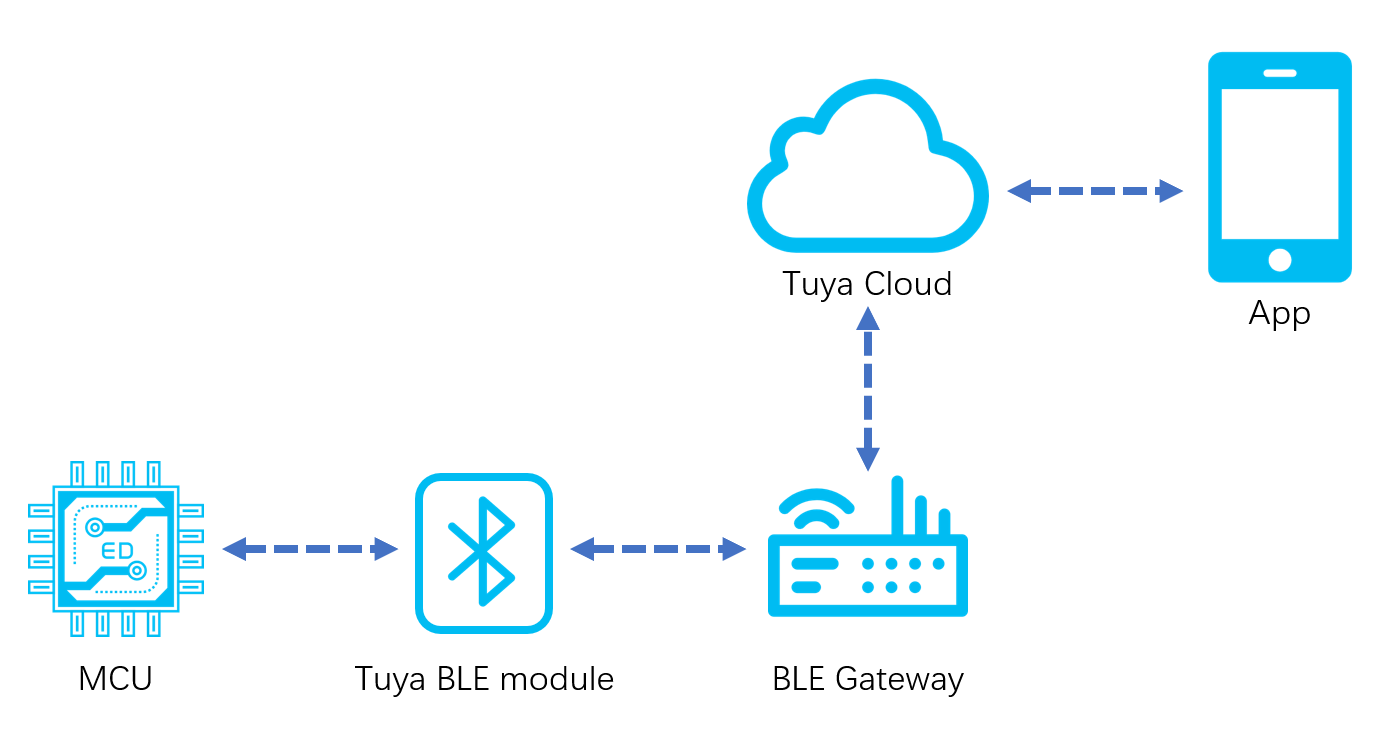
Bluetooth LE communication process with Bluetooth gateway is as follows:
Development process
The whole development process consists of product creation, hardware debugging, software development, and function debugging.
Step 1: Create products
This section describes product creation process. For specific procedures, see MCU Connection Solution.
-
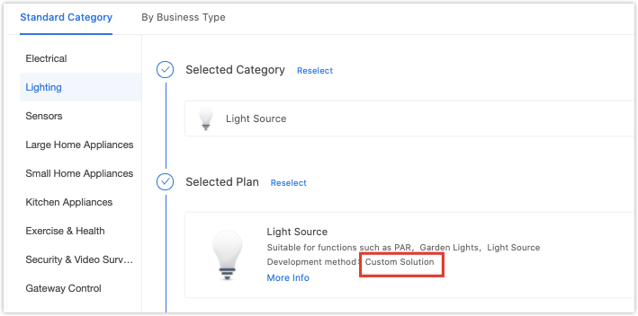
Log in to the Developer Platform and create a product. Select the desired product, and select Bluetooth LE for net pairing mode.
The general firmware of Tuya Bluetooth LE module integrates low power mode and standard power mode. You can select the mode according to the protocol commands.
- Standard power mode suits products that require an uninterruptible power supply.
- Low power mode suits battery-powered products that require low power consumption.
-
After finishing creation, you select the functions, panel, module, and firmware based on your product, and download the MCU development documents accordingly.
-
Select a module.
The platform recommends the common module models when you create a product. After selecting the module and firmware, you can purchase the module sample online. The hardware engineer will proceed with the board layout design. The documentation related to hardware development is as follows:
Note: if the power is supplied by batteries when the supply voltage is lower than normal working voltage, flash operation inside the chip might have an error, and firmware or user data might be modified abnormally. It can be avoided by the following two methods.
- When MCU detects that battery voltage is too low, cut off the working power supply of the module.
- When MCU detects that battery voltage is too low, disable the broadcast and system timer, and let the chip run in deep sleep mode. The minimum working voltage of the Telink module is 1.8V. MCU can be set to disable the module at 2.0V, which shall be slightly higher than 1.8V.
Step 2: Network configuration verification
When receiving the module, it is suggested that, before start coding, you run the provided module debugging assistant to check if the module can work properly. In MCU simulation mode, connect the module and configure the network for practice. Meanwhile, you can get familiar with the protocol interaction process, which will help you to proceed with the development debugging.
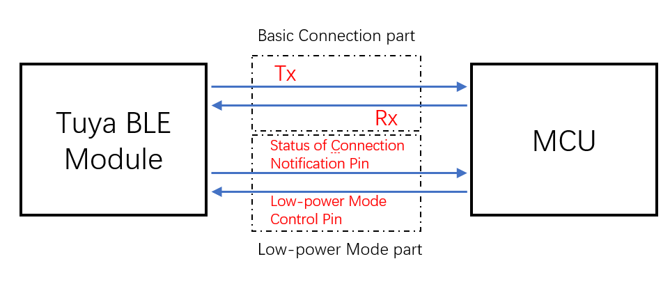
Tuya Bluetooth LE general serial port protocol architecture is as follows:
-
Low power mode control pin: currently, for general connection solution to door locks (use TYBN1 module and BK3431Q chip), it is the required control pin in coordination with MCU connection. For more information, see Tuya Universal Serial Port Protocol. For other general connection solutions, if the low power function is not used, TX and RX pins can complete the basic protocol interaction. If the low power function is used, you must connect the low power mode control pin of the module.
-
Status of connection notification pin: in low power mode, when mobile phone Bluetooth is connected, the GPIO outputs high electrical level. When it is disconnected, the GPIO outputs low electrical level.
Note: certain modules do not support this function. For more information, see Tuya Universal Serial Port Protocol. (Optional, silk screen varies by pin models, see datasheet for more details)
In MCU simulation mode, the debugging assistant simulates the MCU to automatically respond to the module with the correct protocol data. After you configure network through the mobile phone, you can test DP data reporting and sending. The procedure of operating the assistant and module network configuration is as follows. Before operation, you need to learn about the operation instruction of Tuya module debugging assistant. For beginners, you can refer to Module Debugging Assistant Instruction.
The connection diagram in MCU simulation mode of the debugging assistant is as follows:
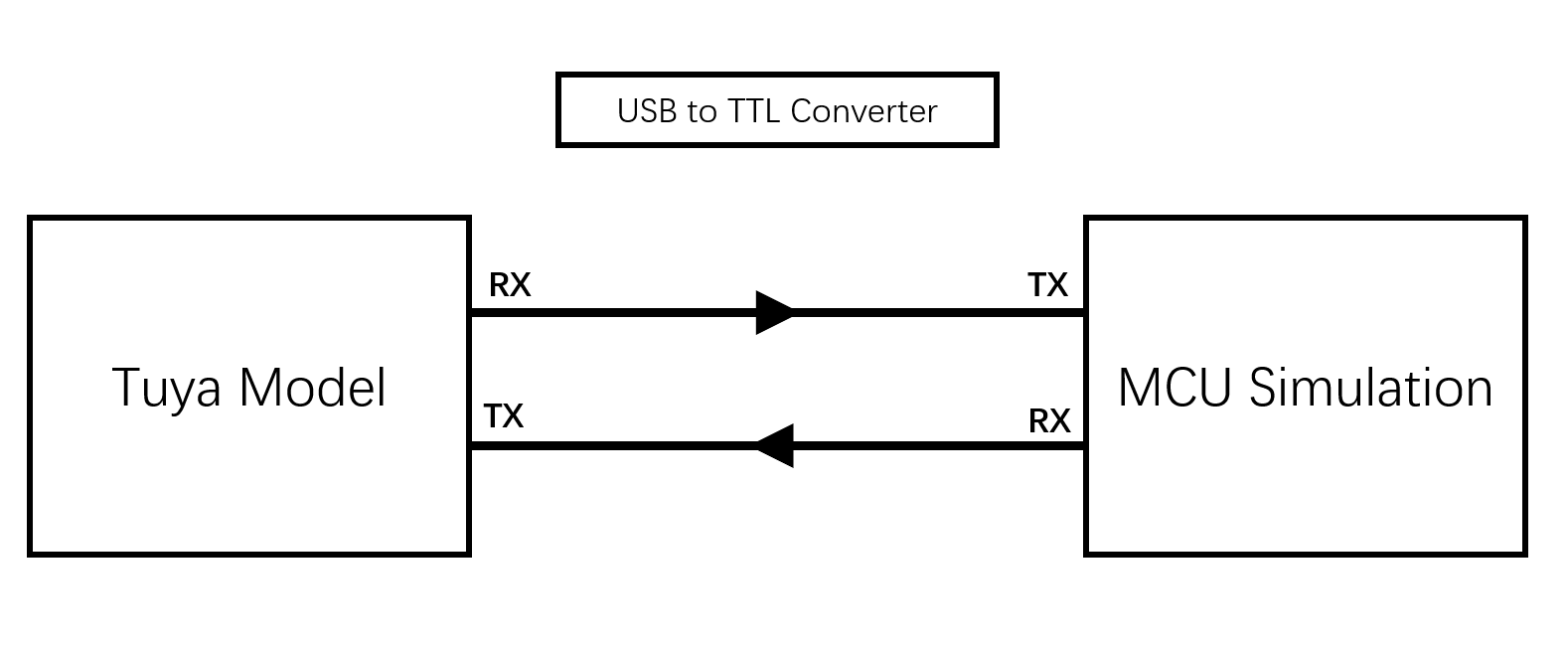
-
Based on the schematic diagram of the minimum system, you build the peripheral circuit of the module, and jump the wire directly in case of simple testing.
-
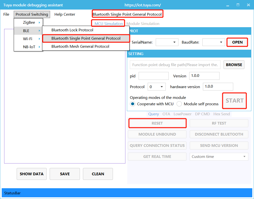
Open the debugging assistant in the development documents, and import the debugging file. Choose Bluetooth LE > Bluetooth Single Point General Protocol, and MCU Simulation.
-
Connect the module serial port to the computer through USB-to-TTL adapter, and select the corresponding serial port and Baud in the assistant. After you open the serial port and click Start, you will see the initial protocol interaction between the module and the host.
Note: Bluetooth LE module will constantly send heartbeat packets after power-on. When receiving the correct response, it will proceed with the initial protocol interaction. If the module does not send data after power-on, check if the peripheral circuit of the module is correct.
-
Click Reset, and the module Bluetooth will be disconnected. Unpair Bluetooth connection, clear offline cache information of the module, and then reboot.
Step 3: Software development
During hardware debugging, you will see a sequence of serial port protocol interaction data between the module and MCU. To understand this data, refer to the protocol documentation in the development documents. The protocol consists of basic protocol and function protocol.
-
The basic protocol is product neutral and shared by the modules. It consists of module initial command and certain extension function command.
-
The function protocol works to report and send commands based on the basic protocol, and specifies the DP data format. For more information, see Tuya Universal Serial Port Protocol.
There are two methods to connect the MCU to Tuya module protocol, migrating MCU SDK or connecting the protocol by yourself.
-
Connect the protocol by yourself: if the MCU resource is limited, or migrating MCU SDK is inapplicable, you can connect the protocol by yourself.
-
Migrate MCU SDK: if the MCU resource is sufficient, it is recommended to directly migrate MCU SDK, which facilitates the development process. MCU SDK in the development documents is the protocol application code in C language, and it can be directly imported to the MCU project. MCU SDK requirements for MCU hardware resources:
- 4 KB Flash sector.
- About 100 bytes of RAM. RAM is related to DP data length. If OTA function is configured, RAM must be greater than 260 bytes.
- 9-level nested function is adopted.
If the resource is limited, you can connect the protocol by yourself. The functions in the SDK package can act as references. For more information, see Tuya Universal Serial Port Protocol.
Step 4: Protocol verification
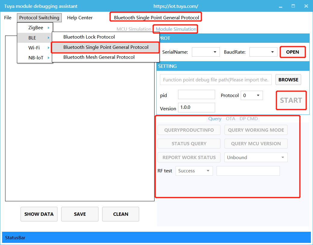
After migrating MCU SDK, you can use the module debugging assistant in module simulation mode to verify the MCU code. The operation is similar to MCU simulation mode. In the module simulation mode, the assistant automatically sends the initial data flow to verify whether the MCU response is correct, and send prompts for data error. After the initial interaction, you can test other extension functions.
Note: the module simulation mode only verifies the MCU serial port protocol, and does not support networking. After finishing test, connect the MCU to the actual module and proceed with joint network configuration debugging.
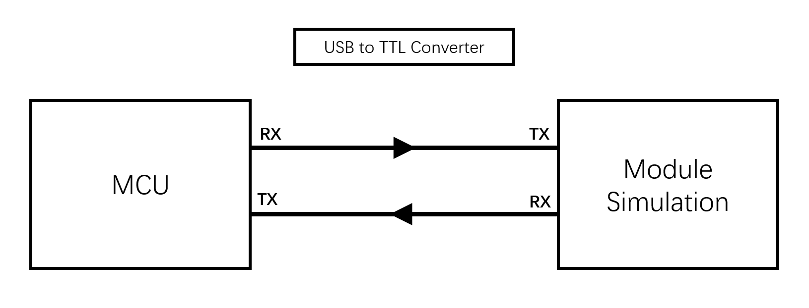
The connection diagram in module simulation mode of the debugging assistant is as follows:
Step 5: Joint debugging
After the assistant verifies the code, connect the MCU to the module and configure network on the app. You will enter function joint debugging. Joint debugging is used to test whether the DPs reporting and sending works properly. The links of useful tools adopted in the debugging are as follows:
- Query the background log: log in to the Developer Platform and enter Operation center. Query device background log according to its device ID.
- Online support center: Tuya provides online services. If the documentation cannot solve your problems, raise your questions online and our technical team will help you troubleshoot problems.
Is this page helpful?
YesFeedbackIs this page helpful?
YesFeedback


