TYLC3V Module Datasheet
Product Overview
After a period of service, this module will become deprecated due to product upgrades and iterations, user requirements, production inventory, or other reasons. To improve the compatibility of your smart devices and minimize the impact on your use, Tuya continues to provide webpage documentation of deprecated modules, but no longer maintains or updates the documentation. The content herein is for reference only.
If you have any questions, submit a ticket to contact Tuya or consult Tuya’s account manager to request support.
TYLC3V is a low-power built-in Bluetooth module developed by Hangzhou Tuya Information Technology Co., Ltd. It consists of a highly integrated Bluetooth chip (TLSR8267) and several peripheral electrical circuits, with a built-in Bluetooth network communication protocol stack and robust library functions.
TYLC3V also contains a low power-consuming 32-bit MCU, a Bluetooth 2.4 GHz radio, a 512 KB flash, a 16 KB SRAM, and nine multiplex I/O ports.
Features
-
Built-in low power-consuming 32-bit MCU, which can also be used as an application processor
-
Basic frequency: 48 MHz supported
-
Working voltage: 5–38 V (16–38 V by default)
-
Peripherals: five GPIOs
-
Bluetooth RF features
-
Compatible with Bluetooth 4.2
-
RF data rate: up to 2 Mbit/s
-
TX power: +7 dBm
-
RX sensitivity: –92 dBm
-
-
Built-in AES encryption for hardware
-
Onboard PCB antenna
-
Working temperature: –20°C to +105°C
Major application fields
- Intelligent LED
- Intelligent home
- Intelligent low-power sensor
Module Interfaces
Dimensions and Footprint
TYLC3V provides two rows of pins with a distance of 2.0 mm between every two pins.
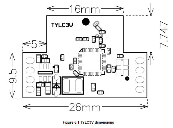
TYLC3V dimensions: 17.25 mm (W) x 26 mm (L) (see figure 2.1)
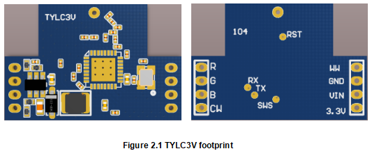
Pin definition
Table 2.1 describes the interface pins.
Table 2.1, TYLC3V interface pins
| Pin | Symbol | I/O Type | Functions |
|---|---|---|---|
| 1 | WW | I/O | PWM2_N, common I/O interface, which can be used for PWM output of the LED driver. It controls the warm white LED by default. |
| 2 | GND | P | Power supply reference ground pin |
| 3 | VIN | P | Power supply input pin |
| 4 | 3.3 V | P | Power supply output pin |
| 5 | CW | I/O | PWM4, common I/O interface, which can be used for PWM output of the LED driver. It controls the cold white LED by default. |
| 6 | B | I/O | PWM1, common I/O interface, which can be used for PWM output of the LED driver. It controls the blue LED by default. |
| 7 | G | I/O | PWM0, common I/O interface, which can be used for PWM output of the LED driver. It controls the green LED by default. |
| 8 | R | I/O | PWM5, common I/O interface, which can be used for PWM output of the LED driver. It controls the red LED by default. |
Pindicates power-supply pins and I/O indicates input/output pins.- When the WW pin is used for PWM output, its polarity is opposite to that of the R, G, B, and CW pins used for PWM output. If you have special requirements for the light color controlled by PWM output, contact our business manager.
Electrical Parameters
Absolute electrical parameters
Table 3.1 Absolute electrical characteristics
| Parameters | Description | Minimum value | Maximum value | Unit |
|---|---|---|---|---|
| Ts | Storage temperature | -40 | 125 | ℃ |
| VIN | Power supply voltage | -0.3 | 40 | V |
| Static electricity voltage (human model) | TAMB-25℃ | - | 2 | KV |
| Static electricity voltage (machine model) | TAMB-25℃ | - | 0.5 | KV |
Operating conditions
Table 3.2 Normal electrical conditions
| Parameters | Description | Min | Typ | Max | Unit |
|---|---|---|---|---|---|
| Ta | Working temperature | -20 | - | 105 | ℃ |
| VIN | Working voltage | 5* | - | 38 | V |
| VIL | I/O low-level input | VSS | - | 1 | V |
| VIH | I/O high input | 2.3 | - | 3.3 | V |
| VOL | I/O low-level output | VSS | - | 0.3 | V |
| VOH | I/O high-level output | 3 | - | 3.3 | V |
- The minimal value for the working voltage of the delivered module is 16 V by default. To change this value, you need to specify it in the order.
Power Consumption in Operating Mode
Table 3.3 TX power consumption during constant emission
| Symbol | Condition | Typ | Unit |
|---|---|---|---|
| Itx | Constant emission, with 0 dBm output power | 15 | mA |
| Irx | Constant receiving | 12 | mA |
| IDC | Mesh connected | 27 | mA |
| Ideepsleen | Sleep mode | 18 | uA |
RF Features
Basic RF Features
Table 4.1 Basic RF features
| Parameter | Description |
|---|---|
| Frequency band | 2.4 GHz ISM band |
| Radio standard | Bluetooth 4.2 |
| Data transmitting rate | 1 Mbps and 2 Mbps |
| Antenna type | Plug-in spring antenna |
RF Output Power
Table 4.2 TX power during constant emission
| Parameter | Min | Typ | Max | Unit |
|---|---|---|---|---|
| RF average output power | 3.8 | 7 | 8 | dBm |
| 20 dB bandwidth (1 M) | - | 1300 | - | KHz |
| 20 dB bandwidth (2 M) | - | 2600 | - | KHz |
RF RX sensitivity
Table 4.3 RX Sensitivity
| Parameter | Rate | Minimum Value | Typical Value | Maximum Value | Unit |
|---|---|---|---|---|---|
| RX sensitivity | 1Mbps | -93 | -92 | -90 | dBm |
| RX sensitivity | 2Mbps | -90 | -89 | -86 | dBm |
| Frequency offset error | 1Mbps | -300 | - | +300 | KHz |
| Frequency offset error | 2Mbps | -200 | - | +200 | KHz |
| Co-channel interference suppression | - | - | -7 | - | dB |
Antenna Information
Antenna type
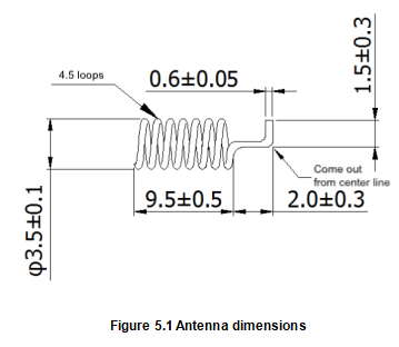
TYLC3V uses the plug-in spring antenna working in the 2.4 GHz Wi-Fi band for the PCB.
Figure 5.1 shows the antenna dimensions.
Antenna Interference Reduction
To ensure optimal RF performance, it is recommended that there be a space of at least 15 mm between the module antenna and other metal parts. The antenna must be far away from the PCB and high devices, especially high metal parts.
If the distance is too small, the electromagnetic wave radiated by the antenna generates the induced electromotive force at the edge of the PCB. In this case, an induced magnetic field is generated, which consumes some energy of the original electromagnetic field, reducing the antenna radiation efficiency. It is recommended that the antenna be at least 15 mm away from the PCB.
Packaging and Production Instructions
Mechanical Dimensions and Size of the Back Pad
Production Instructions
Storage conditions of a delivered module are as follows:
- The anti-moisture bag is placed in an environment where the temperature is under 30°C and the relative humidity is under 85%.
- The shelf life of a dry-packaged product is six months from the date when the product is packaged and sealed.
Precautions:
- Throughout the production process, each involved operator must wear an electrostatic ring.
- During the operation, strictly protect the module from water and strains.
Is this page helpful?
YesFeedbackIs this page helpful?
YesFeedback


