Flash and Authorize FR801xH Series Modules
This topic describes how to flash the firmware and authorize FR801xH series modules.
Firmware flashing
You can flash firmware using a USB to UART converter or a J-Link debug probe.
The difference between these two methods:
- USB to UART converter: supports flashing and full chip erase.
- J-Link debug probe: supports write only, not erase.
Keil + J-Link debug probe
-
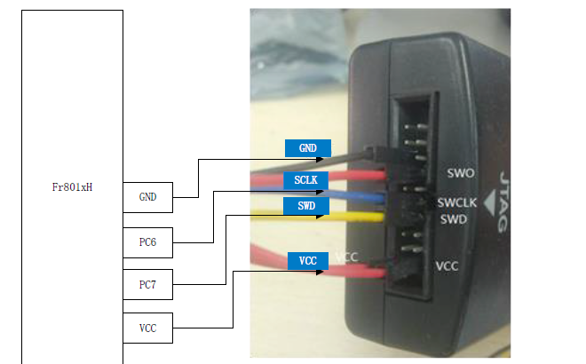
Connect hardware
Connect the J-Link debug probe to the development board as shown below.
-
Configure Keil
-
Install Keil5.
-
Install the Cortex-M3 software pack on Keil.
-
Copy the
Fr801xH SDK/Tools/FR8010H.FLMfile to the directory\Keil_v5\ARM\Flashto enable online downloading of Fr801xH J-link. -
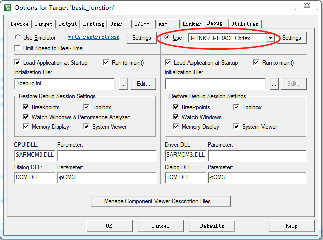
Set up Keil.
-
Select J-Link as the debugger.
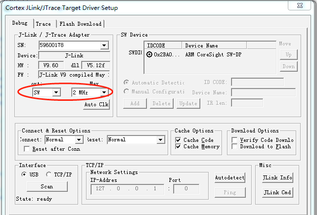
-
Set the debug port to SW.
-
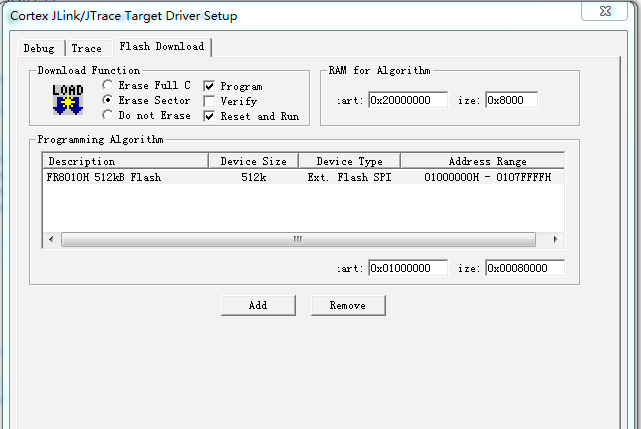
Click the Flash Download tab, and then click Add. Select the configuration file and click OK.
-
Select Use Target Driver for Flash Programming.
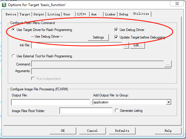
-
Then, you can flash firmware to the board using Keil.
Flashing tool + USB to UART converter
If the J-Link debug port on the chip is reused, or the system enters sleep mode, the J-Link based firmware flashing cannot work. In this case, you can use the dedicated flashing tool and a USB to UART converter to flash firmware. Once the chip is powered on, its boot program will attempt to communicate with external tools through the serial port. After a successful handshake is established, you can proceed with firmware flashing.
| Chip pin | USB to UART converter pin |
|---|---|
| PA3 (TXD) | RX |
| PA2 (RXD) | TX |
| VCC | VCC3.3V |
| GND | GND |
-
Install the driver for your USB to UART converter.
-
Open the flashing tool.
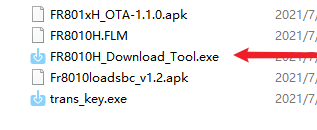
Select the port number, import the DAT file (the binary file to flash), turn on the serial port, and wait for the connection to complete.
-
Connect the TX and RX on the USB to UART converter to the PA2 (RX) and PA3 (TX) on the chip.
-
Connect the GND and VCC pins on the USB to UART converter to the corresponding pins on the chip. After the chip is connected to the flashing tool, you can click Erase all and then click Write all to flash firmware to the chip.
To prevent unexpected electrical current flow from the TX on the USB to UART converter to the chip, make sure to connect the wires as specified in steps 2 and 3.
-
After flashing, reset FR8018HA. If information is output from the serial port, it means the firmware runs properly.
To output logs, enable the following two macros.
#define TUYA_BLE_LOG_ENABLE 1
#define TUYA_APP_LOG_ENABLE 1
Flashing and authorization
Get the license
For more information, see Authorize Bluetooth LE Series Modules.
Flashing and authorization
-
Connect UART2 on the chip to a USB to UART converter.
-
Open Cloud Module Burning Authorization Platform, and enable Only Auth.
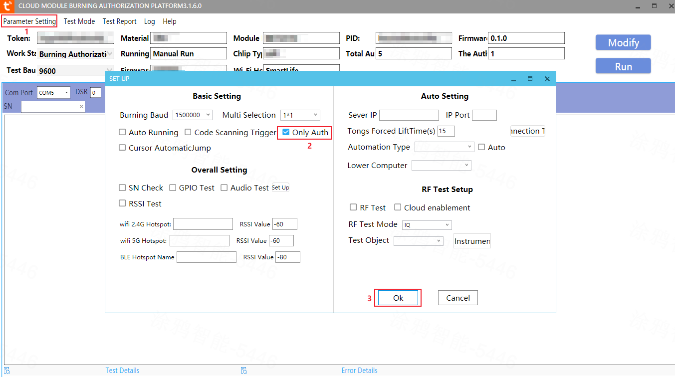
The code specifies the baud rate and UART2 for authorization. Ensure that you set the software according to the code.
   uint32_t ty_uart2_init(void)
   {
       system_set_port_pull(GPIO_PA2, true);
       system_set_port_mux(GPIO_PORT_A, GPIO_BIT_2, PORTA2_FUNC_UART1_RXD);
       system_set_port_mux(GPIO_PORT_A, GPIO_BIT_3, PORTA3_FUNC_UART1_TXD);

       uart_init(UART1, BAUD_RATE_115200);
       NVIC_EnableIRQ(UART1_IRQn);
       uart2_is_init = true;
       return TUYA_BLE_SUCCESS;
   }
Is this page helpful?
YesFeedbackIs this page helpful?
YesFeedback


