Flash and Authorize WR Modules
This topic describes two solutions about how to flash firmware to and authorize WR series modules.
Background information
After the module SDK firmware development is completed, you need to flash and authorize the module to enable connection to the Tuya Cloud. Tuya provides the following two flashing and authorization methods for different scenarios.
-
An integrated solution for flashing and authorization. This solution is made to flash and authorize modules on the Cloud Module burning Authorization Platform, which is suitable for the release stage.
-
Separated solutions for flashing and authorization. This solution is made to flash modules with chip burning tools and authorizes modules on the Cloud Module burning Authorization Platform, which is suitable for the development stage.
Supported chips
Applicable to the WR Series Module with the core chip of RTL8710BN. The following models are included.
Binaries
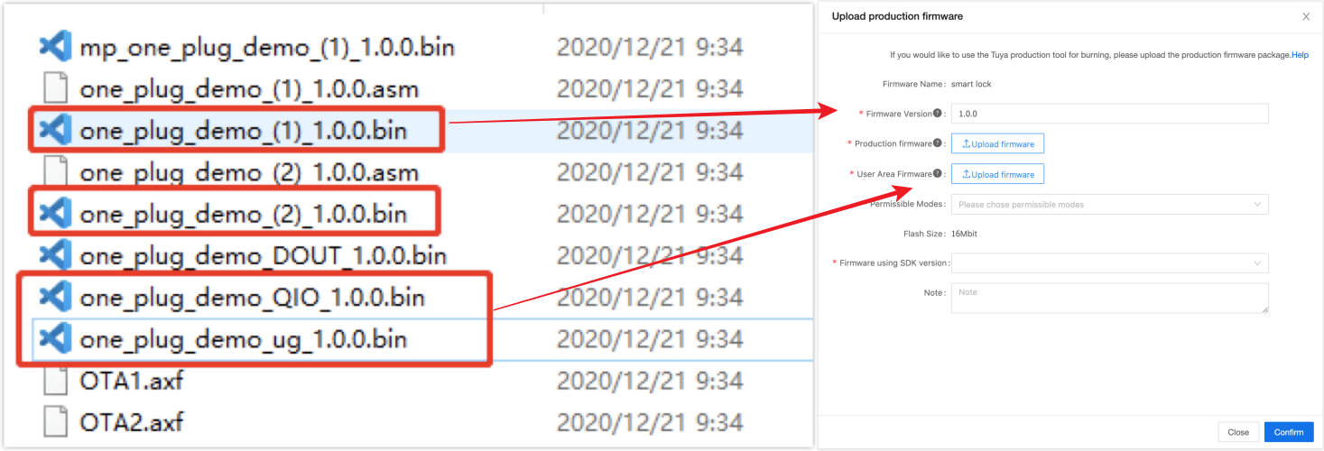
After this type of chip is compiled, four kinds of .bin files are generated as shown below:
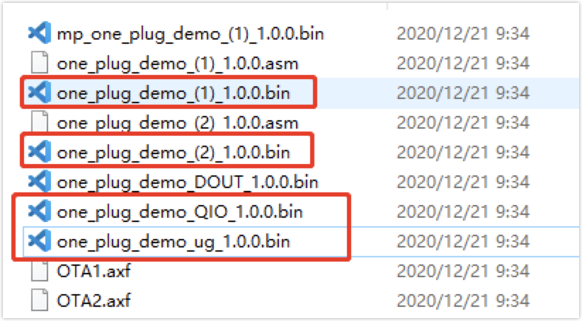
- one_plug_demo_(1)_1.0.0.bin: user area firmware 1. The start address is0xB000.
- one_plug_demo_(2)_1.0.0.bin: user area firmware 2. The start address is0xB000.
- one_plug_demo_QIO_1.0.0.bin: production firmware (bootloader + system data + OTA1 + OTA2).
- one_plug_demo_ug_1.0.0.bon: upgrade firmware (OTA1 + OTA2).
Things to note
When the following circumstances occur during firmware compiling, run the command sudo apt-get install gawk to install gawk dependency.
Method 1: An integrated solution for flashing and authorization
This solution is suitable for the release stage. Since the Tuya module must be authorized to connect to the Tuya platform, the authorization step cannot be omitted.
The overall process of this solution is as follows:
- Upload the compiled firmware to the Tuya Developer Platform.
- A firmware key is generated on the platform, and an authorization code is generated based on the firmware key.
- flash and authorize the modules on the Cloud Module burning Authorization Platform.
Prepare hardware
Hardware preparation includes serial port assistant, any module equipped with chip platform RTL8710BN (using WR3 Module Datasheet as an example in this topic), and hardware connection diagram.
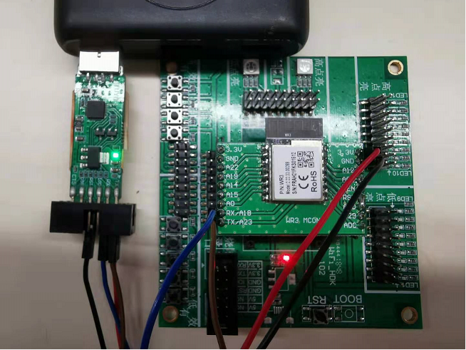
| Module pin | Serial pin |
|---|---|
| RXD1 | TX |
| TXD1 | RX |
| VCC | VCC3.3V |
| GND | GND |
Upload firmware
-
In step 3 Hardware Development of the product development process on the Tuya Developer Platform, click Add custom firmware.
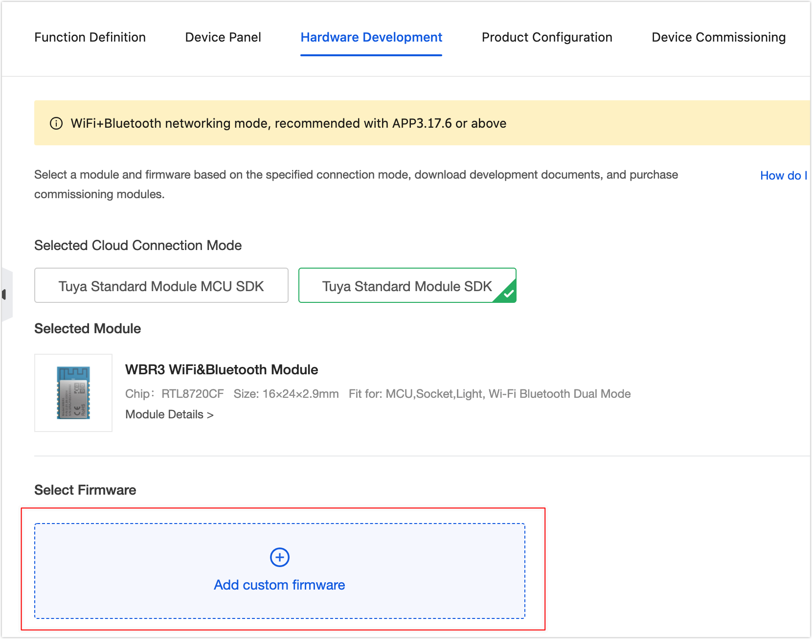
-
Enter the firmware parameters and click OK.
Parameter Description Firmware identifier It must be consistent with the name of the compiled firmware. Firmware type The module firmware Other parameters Enter as required. 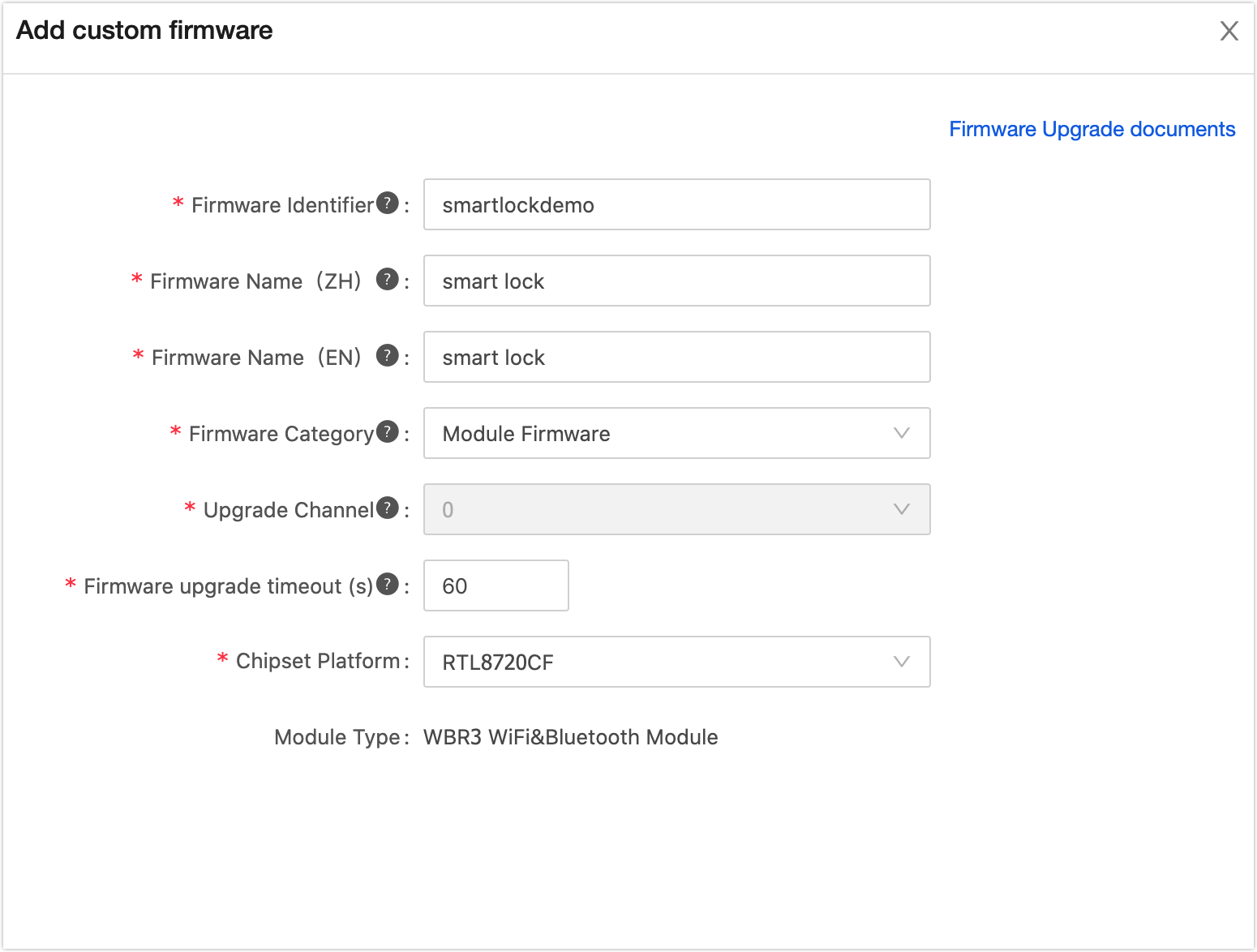
-
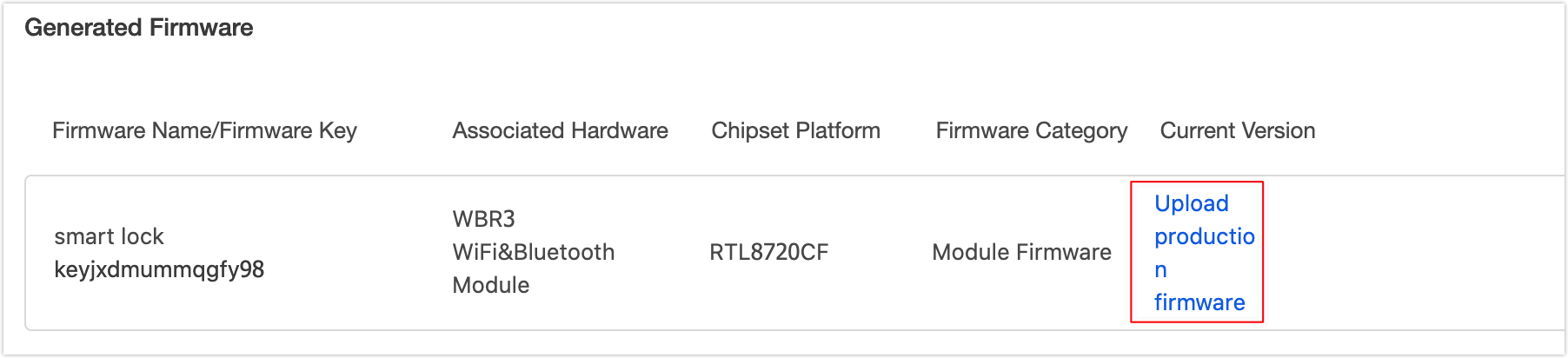
In the Generated Firmware area, click Upload production firmware.
-
Upload the firmware and click Confirm.
- Production firmware: Upload the .bin file with QIO in the file name.
- User area firmware: Upload the .bin file with ug in the file name.
Get authorization code and flash
Get the authorization code on the platform according to the PID, and download the Cloud Module burning Authorization Platform in reference to flashing and Authorization.
The flashing steps are:
- Power off the module in the first place.
- On the Cloud Module burning Authorization Platform, enter the authorization code and click Run.
- After the flashing is completed, power on the module.
Method 2: Separated solutions for flashing and authorization
This solution is suitable for the development stage. The feature of this solution is to authorize once and flash repeatedly. If the module has already been authorized once, you need only to modify and flash the firmware demo to make the module work properly.
Prepare hardware
Hardware preparation includes serial port assistant, any module equipped with chip platform RTL8710BN (using WR3 Module Datasheet as an example in this topic), and hardware connection diagram.
Note:
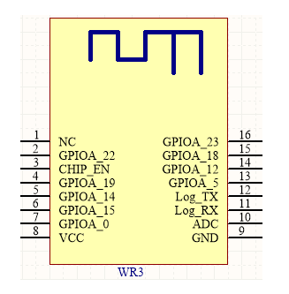
- Hardware connection description: Log_TX and RST pins should be short-connected, Log_TX needs to be connected to serial port RX, and Log_RX needs to be connected to serial port TX.
- Description of the module entering flashing status: Connect Log_TX to GND before power on, and connect Log_TX to serial port RX after power on.
| Module pin | Serial pin |
|---|---|
| Log_TX | RX |
| Log_RX | TX |
| VCC | VCC3.3V |
| GND | GND |
 |
Prepare software
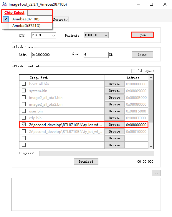
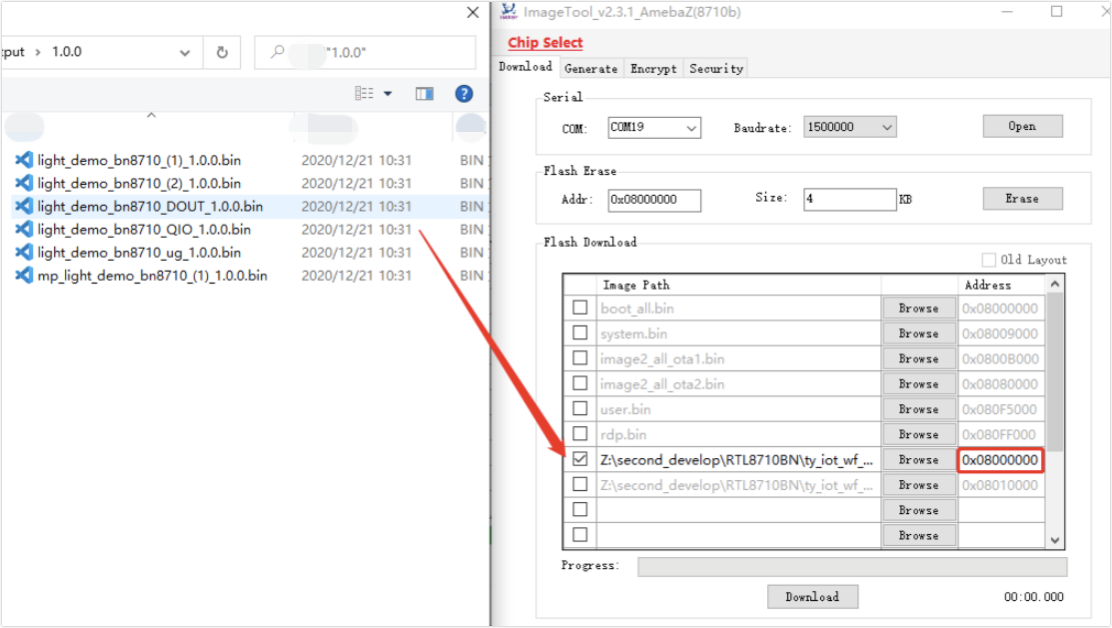
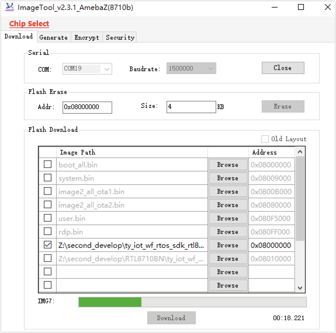
Download the RTL8710BN chip burning tool. Open the chip burning tool and it is shown as follows.
Things to note
-
Chip selection: Use RTL8710BN platform to select AmebaZ (8710B), and use RTL8720DN platform to select AmebaZ (8710D).
-
Load the binaries: For the production firmware, select the .bin file with QIO in the file name, and enter 0x8000000 as the address. For the production firmware, select the .bin file with ug in the file name, and enter 0x0800B000 as the address.
Download description
Method 1: flash the user area firmware
Note: Connect Log_TX to GND before the module is powered on, and connect Log_TX to serial port RX after the module is powered on.
The prerequisite for this flashing method is that the boot firmware already exists.
-
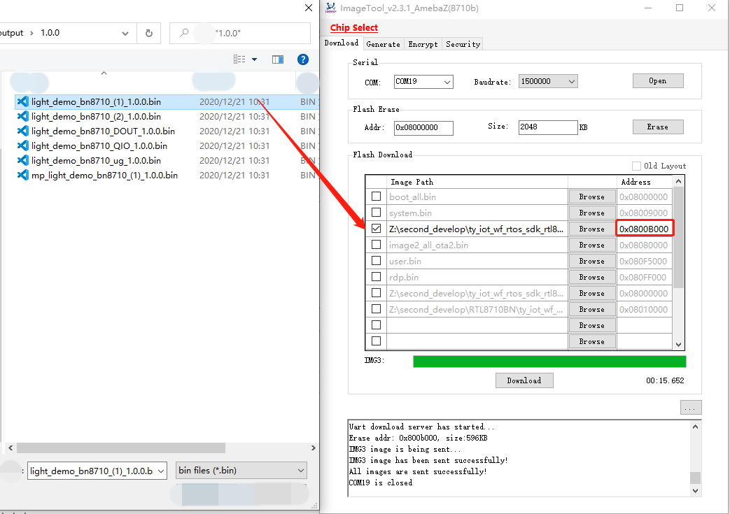
Select the chip and load the .bin file shown in the diagram, and enter 0x0800B000 as the address.
-
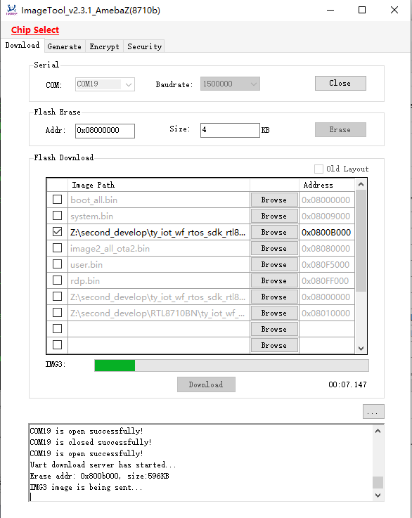
Click Download.
Method 2: flash the whole firmware
Note: Connect Log_TX to GND before the module is powered on, and connect Log_TX to serial port RX after the module is powered on.
-
As it is shown below, use an empty slice (without boot firmware) to load the QIO file, and enter 0x080000000 as the address.
-
Click Download.
-
After the flashing is completed, switch to the user area firmware and enter
ATSC+Enterafter power on. It is shown as follows.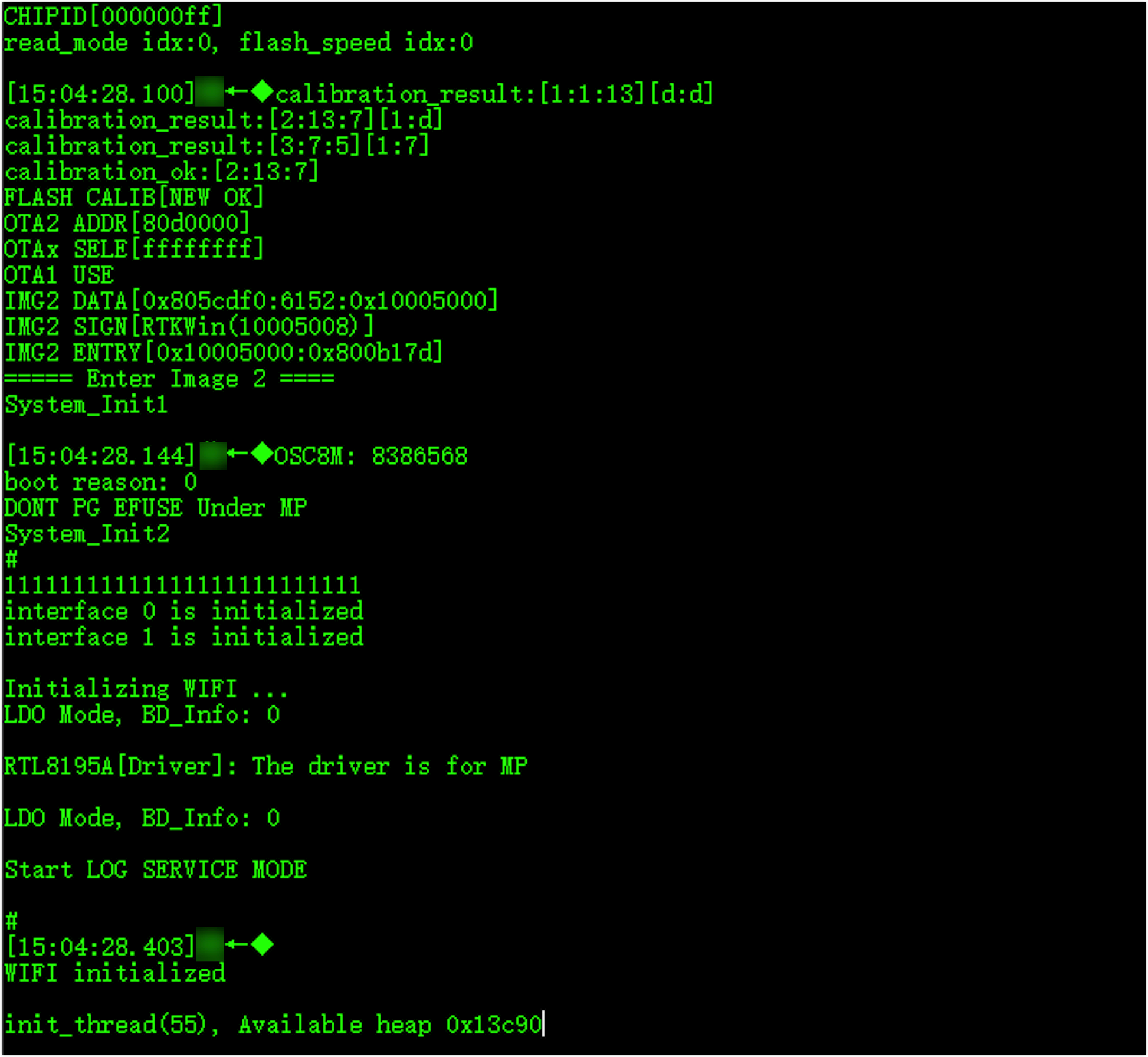
-
The module receiving the
ATSC+Entercommand and printing the log as shown below indicates that the application code has been successfully started, and it can run properly after power on again.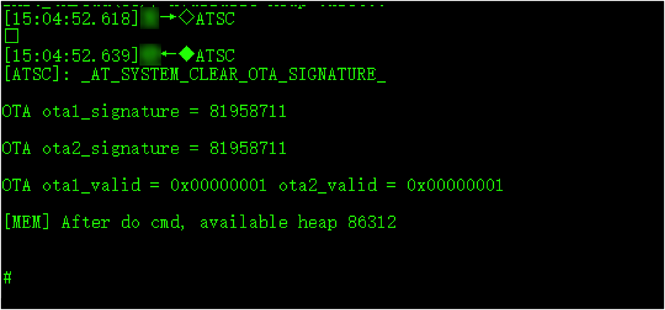
Is this page helpful?
YesFeedbackIs this page helpful?
YesFeedback


