Wi-Fi Low-Power Device Solution
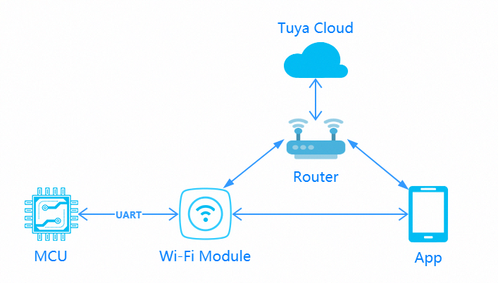
Many battery-powered products in the market, such as security sensors, feature low power, small size, and weak interaction. Wi-Fi low power solution is designed for this product category. The communication schematic diagram is as follows. You can quickly complete the MCU connection and implement device networking through Tuya Wi-Fi low power connection protocol. Tuya provides complete development services from modules, apps to cloud services.
Compared to Wi-Fi general module solution, Wi-Fi low power module tailors and optimizes the software. After sending data, MCU will power the module off.
Development process
Step 1: Create products
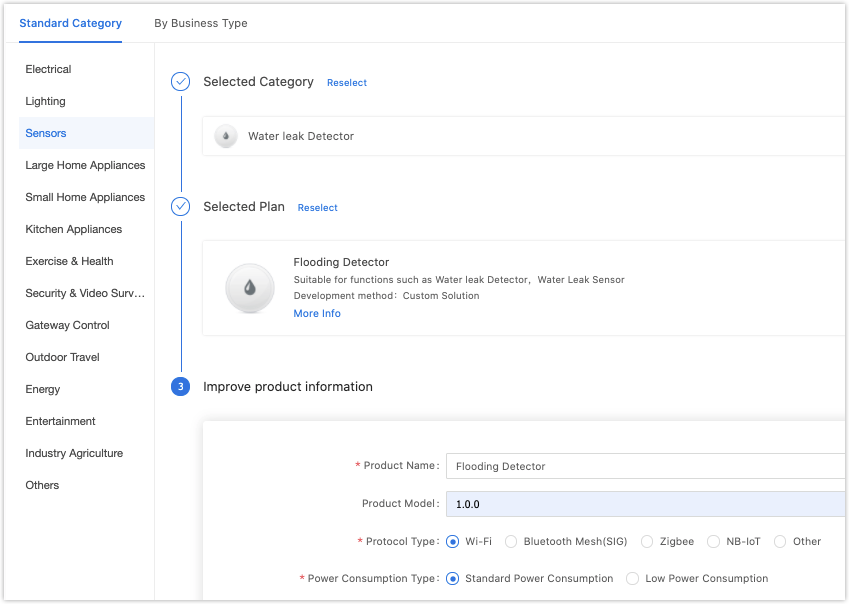
Log in to the Developer Platform and create a product. Select the desired product, and select Wi-Fi for net pairing mode. After finishing creation, you select the functions, panel, module, and firmware based on your product, and download the MCU development documents accordingly.
For certain product categories, a power type is an option. You select the standard power for products powered from mains electricity. For battery-powered products, low power is recommended.
Note: Power type determines the subsequent selection of module and firmware.
You can find the specific description of creating products in MCU Connection Solution. See the section of Product creation.
Common module
The platform recommends the common module models when you create a product. The recommended module models for low power Wi-Fi general solution are as follows:
-
Espressif: E2S and E3S. Firmware key: keyvw8xqm89v****
-
Xradio: XR1, XR2, and XR3. Firmware key: keycnw55p5k7****
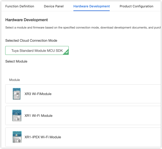
After selecting the module and firmware, you can purchase the module sample online. The hardware engineer will proceed with the board layout design. See the documentation related to hardware development in the documentation center.
Datasheet: TYWE1S Module Datasheet
Schematic diagram of the minimum module: TYWE1S Module
Note:
- Wi-Fi low power module consumes less power than Wi-Fi general module. The peak electric current reaches over 400 mA (sustained current in microseconds). Consider the electric allowance during power design.
- The low power mode of the Wi-Fi module is achieved by power-off. The MCU is designed to control module power switching.
Step 2: Network configuration verification
When receiving the module, it is suggested that, before start coding, you run the provided module debugging assistant, and connect the Wi-Fi module in MCU simulation mode to check if the module can work properly. Meanwhile, you can get familiar with the protocol interaction process, which will help you to proceed with development debugging.
In the MCU simulation mode, the debugging assistant simulates the MCU to automatically respond to the module with the correct protocol data. After you configure the network through the mobile phone, you can test DP data reporting and sending. The procedure of operating the assistant and module network configuration is as follows. Before the operation, you need to learn about the operation instruction of the Tuya module debugging assistant. For beginners, see Module Debugging Assistant Instruction.
-
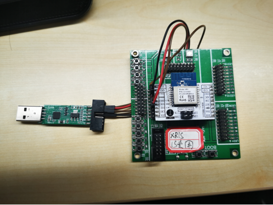
Based on the schematic diagram of the minimum system, you build the peripheral circuit of the module and jump the wire directly in case of simple testing.
-
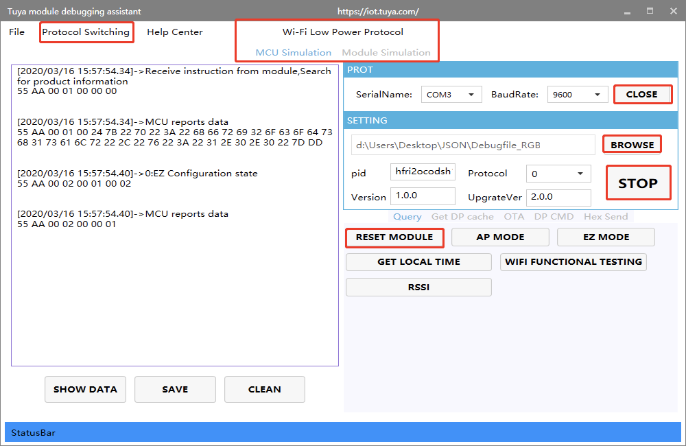
Open the debugging assistant in the development documents, and import the debugging file. Select the Wi-Fi low power protocol and MCU simulation mode.
-
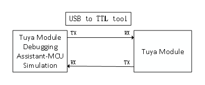
Connect the module serial port to the computer through USB-to-TTL adapter, and select the corresponding serial port and Baud in the assistant. After you open the serial port and click Start, you will see the initial protocol interaction between the module and the host.
Note: Wi-Fi low power module will send command
01after power on. When receiving the correct response, it will proceed with the initial protocol interaction. If the module does not send data after power on, check if the peripheral circuit of the module is correct. -
Click Reset Module, and the module enters network configuration mode. The module supports two network configuration modes, EZ and AP (The difference between EZ and AP modes). When you click Reset, the mode will be switched. Configure network on the app according to the status. See the app operation instruction for network configuration operation.
Step 3: Software development
During hardware debugging, you will see a sequence of serial port protocol interaction data between the module and MCU. To understand this data, refer to the protocol documentation in the development documents.
The protocol consists of a basic protocol and function protocol. The basic protocol is product-neutral and shared by the modules. It consists of a module initial command and certain extension function command. The function protocol works to report and send commands based on the basic protocol and specifies the DP data format.
The basic protocol is updated in real-time in the documentation center. See Serial Port Protocol.
There are two methods to connect the MCU to the Tuya module protocol, migrating MCU SDK, or connecting the protocol by yourself.
Connect the protocol by yourself
If the MCU resource is limited or migrating MCU SDK is inapplicable, you can connect the protocol by yourself.
Migrate MCU SDK
If the MCU resource is sufficient, it is recommended to directly migrate MCU SDK, which facilitates the development process. MCU SDK in the development documents is the protocol application code in C language, and it can be directly imported to the MCU project. The SDK requirements for MCU hardware resources: 4 KB flash, about 100 bytes of RAM. RAM is related to DP data length. For example, OTA function takes more than 260 bytes. A 9-level nested function is adopted. If the resource is limited, you can connect the protocol by yourself. The function in the SDK package can act as references.
MCU SDK migration tutorial: MCU SDK Migration
Power-off mechanism
Compared to the general solution, during network configuration, if the module does not connect to the cloud within 3 minutes, it will automatically enter low power mode.
The module will send:
55 aa 00 03 00 01 01
| Networking Status | Description | Status Value | LED Display |
|---|---|---|---|
| Status 6 | Wi-Fi device is in low power mode | 0x05 |
Off |
Step 4: Protocol verification
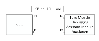
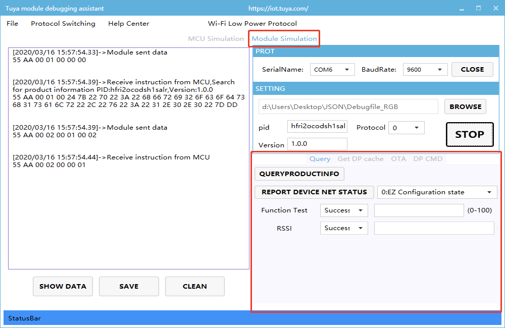
After migrating MCU SDK, you can use the module debugging assistant in module simulation mode to verify the MCU code. The operation is similar to the MCU simulation mode. In the module simulation mode, the assistant automatically sends the initial data flow to verify whether the MCU response is correct, and send prompts for data error. After the initial interaction, you can test other extension functions.
Note: The module simulation mode only verifies the MCU serial port protocol, and does not support networking. After finishing the test, connect the MCU to the actual module and proceed with joint network configuration debugging.
Step 5: Joint debugging
After the assistant verifies the code, connect the MCU to the module, and configure the network on the app. You will enter function joint debugging. Joint debugging is used to test whether the DPs reporting and sending work properly. The links of useful tools adopted in the debugging are as follows:
Query the background log: log in to the Developer Platform and enter Operation center. Query device background log according to its device ID.
Online support center: Tuya provides online services. If the documentation cannot solve your problems, raise your questions online and our technical team will help you troubleshoot problems.
FAQ
Remedy UART defect
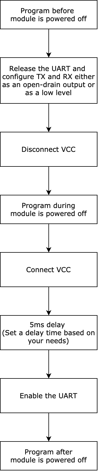
For the MCU that can control the on/off of the module, its TX and RX are idle high in most hardware designs. Therefore, the TX and RX on the MCU are generally configured as push-pull output and input respectively. This will cause the TX and RX to output a low current. When the module is disconnected from the VCC, it cannot be powered off completely due to the low current from the TX and RX on the MCU. This might cause some problems with hardware operation. To resolve the current sink problem without modifying the circuit, in MCU programming, you can disable the serial port when the module is powered off. Configure the TX and RX either as an open-drain output in high impedance or as a low level. If the TX or RX is connected to a pull-up resistor, it must be configured as low level.
-
The following sequence diagram shows how the MCU controls the on/off of the module.
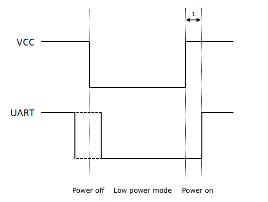
We recommend you set
tto five milliseconds. You can adjust the time based on your hardware. Note that if thetis set too short, the module might not start properly. -
The following block diagram shows how the MCU controls the on/off of the module.
Is this page helpful?
YesFeedbackIs this page helpful?
YesFeedback


