Serial Communication Protocol
The following figure shows how Tuya’s Zigbee module communicates with a third-party MCU.

Serial communication parameters
-
Baud: 9600/115200
-
Data bit: 8
-
Parity check: none
-
Stop bit: 1
-
Data flow control: none
-
Supply voltage: Tuya’s Zigbee module and the MCU are supplied by 3.3V DC.
The following table lists the pin definitions.
Module model TX on the module RX on the module Module wakes up MCU (low power version) MCU wakes up module (low power version) ZS3L PA5 PA6 PC1 PA3 TYZS3 PA0 PA1 PF5 PA2 TYZS5 PA0 PA1 PA4 PA3 ZTU PB1 PB7 PB4 PB5/PD2 ZT5 PB1 PB7 PB4 PB5/PD2 ZT3L PB1 PB7 PB4 PB5/PD2
Sleep and wake-up mode
-
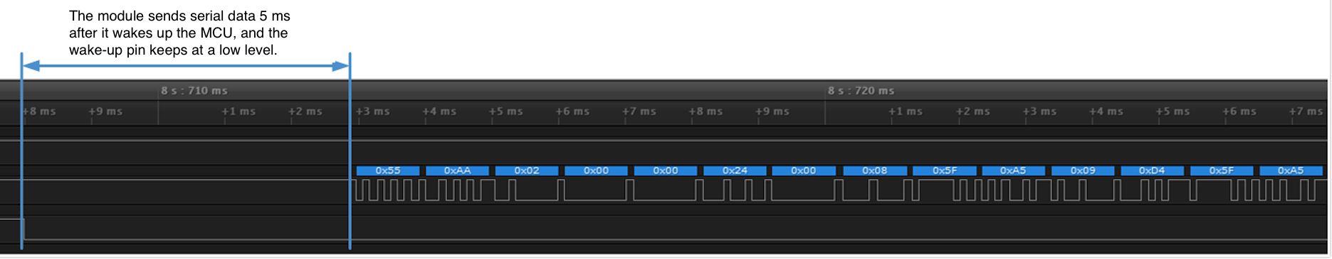
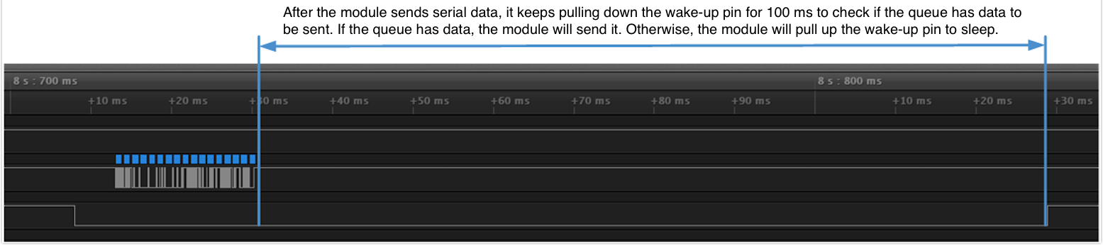
Low-power devices with sleep mode: Reserve two GPIOs on the Zigbee module and the MCU to wake up the MCU and module by level triggered interrupt. Each time before the Zigbee module or the MCU initiates a command, they will do a handshake. For more information about the wake-up method, see the following figure.
-
Electrical devices that do not support sleep mode: The serial port keeps listening for connection attempts, so the connection to I/O1 and I/O2 is not necessary.
-
The wake-up initialization time may differ for the module and the MCU. The interval between the level trigger and the serial data transmission can be set to a value from 3 ms to 300 ms, defaulting to 5 ms.
-
The MCU wakes up the module: You can pull down the wake-up GPIO for 1 to 10 milliseconds before data sending. The module is awake as the wake-up GPIO keeps low, but the maximum wake-up time is 2 minutes. To reduce consumption, the module enters sleep mode 300 to 550 milliseconds after the GPIO is high.
-
After the module is awake continuously for more than 2 minutes, it will automatically restart.
-
When an MCU wakes up the ZT series module, you need to set a delay of at least 10 milliseconds before data sending when the GPIO is low.
The firmware supports wake-up by pulses. The MCU sends a low pulse to the wake-up GPIO lasting for 1 to 5 milliseconds before data sending. For the ZT series module, the low pulse should last 10 milliseconds. When the wake-up GPIO keeps low, the power consumption of the module will increase. This pulse wake-up method can reduce consumption. See the following sample code.
	set_gpio_low();
	delay(1);
	set_gpio_high();
	uart_send_buffer();
Auto-baud detection
The module identifies the baud rate of the connected MCU on the first communication and the end product test process. The Zigbee module first queries the MCU for the PID and the MCU firmware version at the baud of 9600. Make sure not to wake up and send data to the Zigbee module before the baud rate detection.
- If the MCU responds correctly, the baud will be automatically set to 9600.
- If the MCU fails to respond, the module will query the MCU at the baud of 115200. If the MCU responds correctly, the baud will be set to 115200. Otherwise, the module will switch the baud to 9600 and repeat the query at different baud. The interval between queries is one second.
- After the module determines the baud rate, you cannot change it to another value.
Frame format
| Front | Ver | Cmd | Length | Data | Check |
|---|---|---|---|---|---|
| Header | Version | Command | Data length | Data | Checksum |
| Field | Bytes | Description |
|---|---|---|
Front |
2 | It is fixed to 0x55aa. |
Ver |
1 | The version of the serial protocol. |
Seq |
2 | The sequence number is a counter used to keep track of every byte sent outward by a host. It ranges from 0 to 0xFFF0. Once the sequence number reaches 0xFFF0, it loops back to 0. |
Cmd |
1 | Frame type |
Length |
2 | The payload length. |
Data |
Depends on data | The payload data. |
Check |
1 | Start from the header, add up all the bytes, and then divide the sum by 256 to get the remainder. |
The Length is determined by the length of a single packet transmitted by Tuya’s Zigbee module. The transport layer reassembles the packet as it streams the data contents to the receiving application. The protocol defined by Tuya specifies the maximum packet length is 62 bytes.
Command index
| Command | Description | Mains-powered version | Low-power version | Scene control version |
|---|---|---|---|---|
| 0x00 | The module notifies the MCU of factory reset initiated by the mobile app. | ✔ | ✔ | ✔ |
| 0x01 | The module requests the product information from the MCU. | ✔ | ✔ | ✔ |
| 0x02 | The module reports the current network status to the MCU. | ✔ | ✔ | ✔ |
| 0x03 | The MCU sends a configuration command to the Zigbee module. | ✔ | ✔ | ✔ |
| 0x04 | The module sends a command to the MCU. | ✔ | ✔ | ✔ |
| 0x05 | The MCU responds to a command. | ✔ | ✔ | ✔ |
| 0x06 | The MCU proactively reports status to the module. | ✔ | ✔ | ✔ |
| 0x07 | Reserved command. | ✔ | ✔ | ✔ |
| 0x08 | The MCU initiates a test of the radio frequency (RF) performance. | ✔ | ✔ | ✔ |
| 0x09 | The module requests the key configuration from the MCU. | ✘ | ✘ | ✘ |
| 0x0a | The MCU instructs the module to run a specific scene. | ✘ | ✘ | ✔ |
| 0x0b | The module requests the MCU firmware version. | ✔ | ✔ | ✔ |
| 0x0c | The module notifies the MCU of an OTA firmware update. | ✔ | ✔ | ✔ |
| 0x0d | The MCU requests to download the updates. | ✔ | ✔ | ✔ |
| 0x0e | The MCU returns the update result. | ✔ | ✔ | ✔ |
| 0x20 | Query Zigbee network status. | ✔ | ✔ | ✔ |
| 0x24 | The MCU requests to sync clock time with the server time. | ✔ | ✔ | ✔ |
| 0x25 | MCU requests gateway connection status. | ✔ | ✔ | ✘ |
| 0x26 | The MCU instructs the module to set the Zigbee network policy parameters. | ✔ | ✔ | ✘ |
| 0x27 | The module sends the MCU the DP data over broadcast. | ✔ | ✔ | ✔ |
| 0x28 | The module instructs the MCU to report DP data. | ✔ | ✔ | ✔ |
| 0x29 | When receiving beacon signals after power-on, the module instructs the MCU to enter the test mode. | ✔ | ✔ | ✔ |
| 0x2a | The module sends a group control command to the MCU. | ✔ | ✔ | ✘ |
| 0x2b | Set the time that the module should wait after it wakes up the MCU. | ✘ | ✔ | ✘ |
| 0x41 | The module sends the kid, gid, and sid to the MCU. |
✘ | ✘ | ✔ |
| 0x42 | The MCU sends multicast messages with standard commands. | ✘ | ✘ | ✔ |
| 0x43 | The MCU sends multicast messages with private commands. | ✘ | ✘ | ✔ |
All data greater than one byte is transmitted in big-endian format.
Serial communication model
Command transmission
One command is sent by one party and received by the other party synchronously. That is, one party sends a command and waits for a response from the other party.
For more information, see the protocol details.
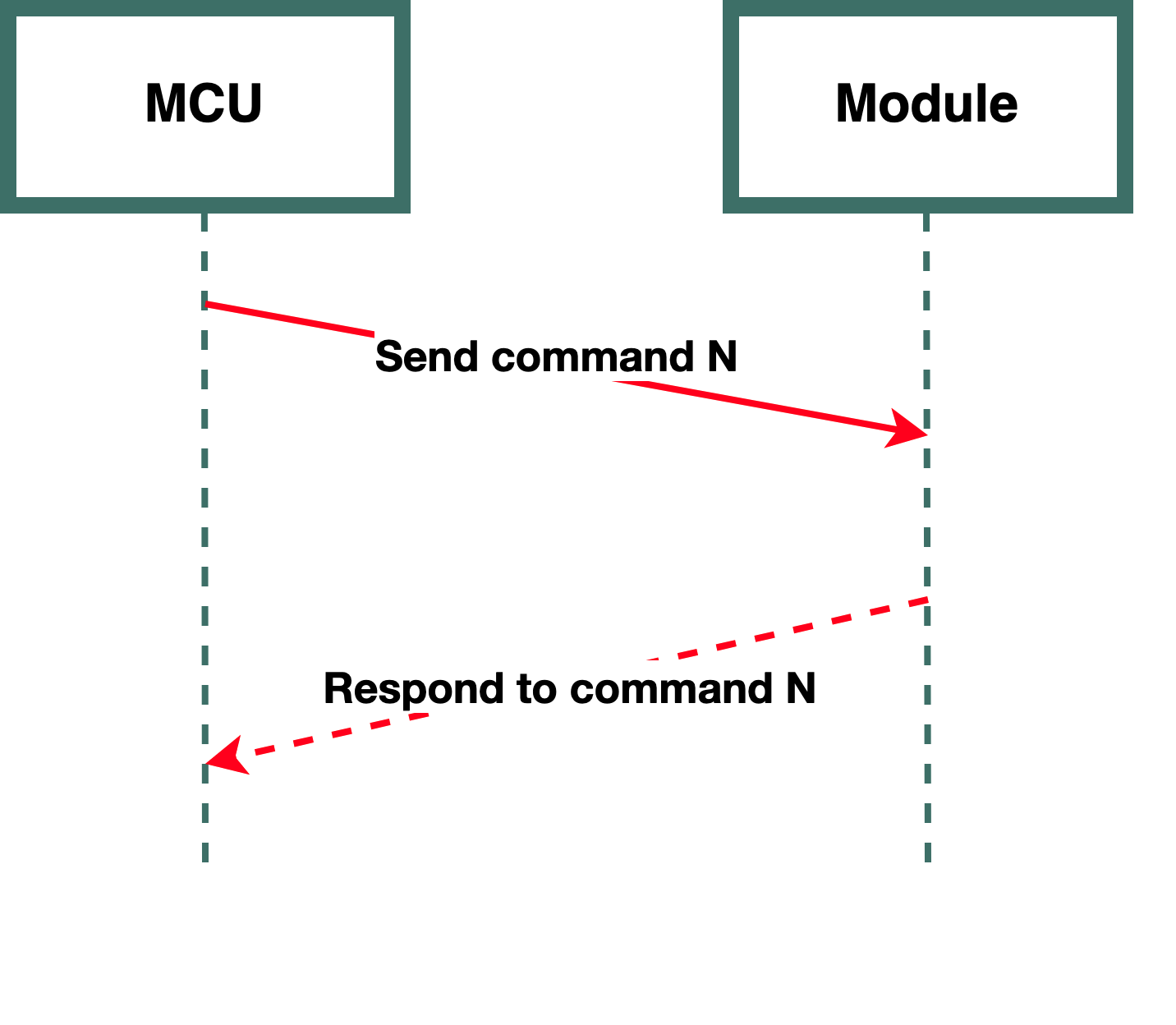
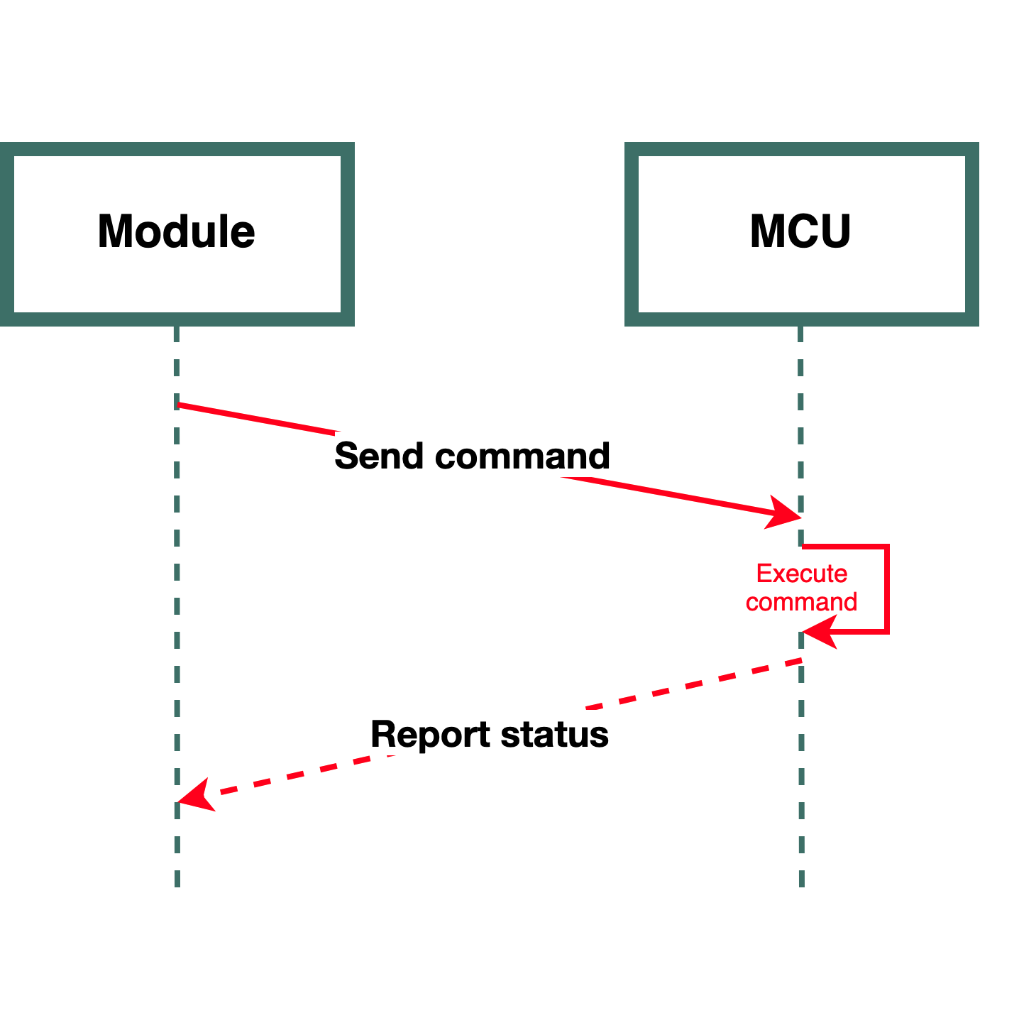
Module sends commands to MCU
The module sends control commands to the MCU in an asynchronous manner.
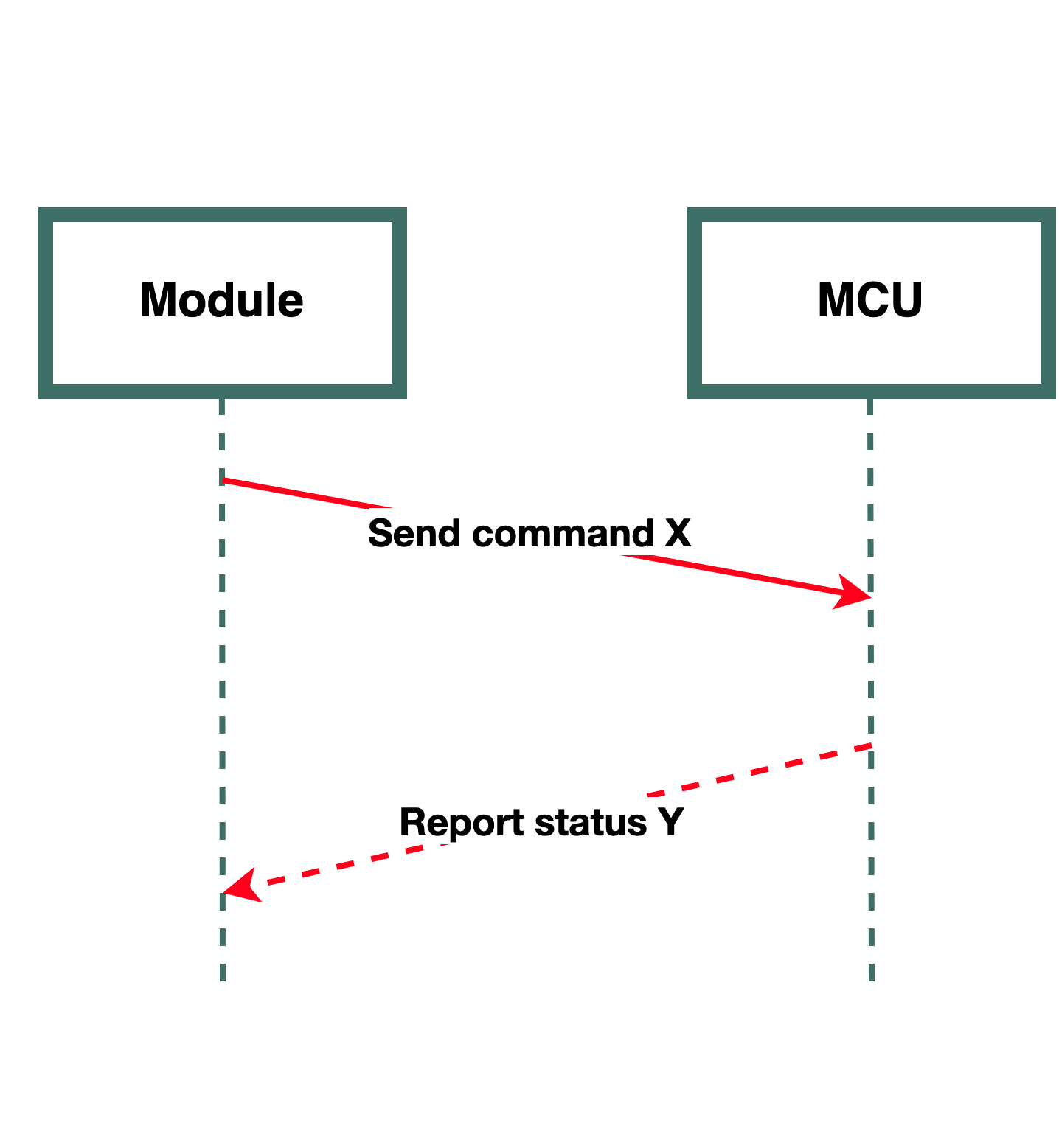
Assume that the module sends a command X and the MCU reports a command Y.
-
The data exchange process:
- The module sends DP commands to the MCU through
0x04. - The MCU acknowledges the receipt of the
0x04packet. - The MCU returns the result of the command execution through
0x05. - Check if the sequence number of the
0x05packet is consistent with the one of the0x04packet.
- The module sends DP commands to the MCU through
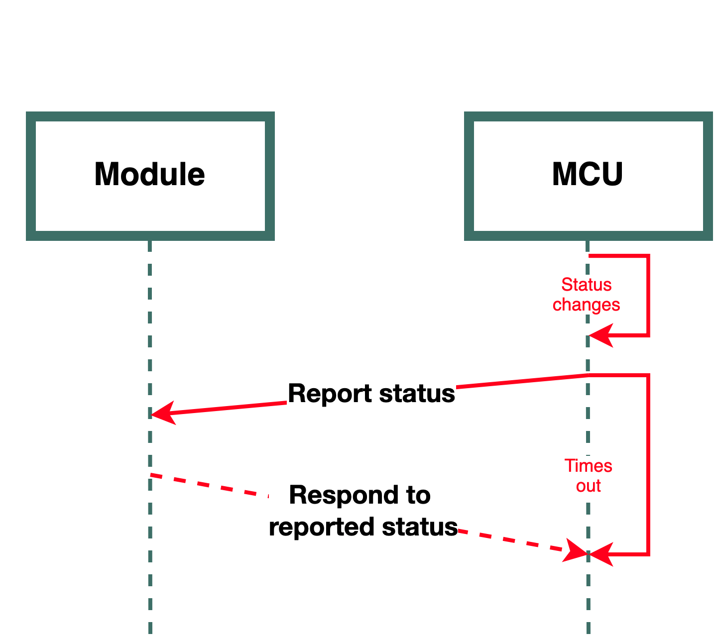
MCU reports status to module
The MCU reports status to the module in an asynchronous manner. The MCU reports status either proactively or passively.
-
Passive reporting: The MCU responds to the status request from the module.
-
Positive reporting: The MCU proactively reports the current status to the module if the device status is changed such as after operations on physical hardware or a restart. After status reporting, if the MCU does not receive a response within the timeout period, or receives a failure result, it will attempt reporting again.
Typical cases
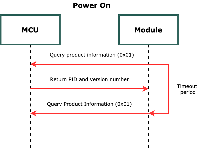
Power on
After the module is powered on, it sends the MCU a request for the PID and version number. If the MCU does not respond within the timeout period, the module tries the request again.
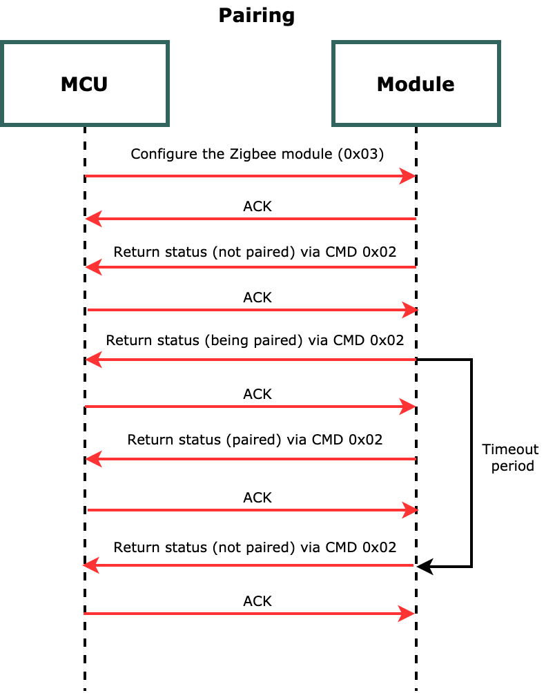
Pairing
After the MCU returns the PID and version number, it can initiate the pairing process by sending the command 0x03 to the module. After the module receives the command, it responds to the MCU with 0x00 (not paired) and then 0x03 (being paired). Within the timeout period, the module returns 0x01 on successful pairing. Otherwise, it returns 0x00 (not paired).
Serial protocol commands
Notify of app-initiated factory reset (0x00)
After users remove a device from the app, the module will send a message to the MCU to restore this device to factory settings. The MCU can determine whether to reset to factory settings.
The module sends the following data.
| Field | Bytes | Description |
|---|---|---|
| Header | 2 | 0x55aa |
| Version | 1 | 0x02 |
| Sequence number | 2 | N |
| Command | 1 | 0x00 |
| Data length | 2 | 0x0001 |
| Data | 1 | 0x01: Factory reset |
| Checksum | 1 | Start from the header, add up all the bytes, and then divide the sum by 256 to get the remainder. |
The MCU returns the following data.
| Field | Bytes | Description |
|---|---|---|
| Header | 2 | 0x55aa |
| Version | 1 | 0x02 |
| Sequence number | 2 | N |
| Command | 1 | 0x00 |
| Data length | 2 | 0x0001 |
| Data | 1 | 0x01: Factory reset succeeds. |
| Checksum | 1 | Start from the header, add up all the bytes, and then divide the sum by 256 to get the remainder. |
Query product information (0x01)
Product information consists of the product ID and the MCU software version number. The module will proactively query the product information after it is reset. If the MCU does not respond to this query or returns the wrong information, the module will send the query again five seconds later.
-
Product ID (PID): a unique identifier assigned to each product created on the Tuya Developer Platform for storing product information in the cloud.
-
MCU software version number: It is expressed in dot-decimal notation,
x.x.x.xis a decimal digit.For OTA update related commands, if the MCU version number is expressed with single-byte characters, the highest version number is
3.3.15due to the byte length limit.
The module sends the following data.
| Field | Bytes | Description |
|---|---|---|
| Header | 2 | 0x55aa |
| Version | 1 | 0x02 |
| Sequence number | 2 | N |
| Command | 1 | 0x01 |
| Data length | 2 | 0x0000 |
| Data | 0 | None |
| Checksum | 1 | Start from the header, add up all the bytes, and then divide the sum by 256 to get the remainder. |
Example
0x55aa 02 N 01 0000 xx
The MCU returns the following data.
| Field | Bytes | Description |
|---|---|---|
| Header | 2 | 0x55aa |
| Version | 1 | 0x02 |
| Sequence number | 2 | N |
| Command | 1 | 0x01 |
| Data length | 2 | N |
| Data | N |
|
| Checksum | 1 | Start from the header, add up all the bytes, and then divide the sum by 256 to get the remainder. |
Example
0x55aa 02 N 01 00 1c 7b2270223a2241497031386b4c49222c2276223a22312e302e30227d xx
Report network status (0x02)
The network status refers to the Zigbee network status, which is independent of the network status of the gateway that the Zigbee module is connected to. After a Zigbee module is successfully paired, it is connected. When the network status of the Zigbee module changes, the module will proactively send its current status to the MCU.
The module sends the following data.
| Field | Bytes | Description |
|---|---|---|
| Header | 2 | 0x55aa |
| Version | 1 | 0x02 |
| Sequence number | 2 | N |
| Command | 1 | 0x02 |
| Data length | 2 | 0x0001 |
| Data | 1 | The network status of the Zigbee module:
|
| Checksum | 1 | Start from the header, add up all the bytes, and then divide the sum by 256 to get the remainder. |
Example
0x55aa 02 N 02 0001 00 xx
The MCU returns the following data.
| Field | Bytes | Description |
|---|---|---|
| Header | 2 | 0x55aa |
| Version | 1 | 0x02 |
| Sequence number | 2 | N |
| Command | 1 | 0x02 |
| Data length | 2 | 0x0000 |
| Data | 0 | None |
| Checksum | 1 | Start from the header, add up all the bytes, and then divide the sum by 256 to get the remainder. |
Example
0x55aa 02 N 02 0000 xx
Configure the Zigbee module (0x03)
The MCU sends the following data.
| Field | Bytes | Description |
|---|---|---|
| Header | 2 | 0x55aa |
| Version | 1 | 0x02 |
| Sequence number | 2 | N |
| Command | 1 | 0x03 |
| Data length | 2 | 0x0001 |
| Data | 1 |
|
| Checksum | 1 | Start from the header, add up all the bytes, and then divide the sum by 256 to get the remainder. |
Example
0x55aa 02 N 03 0001 01 xx
The module returns the following data.
| Field | Bytes | Description |
|---|---|---|
| Header | 2 | 0x55aa |
| Version | 1 | 0x02 |
| Sequence number | 2 | N |
| Command | 1 | 0x03 |
| Data length | 2 | 0x0000 |
| Data | 0 | None |
| Checksum | 1 | Start from the header, add up all the bytes, and then divide the sum by 256 to get the remainder. |
Example
0x55aa 02 N 03 0000 xx
Send commands (0x04)
The Zigbee module sends DP control commands to the MCU.
- All available data types except for the
rawtype are theobjecttypes. - The
objecttypes allow sending several control commands in a single packet. - Module sending commands is an asynchronous operation, corresponding to MCU reporting status.
Frame format:
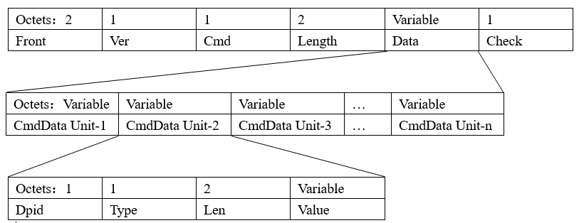
DP data format:
| Field | Bytes | Description |
|---|---|---|
| dpid | 1 | The identifier of a DP (DP ID). |
| type | 1 | It indicates the data type of a DP defined on the Tuya Developer Platform.
|
| len | 2 | The length is the number of bytes of the value. |
| value | 1/2/4/N | Represented in hexadecimal format. Data greater than one byte is transmitted in big-endian format. |
The module sends the following data.
| Field | Bytes | Description |
|---|---|---|
| Header | 2 | 0x55aa |
| Version | 1 | 0x02 |
| Sequence number | 2 | N |
| Command | 1 | 0x04 |
| Data length | 2 | None |
| Data | Depends on data | See DP data format. |
| Checksum | 1 | Start from the header, add up all the bytes, and then divide the sum by 256 to get the remainder. |
Example
0x55aa 02 N 04 0005 03 01 0001 01 xx
03 01 0001 01 indicates that DP 3 of a Boolean type is used for on/off control and 1 means to turn on the device.
Report status (passively) (0x05)
After the MCU receives and correctly executes a command from the module, it reports the changed DP status to the module.
- This is a synchronous command. The module should acknowledge the receipt of the packet on receiving it.
- A packet can contain status data of multiple DPs of
objecttype. - A packet cannot contain both
rawdata andobjectdata.
The MCU sends the following data.
| Field | Bytes | Description |
|---|---|---|
| Header | 2 | 0x55aa |
| Version | 1 | 0x02 |
| Sequence number | 2 | N |
| Command | 1 | 0x05 |
| Data length | 2 | Depends on data |
| Data | Depends on data | See DP data format. |
| Checksum | 1 | Start from the header, add up all the bytes, and then divide the sum by 256 to get the remainder. |
Example
0x55aa 02 N 05 00 08 05 02 0004 0000001e xx
05 02 0004 0000001e indicates that DP 5 of a value type is used for reporting the current humidity, and the current humidity is 30%.
The module returns the following data.
| Field | Bytes | Description |
|---|---|---|
| Header | 2 | 0x55aa |
| Version | 1 | 0x02 |
| Sequence number | 2 | N |
| Command | 1 | 0x05 |
| Data length | 2 | 0x0001 |
| Data | 0 |
|
| Checksum | 1 | Start from the header, add up all the bytes, and then divide the sum by 256 to get the remainder. |
Example
0x55aa 02 N 05 0001 01 xx
Report status (proactively) (0x06)
-
The MCU proactively reports status to the module after it detects status changes in DPs.
- Typically, the MCU reports only the changed DP status.
- If exceptions occur, such as a restart, the MCU reports the status of all DPs.
-
Proactive status reporting is an asynchronous command. When the module receives a response from the Zigbee gateway, it returns the result of reporting to the MCU. If the MCU receives the result of timeout or failure, it should report the status again. Currently, only the command
0x06supports proactive status reporting. Compared to the command0x05,0x06allows the MCU to determine the status of the connection between the module and the gateway based on the response from the module.0x06allows the module to automatically add random delays for the MCU’s response to broadcast messages from the gateway. -
Passive status reporting can contain status data of multiple DPs of
objecttype. -
A packet cannot contain both
rawdata andobjectdata.If you want to sync DP status with the mobile app after successful pairing, we recommend you set a five-second delay for reporting status.
The MCU sends the following data.
| Field | Bytes | Description |
|---|---|---|
| Header | 2 | 0x55aa |
| Version | 1 | 0x02 |
| Sequence number | 2 | N |
| Command | 1 | 0x06 |
| Data length | 2 | Depends on data |
| Data | Depends on data | See DP data format. |
| Checksum | 1 | Start from the header, add up all the bytes, and then divide the sum by 256 to get the remainder. |
Example
0x55aa 02 N 06 08 05 02 0004 0000001e xx
05 02 0004 0000001e indicates that DP 5 of a value type is used for reporting the current humidity, and the current humidity is 30%.
The module returns the following data.
| Field | Bytes | Description |
|---|---|---|
| Header | 2 | 0x55aa |
| Version | 1 | 0x02 |
| Sequence number | 2 | N |
| Command | 1 | 0x06 |
| Data length | 2 | 0x0001 |
| Data | 0 |
|
| Checksum | 1 | Start from the header, add up all the bytes, and then divide the sum by 256 to get the remainder. |
Example
0x55aa 02 N 06 0001 01 xx
Test Zigbee module functionality (0x08)
The Zigbee module scans a designated channel to determine its RSSI value and returns the result and signal strength in percentage. Make sure that the module under test is not paired. The module must be restarted after a test.
The designated channel defaults to channel 11.
The MCU sends the following data.
| Field | Bytes | Description |
|---|---|---|
| Header | 2 | 0x55aa |
| Version | 1 | 0x02 |
| Sequence number | 2 | N |
| Command | 1 | 0x08 |
| Data length | 2 | 0x0001 |
| Data | 1 | The channel value, ranging from 11 to 26. |
| Checksum | 1 | Start from the header, add up all the bytes, and then divide the sum by 256 to get the remainder. |
Example
0x55aa 02 N 08 0001 0b xx indicates that the module is directed to scan channel 11 and get the RSSI value.
The module returns the following data.
| Field | Bytes | Description |
|---|---|---|
| Header | 2 | 0x55aa |
| Version | 1 | 0x02 |
| Sequence number | 2 | N |
| Command | 1 | 0x08 |
| Data length | 2 | 0x0002 |
| Data | 2 |
|
| Checksum | 1 | Start from the header, add up all the bytes, and then divide the sum by 256 to get the remainder. |
Example
0x55aa 02 N 08 0002 01 64 xx
The invalid channel defaults to channel 11.
Scene switch
For scene switches, the MCU only needs to tell the Zigbee module the number of keys and which keys are pressed.
Query configuration of keys (0x09)
The module will query the configuration of keys after a restart.
- Up to 10 keys are configurable, meaning at most 10 scenes can be created.
- This command applies to scene control panels only.
- Select the scene ID group and scene number (1–10) when you define DPs on the platform.
- The scene number must be in ascending order, starting with 1.
The module sends the following data.
| Field | Bytes | Description |
|---|---|---|
| Header | 2 | 0x55aa |
| Version | 1 | 0x02 |
| Sequence number | 2 | N |
| Command | 1 | 0x09 |
| Data length | 2 | 0x0000 |
| Data | 0 | None |
| Checksum | 1 | Start from the header, add up all the bytes, and then divide the sum by 256 to get the remainder. |
Example
0x55aa 02 N 09 0000 xx
The MCU returns the following data.
| Field | Bytes | Description |
|---|---|---|
| Header | 2 | 0x55aa |
| Version | 1 | 0x02 |
| Sequence number | 2 | N |
| Command | 1 | 0x09 |
| Data length | 2 | 0x0001 |
| Data | 2 | The total number of keys. |
| Checksum | 1 | Start from the header, add up all the bytes, and then divide the sum by 256 to get the remainder. |
Example
0x55aa 02 N 09 0001 02 xx
Wake up scenes (0x0a)
This command is used to trigger a scene. The module can return either success or failure after receiving a scene execution command.
- Success: The specified key has been associated with a scene on the app and the scene execution is completed.
- Failure: The specified key has not been associated with a scene on the app and the scene cannot be run.
After a key is pressed, the scene control panel will send a key value to the gateway for cloud-based scenes. When the MCU reports the status of a key, the module will send a packet to the gateway. If only the cloud-based scene is configured, the reporting is considered a success no matter what results are returned.
Differences between cloud-based scenes and local scenes
- Local scene: refers to scenes that are configured following the standard Zigbee protocol.
The scene data stored on the Zigbee hardware is the specified property values, so certain features are not supported. These unsupported features must be implemented by the cloud-based scenes.
- Cloud-based scenes: refers to scenes that are implemented through scene data processing on the cloud.
This command only supports local scenes currently. If devices of other protocols such as Wi-Fi and Bluetooth are included, cloud-based scenes should be used.
The MCU sends the following data.
| Field | Bytes | Description |
|---|---|---|
| Header | 2 | 0x55aa |
| Version | 1 | 0x02 |
| Sequence number | 2 | N |
| Command | 1 | 0x0A |
| Data length | 2 | 0x0001 |
| Data | Depends on data | The key ID. For example, if the total number of keys is four, the data is |
| Checksum | 1 | Start from the header, add up all the bytes, and then divide the sum by 256 to get the remainder. |
Example
0x55aa 02 N 0A 0001 01 xx indicates that the MCU directs the module to execute the scene associated with key 1.
The module returns the following data.
| Field | Bytes | Description |
|---|---|---|
| Header | 2 | 0x55aa |
| Version | 1 | 0x02 |
| Sequence number | 2 | N |
| Command | 1 | 0x0A |
| Data length | 2 | 0x0001 |
| Data | 1 |
|
| Checksum | 1 | Start from the header, add up all the bytes, and then divide the sum by 256 to get the remainder. |
Example
0x55aa 02 N 0A 0001 01 xx
MCU firmware update via OTA
The OTA firmware update process:
- The cloud initiates an OTA update.
- The MCU responds to the update request.
- The MCU requests downloading the updates. A packet is up to 50 bytes.
- The module forwards the request to the gateway.
- The gateway returns the start offset and packet size.
To ensure a reliable update process, you need to implement a timeout mechanism for the updates download request. If the MCU does not receive a response within a timeout period, it sends the request again.
The timeout period can be three to five seconds, and the MCU can retry five times. With this mechanism, if the MCU does not receive a response within three to five seconds for five times and above, it will cancel the update.
Request MCU firmware version (0x0b)
If you want to update the MCU firmware using OTA, this command must be implemented. The gateway can query the MCU firmware version or the MCU proactively reports it.
- The gateway queries the MCU firmware version when:
- The device is successfully paired.
- An exception occurs during an update process.
- The MCU proactively reports its firmware version when:
- (Required) The device is successfully paired.
- An update is completed.
The module sends the following data.
| Field | Bytes | Description |
|---|---|---|
| Header | 2 | 0x55aa |
| Version | 1 | 0x02 |
| Sequence number (seq) | 2 | Generated by the module |
| Command | 1 | 0x0B |
| Data length | 2 | 0x0000 |
| Data | 0 | None |
| Checksum | 1 | Start from the header, add up all the bytes, and then divide the sum by 256 to get the remainder. |
Example
0x55 AA 02 00 f0 0B 00 00 XX
The MCU returns the following data.
| Field | Bytes | Description |
|---|---|---|
| Header | 2 | 0x55aa |
| Version | 1 | 0x02 |
| Sequence number (seq) | 2 | Sent from the MCU |
| Command | 1 | 0x0B |
| Data length | 2 | 0x0001 |
| Data | 1 | The current version number. For example, |
| Checksum | 1 | Start from the header, add up all the bytes, and then divide the sum by 256 to get the remainder. |
Example
55 AA 02 00 39 0B 00 01 40 XX
For OTA update related commands, if the MCU version number is expressed with single-byte characters, the highest version number is 3.3.15 due to the byte length limit.
Notify of an available OTA update (0x0c)
The module sends the following data.
| Field | Bytes | Description |
|---|---|---|
| Header | 2 | 0x55aa |
| Version | 1 | 0x02 |
| Sequence number (seq) | 2 | Generated by the module |
| Command | 1 | 0x0C |
| Data length | 2 | 0x0011 |
| Data | 8 | The PID, from Data[0] to Data[7] |
| Data | 1 | The current version number. For example, |
| Data | 4 | The firmware size. For Zigbee device connection to the latest Tuya-enabled wireless gateway and wired gateway, the maximum firmware size is 512 KB and 1 MB respectively. |
| Data | 4 | Firmware checksum: The checksum of the entire firmware from the first byte. |
| Checksum | 1 | Start from the header, add up all the bytes, and then divide the sum by 256 to get the remainder. |
Example
0x55 AA 02 00 1C 0C 00 0F 30 31 32 33 34 35 36 37 40 00 01 00 00 30 31 32 33 XX
The MCU returns the following data.
| Field | Bytes | Description |
|---|---|---|
| Header | 2 | 0x55aa |
| Version | 1 | 0x02 |
| Sequence number (seq) | 2 | The sequence number sent from the module. |
| Command | 1 | 0x0C |
| Data length | 2 | 0x0001 |
| Data | 1 |
|
| Checksum | 1 | Start from the header, add up all the bytes, and then divide the sum by 256 to get the remainder. |
Example
0x55 AA 02 00 1C 0C 00 01 00 XX
Request downloading the update file over OTA (0x0d)
The MCU sends the following data.
| Field | Bytes | Description |
|---|---|---|
| Header | 2 | 0x55aa |
| Version | 1 | 0x02 |
| Sequence number (seq) | 2 | 0x0000 |
| Command | 1 | 0x0D |
| Data length | 2 | 0x000E |
| Data | 8 | The PID. |
| Data | 1 | The current version number. For example, |
| Data | 4 | The start offset |
| Data | 1 | The packet size, up to 50 bytes. |
| Checksum | 1 | Start from the header, add up all the bytes, and then divide the sum by 256 to get the remainder. |
Example
0x55 AA 02 00 00 0D 00 0E 30 31 32 33 34 35 36 37 40 00 00 00 01 32 XX
The module returns the following data.
| Field | Bytes | Description |
|---|---|---|
| Header | 2 | 0x55aa |
| Version | 1 | 0x02 |
| Sequence number (seq) | 2 | 0x0000 |
| Command | 1 | 0x0D |
| Data length | 2 | 0x0006+N |
| Data | 1 |
|
| Data | 8 | The PID. |
| Data | 1 | The current version number. For example, |
| Data | 4 | The start offset |
| Data | N | Data |
| Checksum | 1 | Start from the header, add up all the bytes, and then divide the sum by 256 to get the remainder. |
Example
55 AA 02 00 39 0D XXXX 00 30 31 32 33 34 35 36 37 40 00 00 00 01 ... XX
Return the update result (0x0e)
The MCU sends the following data.
| Field | Bytes | Description |
|---|---|---|
| Header | 2 | 0x55aa |
| Version | 1 | 0x02 |
| Sequence number (seq) | 2 | The sequence number sent from the MCU. |
| Command | 1 | 0x0E |
| Data length | 2 | 0x000A |
| Data | 1 |
|
| Data | 8 | The PID. |
| Data | 1 | The current version number. For example, |
| Checksum | 1 | Start from the header, add up all the bytes, and then divide the sum by 256 to get the remainder. |
Example
0x55 AA 03 00 f0 0E 00 0A 00 30 31 32 33 34 35 36 37 40 26
The module returns the following data.
| Field | Bytes | Description |
|---|---|---|
| Header | 2 | 0x55aa |
| Version | 1 | 0x02 |
| Sequence number (seq) | 2 | The sequence number sent from the MCU. |
| Command | 1 | 0x0E |
| Data length | 2 | 0x0001 |
| Data | 1 |
|
| Checksum | 1 | Start from the header, add up all the bytes, and then divide the sum by 256 to get the remainder. |
Example
0x55 AA 02 00 1C 0E 00 01 00 XX
Query Zigbee network status (0x20)
The MCU can query the current network status of the Zigbee module.
Before you use this command, verify if the firmware in use supports it.
The MCU sends the following data.
| Field | Bytes | Description |
|---|---|---|
| Header | 2 | 0x55aa |
| Version | 1 | 0x02 |
| Sequence number | 2 | N |
| Command | 1 | 0x20 |
| Data length | 2 | 0x0000 |
| Checksum | 1 | Start from the header, add up all the bytes, and then divide the sum by 256 to get the remainder. |
Example
0x55aa 02 N 20 0000 xx
The module returns the following data.
| Field | Bytes | Description |
|---|---|---|
| Header | 2 | 0x55aa |
| Version | 1 | 0x02 |
| Sequence number | 2 | N |
| Command | 1 | 0x20 |
| Data length | 2 | 0x0001 |
| Data | 1 | The network status of the Zigbee module:
|
| Checksum | 1 | Start from the header, add up all the bytes, and then divide the sum by 256 to get the remainder. |
Example
0x55aa 02 N 20 0001 xx xx
Sync clock time (0x24)
The MCU syncs its clock time with the network time on the gateway.
The MCU sends the following data.
| Field | Bytes | Description |
|---|---|---|
| Header | 2 | 0x55aa |
| Version | 1 | 0x02 |
| Sequence number | 2 | N |
| Command | 1 | 0x24 |
| Data length | 2 | 0x0000 |
| Data | 0 | None |
| Checksum | 1 | Start from the header, add up all the bytes, and then divide the sum by 256 to get the remainder. |
The module returns the following data.
| Field | Bytes | Description |
|---|---|---|
| Header | 2 | 0x55aa |
| Version | 1 | 0x02 |
| Sequence number | 2 | N |
| Command | 1 | 0x024 |
| Data length | 2 | 0x0008 |
| Data | 8 | The time value is 8 bytes. It takes the format of 4-byte Unix timestamp + 4-byte local timestamp. |
| Checksum | 1 | Start from the header, add up all the bytes, and then divide the sum by 256 to get the remainder. |
- The Unix timestamp tracks time as a running count of seconds. The count begins at the Unix epoch on January 1st, 1970 at 00:00:00, so a Unix timestamp is the total seconds between any given date and the Unix epoch.
- The local timestamp is calculated by adding the time zone offset and DST to the Unix timestamp.
MCU requests gateway connection status (0x25)
After receiving the request from the MCU, the Zigbee module sends the request to the Zigbee gateway. The Zigbee module sends the MCU the connection status received from the Zigbee gateway. If the Zigbee gateway fails to respond after three seconds, the request timed out.
The MCU sends the following data.
| Field | Bytes | Description |
|---|---|---|
| Header | 2 | 0x55aa |
| Version | 1 | 0x02 |
| Sequence number | 2 | N |
| Command | 1 | 0x25 |
| Data length | 2 | 0x0000 |
| Data | 0 | None |
| Checksum | 1 | Start from the header, add up all the bytes, and then divide the sum by 256 to get the remainder. |
Example
55 aa 02 N 25 00 00 xx
The module returns the following data.
| Field | Bytes | Description |
|---|---|---|
| Header | 2 | 0x55aa |
| Version | 1 | 0x02 |
| Sequence number | 2 | N |
| Command | 1 | 0x025 |
| Data length | 2 | 0x0001 |
| Data | 1 |
|
| Checksum | 1 | Start from the header, add up all the bytes, and then divide the sum by 256 to get the remainder. |
Example
55 aa 02 N 25 00 01 01 xx
Configure Zigbee network policy (0x26)
After responding to a product information query, the MCU sends this command to set the Zigbee network policy after a millisecond delay.
- The module will be restarted after successfully executing the received command.
- The mains-powered devices can only set the transmitter power currently.
-
Heartbeat interval
The heartbeat mechanism is used to monitor the health of the network connection between Zigbee devices and gateways. The heartbeat interval defaults to
150 + random (30)seconds for electrical devices, and defaults to four hours for low power devices. If the gateway does not receive a heartbeat packet within 12 hours, it will declare that a device is offline. You can only modify the heartbeat interval for low power devices. -
Timeout period
After the MCU sends a pairing command, the module will attempt to join a network and tell the MCU that it has entered the pairing mode. If the module fails to join a network within a specified time period due to issues such as poor network conditions, the pairing times out. In this case, the module returns the unpaired state to the MCU.
-
Polling
The polling interval is used to periodically wake up the low power devices in the network. After waking up, the module will send a data request to its parent node to check for cached data. If there is cached data, the parent node will send it to the module.
-
Polling settings
- For devices that require near-real-time status updates such as smart switches, you can set the polling interval to 250 milliseconds.
- For devices that are not real-time dependent, the MCU can report data when the status of specific DP changes or on a regular basis. In this case, polling can be turned off except when the MCU reports data. With polling turned off, the module cannot receive commands from the gateway.
-
Polling settings after power on
You can start quick polling after the module is powered on to let the gateway send configuration data to the module. The polling period is configurable and defaults to 30 seconds. If polling is intended to be turned off later but the module has to receive configuration data from the gateway, you can extend the time window for polling. -
Turn off polling
The gateway will cache data received from the cloud. To check for cached data, the module will carry a data request when it reports data to the gateway.
The polling interval correlates with power consumption. The shorter the interval, the higher the power consumption. The minimum polling interval is 200 milliseconds. A maximum of five seconds is recommended. If the interval is set to 0, polling is turned off.
-
-
Rejoin
Zigbee supports rejoining, where an end device can attempt several times to join the lost network again if it is disconnected from its parent node.
Rejoining is different from pairing so the gateway does not need to turn on the pairing mode.
The rejoining process:
- The module sends a data request.
- The parent node responds.
- If there is cached data, the parent node will send it to the module.
- If there is no cached data, the parent node only sends an acknowledgment packet.
If the module fails to receive an acknowledgment due to issues such as poor network conditions, the polling is considered failed. If the amount of failed attempts exceeds a threshold, the module’s connection to its parent node is considered lost, and rejoining will be triggered.
If the module receives an acknowledgment during the accumulation of failed attempts, the counter will be cleared to zero.
-
Trigger rejoining
Two independent methods are available to trigger rejoining.- The application sends data to trigger rejoining.
- Scheduled triggers: If the module is offline, it will trigger rejoining periodically until joining the lost network again.
Successful rejoining only means the module resumes its communication with the parent node. The success of data transmission depends on if the parent node can route data packets to the gateway. These two rejoining methods are both configurable.
-
Rejoining interval
Specify a time interval to trigger rejoining periodically. For devices that are real-time dependent or feature low power consumption, you can set an interval between three to five seconds. If polling is triggered by data reporting, such as for sensors, you can set a longer interval, such as one hour. -
Rejoining attempts
Specify the amount of rejoining attempts. For devices that are real-time dependent or have a shorter rejoining interval, the rejoining attempts can be decreased, such as once or twice. For devices that have a longer rejoining interval, the rejoining attempts can be increased, such as three or four times.
If you specify an invalid value, this parameter will not take effect.
The MCU sends the following data.
| Field | Bytes | Description |
|---|---|---|
| Header | 2 | 0x55aa |
| Version | 1 | 0x02 |
| Sequence number | 2 | N |
| Command | 1 | 0x26 |
| Data length | 2 | 0x0e |
| Data | 2 | The heartbeat interval. Only low power devices support configurable heartbeat intervals. The heartbeat interval for low power devices defaults to four hours. The valid value ranges from 10 to 18,000 seconds.
|
| 2 | The timeout period. It defaults to 180 seconds. The valid value ranges from 30 to 600 seconds.
|
|
| 2 | The rejoining interval. It defaults to 180 seconds, meaning the module will try rejoining every 180 seconds if it lost connection with its parent node. The valid value ranges from 3 to 3,600 seconds.
|
|
| 2 | The polling interval. It defaults to 5,000 milliseconds. The valid value ranges from 200 to 10,000 milliseconds. The module will wake up based on the polling interval to check for cached data on the parent node. For sensors that report data only, you can set the polling interval to 0.
|
|
| 2 | The duration of quick polling after the module is powered on. The valid value ranges from 10 to 3,000 seconds. The quick polling runs 250 milliseconds. After that, polling runs at the normal interval of 30 seconds.
|
|
| 1 | The amount of failed attempts. The valid value ranges from 3 to 40. If rejoining trigger is set, when the threshold is reached, the module will try rejoining the lost network.
|
|
| 1 | Specify whether to enable the application to trigger rejoining attempts.
|
|
| 1 | Rejoining attempts. It defaults to 1. The value ranges from 1 to 10.
|
|
| 1 | The transmitter power. It defaults to 11. The value ranges from 3 to 19 dB. For Telink and Phyplus, the transmitter power ranges from 3 to 11 dB.
|
|
| Checksum | 1 | Start from the header, add up all the bytes, and then divide the sum by 256 to get the remainder. |
The module returns the following data.
| Field | Bytes | Description |
|---|---|---|
| Header | 2 | 0x55aa |
| Version | 1 | 0x02 |
| Sequence number | 2 | N |
| Command | 1 | 0x026 |
| Data length | 2 | 0x0001 |
| Data | 1 |
|
| Checksum | 1 | Start from the header, add up all the bytes, and then divide the sum by 256 to get the remainder. |
Broadcast messages (0x27)
This command is used for the MCU to broadcast messages across the network.
The broadcast interval must be specified. The value depends on the network scale.
All devices in the network can receive the broadcast packet. For low power devices, cyclic wake-up must be set. The wake-up interval must be shorter than the broadcast interval. Otherwise, the old packet will be overwritten.
The MCU sends the following data.
| Field | Bytes | Description |
|---|---|---|
| Header | 2 | 0x55aa |
| Version | 1 | 0x02 |
| Sequence number | 2 | N |
| Command | 1 | 0x27 |
| Data length | 2 | N |
| Data | Depends on data | See DP data format. |
| Checksum | 1 | Start from the header, add up all the bytes, and then divide the sum by 256 to get the remainder. |
The module returns the following data.
| Field | Bytes | Description |
|---|---|---|
| Header | 2 | 0x55aa |
| Version | 1 | 0x02 |
| Sequence number | 2 | N |
| Command | 1 | 0x027 |
| Data length | 2 | 0x0001 |
| Data | 1 | 0x00: failure 0x01: success |
| Checksum | 1 | Start from the header, add up all the bytes, and then divide the sum by 256 to get the remainder. |
Gateway reads DP data (0x28)
You can use this command to initiate status reporting. This enables the MCU to report the current status of some or all DPs to sync with the mobile app.
If the data field is empty, it means that status of all DPs should be reported. To report the status of some DPs, the MCU can include the specified DP ID in the payload. For example, if the payload contains 0x01 and 0x02, it means the MCU reports DP1 and DP2. Up to 10 DPs can be reported in one packet. If the data length exceeds 64 bytes, data must be transmitted in different packets. The data reporting operation is performed through 0x06.
You can determine which DPs are reported based on your product features.
You can also use this command to sync status with the app after a device resumes its network connection, but use it with caution. If the status of DPs that are associated with scene automation is reported, the associated scenes might be triggered.
The module sends the following data.
| Field | Bytes | Description |
|---|---|---|
| Header | 2 | 0x55aa |
| Version | 1 | 0x02 |
| Sequence number | 2 | N |
| Command | 1 | 0x28 |
| Data length | 2 | N |
| Data | N | The payload contains specific DPs or is empty. |
| Checksum | 1 | Start from the header, add up all the bytes, and then divide the sum by 256 to get the remainder. |
The MCU returns the following data.
| Field | Bytes | Description |
|---|---|---|
| Header | 2 | 0x55aa |
| Version | 1 | 0x02 |
| Sequence number | 2 | N |
| Command | 1 | 0x028 |
| Data length | 2 | 0x0001 |
| Data | 1 | 0x00: failure 0x01: success |
| Checksum | 1 | Start from the header, add up all the bytes, and then divide the sum by 256 to get the remainder. |
Initiate a beacon-based RF test (0x29)
Unpaired devices in the proximity of a beacon dongle will enter the test mode after power on. In this case, the module will notify the MCU to start the test.
This command applies to the MCU that cannot initiate a test. For example, some lighting fixtures do not have physical buttons to trigger test mode. This command can help in this case. After receiving a beacon signal, the module will notify the MCU to start a test immediately. The module sends the packet at the baud 9600. If receiving no response, it will try the baud 115200. If there is still no response, the module will resend the packet twice with baud 9600 at an interval of 100 milliseconds. Then, it repeats this process with baud 115200. If the notification failed, shut down and restart the device in an environment without beacon signals. In this process, the module does not respond to any other commands from the MCU.
The module sends the following data.
| Field | Bytes | Description |
|---|---|---|
| Header | 2 | 0x55aa |
| Version | 1 | 0x02 |
| Sequence number | 2 | N |
| Command | 1 | 0x29 |
| Data length | 2 | 1 |
| Data | 1 | 00 |
| Checksum | 1 | Start from the header, add up all the bytes, and then divide the sum by 256 to get the remainder. |
The MCU returns the following data.
| Field | Bytes | Description |
|---|---|---|
| Header | 2 | 0x55aa |
| Version | 1 | 0x02 |
| Sequence number | 2 | N |
| Command | 1 | 0x029 |
| Data length | 2 | 0x0001 |
| Data | 1 |
|
| Checksum | 1 | Start from the header, add up all the bytes, and then divide the sum by 256 to get the remainder. |
Send commands as multicast (0x2a)
In a Zigbee network, control commands can be sent as unicast or multicast. The MCU can distinguish these two messaging types by command and therefore reports data according to the specified policy. To use this command, the MCU should include the parameter g in the response to the production information query (0x01) to indicate whether group control is available.
You can set the policies for data reporting after multicast commands are run. For example, devices do not report the current status until the gateway sends a status request. Or add random delays for reporting status to avoid Zigbee network congestion.
- The message payload that the module sends to the MCU uses the same format as the command
0x04. - The MCU reports status using the command
0x05or0x06, with the reporting policies defined by you.
The module sends the following data.
| Field | Bytes | Description |
|---|---|---|
| Header | 2 | 0x55aa |
| Version | 1 | 0x02 |
| Sequence number (seq) | 2 | Generated by the module |
| Command | 1 | 0x2A |
| Data length | 2 | N |
| Data | Depends on data | See DP data format. |
| Checksum | 1 | Start from the header, add up all the bytes, and then divide the sum by 256 to get the remainder. |
Example
55 AA 02 00 01 2A 00 04 01 01 00 01 01 34
The MCU returns the following data.
| Field | Bytes | Description |
|---|---|---|
| Header | 2 | 0x55aa |
| Version | 1 | 0x02 |
| Sequence number | 2 | N |
| Command | 1 | 0x2A |
| Data length | 2 | 0x0000 |
| Data | 0 | None |
| Checksum | 1 | Start from the header, add up all the bytes, and then divide the sum by 256 to get the remainder. |
Example
55 aa 02 00 01 2A 00 00 2C
Set the waiting time after waking up MCU (0x2b)
For low-power devices, the module should wake up the MCU before sending serial data. You can set the time that the module should wait after it wakes up the MCU.
The MCU sends the following data.
| Field | Bytes | Description |
|---|---|---|
| Header | 2 | 0x55aa |
| Version | 1 | 0x02 |
| Sequence number (seq) | 2 | The sequence number sent from the MCU. |
| Command | 1 | 0x2B |
| Data length | 2 | 0x0002 |
| Data | 2 | The amount of waiting time, in milliseconds. The value must be 3 to 300, with a default value of 5 (represented by 0xFFFE). |
| Checksum | 1 | Start from the header, add up all the bytes, and then divide the sum by 256 to get the remainder. |
Example
55 AA 02 00 01 2B 00 02 00 64 93
The module returns the following data.
| Field | Bytes | Description |
|---|---|---|
| Header | 2 | 0x55aa |
| Version | 1 | 0x02 |
| Sequence number (seq) | 2 | The sequence number sent from the MCU. |
| Command | 1 | 0x2B |
| Data length | 2 | 0x0001 |
| Data | 1 |
|
| Checksum | 1 | Start from the header, add up all the bytes, and then divide the sum by 256 to get the remainder. |
Example
55 AA 02 00 01 2B 00 01 01 2F
To use 0x41, 0x42, 0x43, you must
- Select the DP with the identifier of
scene_switch. - Select a panel that supports eight groups. For wireless switch products, the eight-group feature is not generally available. You can submit a service ticket to request access to this feature for debugging.
Send kid, gid, and sid (0x41)
For control panels with eight-group supported and scene control modules built in (0x41, 0x42, 0x43 enabled), after it is paired, the module will receive the information about groups and keys from the cloud and transmit it to the MCU.
kid: The ID of a key.gid: The ID of a Zigbee group.sid: The ID of a Zigbee scene.
- This command only applies to devices with the scene control module adopted and the eight-group feature supported.
- If the value of
sidis0, it means no scene ID exists. - The MCU should take care of storing the received
kid,gid, andsid.
The module sends the following data.
| Field | Bytes | Description |
|---|---|---|
| Header | 2 | 0x55aa |
| Version | 1 | 0x02 |
| Sequence number (seq) | 2 | Generated by the module |
| Command | 1 | 0x41 |
| Data length | 2 | 0x0004 |
| Data | 1 | kid (1-8) |
| Data | 2 | gid |
| Data | 1 | sid |
| Checksum | 1 | Start from the header, add up all the bytes, and then divide the sum by 256 to get the remainder. |
Example
55 AA 02 00 01 41 00 04 01 2A 08 00 7A
The MCU returns the following data.
| Field | Bytes | Description |
|---|---|---|
| Header | 2 | 0x55aa |
| Version | 1 | 0x02 |
| Sequence number | 2 | N |
| Command | 1 | 0x41 |
| Data length | 2 | 0x0001 |
| Data | 1 |
|
| Checksum | 1 | Start from the header, add up all the bytes, and then divide the sum by 256 to get the remainder. |
Example
55 aa 02 00 01 41 00 01 01 45
Multicast with standard commands (0x42)
The MCU sends multicast messages to a group of devices in the Zigbee network by using the standard commands.
The multicast message is only used to instruct a group of devices to perform the specified action. Devices need to report status separately.
The MCU sends the following data.
| Field | Bytes | Description |
|---|---|---|
| Header | 2 | 0x55aa |
| Version | 1 | 0x02 |
| Sequence number (seq) | 2 | The sequence number sent from the MCU. |
| Command | 1 | 0x42 |
| Data length | 2 | n byte(s) |
| Data | n | gid + standard command (see the following table for the format) |
| Checksum | 1 | Start from the header, add up all the bytes, and then divide the sum by 256 to get the remainder. |
Example
55 AA 02 00 01 42 00 05 2A 08 00 06 01 82
The module returns the following data.
| Field | Bytes | Description |
|---|---|---|
| Header | 2 | 0x55aa |
| Version | 1 | 0x02 |
| Sequence number (seq) | 2 | The sequence number sent from the MCU. |
| Command | 1 | 0x42 |
| Data length | 2 | 0x0001 |
| Data | 1 |
|
| Checksum | 1 | Start from the header, add up all the bytes, and then divide the sum by 256 to get the remainder. |
Example
55 AA 02 00 01 42 00 01 01 46
The following clusters and commands are supported:
On/Off Cluster
- On
- Off
- Toggle
Level Control Cluster
- Move to Level
- Move
- Step
- Stop
- Move to Level (with On/Off)
- Move (with On/Off)
- Step (with On/Off)
- Stop
Color Control Cluster
- Move to Hue
- Move Hue
- Step Hue
- Move to Saturation
- Move Saturation
- Step Saturation
- Move to Hue and Saturation
- Move to Color
- Move Color
- Step Color
- Move to Color Temperature
- Move Color Temperature
- Step Color Temperature
- Stop Move Step
Window Covering Cluster
- Up/Open
- Down/Close
- Stop
- Go To Lift Value
- Go to Lift Percentage
- Go to Tilt Value
- Go to Tilt Value
Scenes Cluster
- Recall Scene
Format of standard commands:
| Cluster ID | Command ID | ZCL payload | Description |
|---|---|---|---|
| 0x0006 | 0x00 | None | Off |
| 0x0006 | 0x01 | None | On |
| 0x0006 | 0x02 | None | Toggle |
| 0x0008 | 0x00 | 0x64 00 32 | For the Move to Level command, if the value of Level is 0x64, the transition time is 0x0032. |
| … | … | … | … |
Multicast with private commands (0x43)
The MCU uses the private commands to multicast a message to all devices in a specified group.
- You should know the format and content of the DPs on the device to be controlled.
- The multicast message is only used to instruct a group of devices to perform the specified action. Devices need to report status separately.
The MCU sends the following data.
| Field | Bytes | Description |
|---|---|---|
| Header | 2 | 0x55aa |
| Version | 1 | 0x02 |
| Sequence number (seq) | 2 | The sequence number sent from the MCU. |
| Command | 1 | 0x43 |
| Data length | 2 | n byte(s) |
| Data | n | gid + DP format (see the following table for the format) |
| Checksum | 1 | Start from the header, add up all the bytes, and then divide the sum by 256 to get the remainder. |
Example
55 AA 02 00 01 43 00 07 2A 08 01 01 00 01 01 82
The module returns the following data.
| Field | Bytes | Description |
|---|---|---|
| Header | 2 | 0x55aa |
| Version | 1 | 0x02 |
| Sequence number (seq) | 2 | The sequence number sent from the MCU. |
| Command | 1 | 0x43 |
| Data length | 2 | 0x0001 |
| Data | 1 |
|
| Checksum | 1 | Start from the header, add up all the bytes, and then divide the sum by 256 to get the remainder. |
Example
55 AA 02 00 01 43 00 01 01 47
DP format:
dpid (1 byte) + type (1 byte) + len (2 bytes) + value (n byte)
Type:
| Number | Type |
|---|---|
| 0x00 | Raw |
| 0x01 | Boolean |
| 0x02 | value |
| 0x03 | string |
| 0x04 | Enum |
| 0x05 | Bitmap |
Protocol version
| Changes | Date | Description |
|---|---|---|
| Optimization | November 14, 2022 | Optimized layout and description. |
| Adding | September 2, 2022 | 1. Added the command used by the MCU to request the network status of the gateway. |
| Adding | August 17, 2022 | 1. Added the commands 0x2A, 0x2B, 0x41, 0x42, and 0x43. 2. Added the option to set the transmission power of mains-powered devices. 3. Added the optional field g in the product information. |
| Optimization | March 22, 2022 | Modified the description of the auto-baud detection. |
| Optimization | December 14, 2021 | 1. Added remote factory reset notification, Zigbee network policy configuration, MCU broadcasting messages, and reading DP data. |
| Optimization | November 18, 2020 | 1. Specified that voltage level or pulse is used to wake up the module and the MCU. 2. Specified that the rejoining duration refers to the accumulation of failed attempts. |
| Optimization | August 1, 2020 | 1. Added fields to MCU type query. 2. Added fields to network policy configuration. |
| Optimization | July 15, 2020 | 1. Specified the range of sequence numbers. 2. Modified the data length to 62 bytes. 3. Specified that the channel for testing defaults to channel 11. 4. Added protocol descriptions. |
| Optimization | February 4, 2020 | Added logic for indicating pairing status. |
| Amendment | October 29, 2018 | 1. Added reliable data transmission. 2. Added wake-up mechanism for low power devices. |
| Amendment | July 31, 2018 | 1. Added protocols for scene switches. |
| Amendment | July 2, 2018 | 1. Added passive data reporting and retransmission mechanism. 2. Added hardware handshaking. |
| Amendment | June 28, 2018 | 1. Modified the timeout period. 2. Modified the passive reporting method. 3. Modified the module configuration method. |
| Creation | June 23, 2018 | The initial version. |
Is this page helpful?
YesFeedbackIs this page helpful?
YesFeedback


