UART Protocol for Zigbee Three-level Architecture
Overview
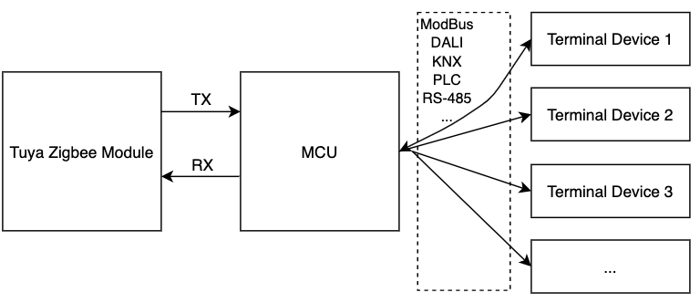
Tuya universal asynchronous receiver/transmitter (UART) protocol applies to the three-level architecture of Tuya Zigbee modules, the MCU, and terminal devices. It is used for the serial communication between the Tuya Zigbee modules and the directly-connected MCU repeaters. Terminal devices can be connected with repeaters through the wired mode. The architecture diagram is shown below.
This documentation is no longer updated. For more information, see Zigbee Serial Communication Protocol.
Hardware connection
Tuya Zigbee modules and MCU master control are both powered by DC 3.3V.
The UART communication Baud between Tuya Zigbee module and the MCU is set to 115200-8-N-1, and there is no data flow control. The UART interface pins use standard logic. In the idle status, the TXD and RXD pins are both high level, with the low level as the start bit and the high level as the stop bit. Even if the device enters sleep status, the pin remains at a high level.
Serial communication
Frame format
The UART communication data frame between Tuya Zigbee module and the MCU is composed of the frame header (Front), version (Ver), command (Cmd), data length (Length), data (Data), and checksum (Check). The definition and description are as follows.
| Octets: 2 | 1 | 2 | 1 | 2 | Variable | 1 |
|---|---|---|---|---|---|---|
| Front | Ver | Seq | Cmd | Length | Data | Check |
Frame format description
| Field | Description |
|---|---|
| Header (Front) | 2-byte leader character, fixed as 0x55aa |
| Version (Ver) | Serial communication protocol version for upgrade and extension |
| Sequence (Seq) | Transmission data serial number, ranging from 1 to 0xfff0, while other serial numbers are reserved for special functions |
| Command (Cmd) | For specific frame type, see the next table |
| Data length (Length) | The valid data length transmitted. The data length of a single frame does not exceed 100 bytes |
| Data (Data) | Valid data transmitted |
| Checksum (Check) | Data check. Start from the header, add up all the bytes, and then divide the sum by 256 to get the remainder |
Commands are described as follows:
| Cmd ID | Description |
|---|---|
| 0x01 | Query and report the product information |
| 0x02 | Query and report the device status |
| 0x03 | Reset the Zigbee device |
| 0x04 | The terminal device sends an adding request |
| 0x05 | The terminal device sends an adding request |
| 0x06 | RF test |
| 0x07 | Notify the MCU to synchronize data |
| 0x08 | Send a control command |
| 0x09 | Report the device status |
| 0x0B | Query the version |
| 0x0c | OTA notification |
| 0x0D | OTA request |
| 0x0E | OTA completion notification |
| 0x0C—0x23 | Reserved |
| 0x24 | Time synchronization |
-
All data greater than one byte shall be transmitted in big-endian mode.
-
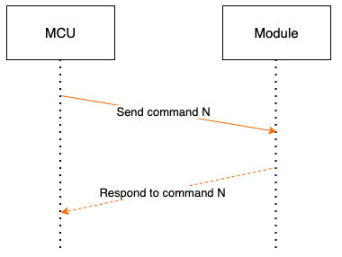
Generally, one command is sent by one party and received by the other party in a synchronous way. That is, one party sends the command, and the other party responds. If the sender does not receive the correct response packet within the specified time period, the transmission times out, as shown in the following figure:
Note: For specific communication modes, see the section Protocol details.
-
Sending module control commands and reporting MCU status works in an asynchronous way. Assuming that the control command of the module is x, and the command of MCU status reported is y, the data transmission is as follows.
Send the module control command: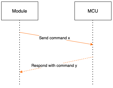
Report the MCU status:
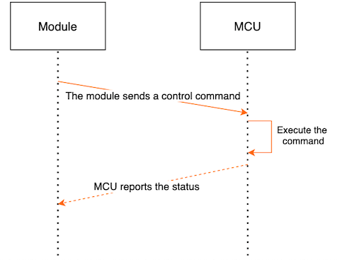
To report the MCU status, the module sends data commands to the MCU, and the MCU returns the status after execution.
Protocol details
Query product information of MCU
Product information consists of the product ID and MCU software version.
-
Product ID (PID) is generated in the Tuya Developer Platform to record product information in the cloud.
-
MCU software version number is in the dot-decimal format
X.X.X, in whichXis a decimal number. The actual MCU version is represented by one byte, and the bit allocation isxx.xx.xxxx. That is, the highest version that can be represented is 3.3.15.
For example, the module sends the following command:
| Field | Length (byte) | Description |
|---|---|---|
| Header | 2 | 0x55aa |
| Version | 1 | 0x02 |
| Serial number | 2 | N |
| Command | 1 | 0x01 |
| Data length | 2 | 0x0000 |
| Data | 0 | None |
| Checksum | 1 | Start from the header, add up all the bytes, and then divide the sum by 256 to get the remainder |
For example, 0x55aa 02 N 01 0000 xx.
The MCU returns the following command:
| Field | Length (byte) | Description |
|---|---|---|
| Header | 2 | 0x55aa |
| Version | 1 | 0x02 |
| Serial number | 2 | N |
| Command | 1 | 0x01 |
| Data length | 2 | N |
| Data | N | {"p":”AIp08kLI”, "v":”1.0.0” } |
| Checksum | 1 | Start from the header, add up all the bytes, and then divide the sum by 256 to get the remainder |
For example, {"p":” AIp08kLI”,"v":”2.0.0” }.
p represents the product ID, which is AIp08kLI.
v represents the MCU version number, which is 2.0.0.
0x55aa 02 N 01 00 1c 7b2270223a2241497031386b4c49222c2276223a22312e302e30227d xx
Report network status of the Zigbee module
| Device status ID | Description |
|---|---|
| 0x00 | The device is not connected to the gateway |
| 0x01 | The device is connected to the gateway |
| 0x02 | The device network status has an exception |
| 0x03 | The device is in the pairing status |
-
The device is not connected to the network: The device is powered on for the first time, fails to connect to the network, or is off the network. The status is sent to the MCU.
-
The device is connected to the network: The device is successfully connected to the network. The status is sent to the MCU.
-
When the module restarts or the power supply is cut off and then connected again, the module network status is actively sent to the MCU.
-
When the network status of the module changes, the module network status is actively sent to the MCU.
For example, the module sends the following command:
| Field | Length (byte) | Description |
|---|---|---|
| Header | 2 | 0x55aa |
| Version | 1 | 0x02 |
| Serial number | 2 | N |
| Command | 1 | 0x02 |
| Data length | 2 | 0x0001 |
| Data | 1 | Indicate the working status of the module: 0x00: status 1 and 0x01: status 2 |
| Checksum | 1 | Start from the header, add up all the bytes, and then divide the sum by 256 to get the remainder |
For example, 0x55aa 02 N 02 0001 00 xx.
The MCU returns the following command:
| Field | Length (byte) | Description |
|---|---|---|
| Header | 2 | 0x55aa |
| Version | 1 | 0x02 |
| Serial number | 2 | N |
| Command | 1 | 0x02 |
| Data length | 2 | 0x0000 |
| Data | 0 | None |
| Checksum | 1 | Start from the header, add up all the bytes, and then divide the sum by 256 to get the remainder |
For example, 0x55aa 02 N 02 0000 xx.
Configure the Zigbee module
There are two types of commands to configure the Zigbee module.
Note: After the MCU sends the network pairing command, the module will clear previous sub-devices. You need to re-add the sub-devices after successful network pairing.
| Command | Description |
|---|---|
| 0x00 | Reset the module software |
| 0x01 | Configure the module to start pairing (disconnect and then pair again). |
MCU sends the following command:
| Field | Length (byte) | Description |
|---|---|---|
| Header | 2 | 0x55aa |
| Version | 1 | 0x02 |
| Serial number | 2 | N |
| Command | 1 | 0x03 |
| Data length | 2 | 0x0001 |
| Data | 0 | 0x00/0x01 |
| Checksum | 1 | Start from the header, add up all the bytes, and then divide the sum by 256 to get the remainder |
For example, 0x55aa 02 N 03 0001 01 xx.
The module returns the following command:
| Field | Length (byte) | Description |
|---|---|---|
| Header | 2 | 0x55aa |
| Version | 1 | 0x02 |
| Serial number | 2 | N |
| Command | 1 | 0x03 |
| Data length | 2 | 0x0000 |
| Data | 0 | None |
| Checksum | 1 | Start from the header, add up all the bytes, and then divide the sum by 256 to get the remainder |
For example, 0x55aa 02 N 03 0000 xx.
The terminal device sends an adding request
This command is used when the MCU registers the terminal device with the Zigbee gateway.
Note: This command shall be sent after the module is successfully paired.
After the MCU sends the network pairing command, the module will clear the previous sub-devices. You need to re-add the sub-devices after successful network pairing.
MCU sends the following command:
| Field | Length (byte) | Description |
|---|---|---|
| Header | 2 | 0x55aa |
| Version | 1 | 0x02 |
| Serial number | 2 | N |
| Command | 1 | 0x04 |
| Data length | 2 | The length of actually transmitted data |
| The number of devices | 1 | The number (N) of devices is ≤10. No more than 10 devices can be registered in a single batch. If there are more than 10 devices, the data can be sent in two frames. |
| PID of the terminal device 1 | 8 | Device manufacturer number provided by Tuya |
| Address of the device 1 | 2 | Actual address of the device |
| PID of the terminal device 2 | 8 | Device manufacturer number provided by Tuya |
| Address of the device 2 | 2 | Actual address of the device |
| … | … | … |
| PID of the terminal device N | 8 | Device manufacturer number provided by Tuya |
| Address of the device N | 2 | Actual address of the device |
| Checksum | 1 | Start from the header, add up all the bytes, and then divide the sum by 256 to get the remainder |
The module returns the following command:
| Field | Length (byte) | Description |
|---|---|---|
| Header | 2 | 0x55aa |
| Version | 1 | 0x02 |
| Serial number | 2 | N |
| Command | 1 | 0x04 |
| Data length | 2 | 0x0000 |
| Data | 0 | None |
| Checksum | 1 | Start from the header, add up all the bytes, and then divide the sum by 256 to get the remainder |
The terminal device sends an adding request (extension)
This command is used when the MCU registers the terminal device with the Zigbee gateway.
Note: This command shall be sent after the module is successfully paired.
This protocol is for an extension. If the PID length exceeds 8 bytes, this command must be used.
The sub-device address is 2 bytes by default, and the Zigbee gateway will treat the address as a number. Therefore, even for devices with different PIDs, the address must be unique in the same Zigbee gateway.
After the MCU sends the network pairing command, the module will clear the previous sub-devices. You need to re-add the sub-devices after successful network pairing.
MCU sends the following command:
| Field | Length (byte) | Description |
|---|---|---|
| Header | 2 | 0x55aa |
| Version | 1 | 0x02 |
| Serial number | 2 | N |
| Command | 1 | 0x05 |
| Data length | 2 | Data length |
| PID length | To be determined | PID length |
| PID | To be determined | The product ID |
| The number of sub-devices | 1 | The number of sub-devices (M) |
| Sub-device address | 2*M | Registered sub-device addresses are arranged in order |
| Checksum | 1 | Start from the header, add up all the bytes, and then divide the sum by 256 to get the remainder |
The module returns the following command:
| Field | Length (byte) | Description |
|---|---|---|
| Header | 2 | 0x55aa |
| Version | 1 | 0x02 |
| Serial number | 2 | N |
| Command | 1 | 0x05 |
| Data length | 2 | 0x0000 |
| Data | 0 | None |
| Checksum | 1 | Start from the header, add up all the bytes, and then divide the sum by 256 to get the remainder |
Functional test of Zigbee devices
Scan the RSSI value of the specified channel, and return the scan result and signal strength percentage. This command can work properly only when the device is not paired, and the module must be restarted after a single test is completed.
When the channel is channel No. 11 to 26, channel No. 11 is used by default.
MCU sends the following command:
| Field | Length (byte) | Description |
|---|---|---|
| Header | 2 | 0x55aa |
| Version | 1 | 0x02 |
| Serial number | 2 | N |
| Command | 1 | 0x06 |
| Data length | 2 | 0x0001 |
| Data | Data | Channel value (11–26) |
| Checksum | 1 | Start from the header, add up all the bytes, and then divide the sum by 256 to get the remainder |
The module returns the following command:
| Field | Length (byte) | Description |
|---|---|---|
| Header | 2 | 0x55aa |
| Version | 1 | 0x02 |
| Serial number | 2 | N |
| Command | 1 | 0x06 |
| Data length | 2 | 0x0002 |
| Data | 2 | Data length has 2 bytes. Data[0]: 0x00 means failure, and 0x01 means success. When Data[0] is 0x01, which means success, Data[1] is signal strength (0-100, 0: the weakest signal, and 100: the strongest signal). When Data[0] is 0x00, which means failure, if Data[1] is 0x00, the RSSI is not found in the specified channel. If Data[1] is 0x01, the module has not generated an authorization key. |
| Checksum | 1 | Start from the header, add up all the bytes, and then divide the sum by 256 to get the remainder |
The valid channel value is 11 to 26. In case of an invalid channel, channel No. 11 will be used.
Notify the MCU to synchronize sub-device status
This notification will be sent after successful pairing.
This notification will also be sent after the gateway is powered off and then powered on again.
After receiving this command, MCU shall report the status of the sub-device. The length of the reported data cannot exceed 62 bytes. Otherwise, the data shall be reported in multiple packets.
For example, Zigbee sends the following command:
| Field | Length (byte) | Description |
|---|---|---|
| Header | 2 | 0x55aa |
| Version | 1 | 0x02 |
| Serial number | 2 | N |
| Command | 1 | 0x07 |
| Data length | 2 | 0x0000 |
| Checksum | 1 | Start from the header, add up all the bytes, and then divide the sum by 256 to get the remainder |
The module returns the following command:
| Field | Length (byte) | Description |
|---|---|---|
| Header | 2 | 0x55aa |
| Version | 1 | 0x02 |
| Serial number | 2 | N |
| Command | 1 | 0x07 |
| Data length | 2 | 0x0000 |
| Checksum | 1 | Start from the header, add up all the bytes, and then divide the sum by 256 to get the remainder |
Send a control command
The format of the command sending frame is as follows:
| Octets: 2 | 1 | 1 | 1 | 2 | 2 | Variable | 1 |
|---|---|---|---|---|---|---|---|
| Front | Ver | Seq | Cmd | Date Length | Address | Check |
| Octets: Variable | Variable | Variable | … | Variable |
|---|---|---|---|---|
| CmdData Unit-1 | CmdData Unit-2 | CmdData Unit-3 | … | CmdData Unit-n |
| Octets: 1 | 1 | 2 | Variable |
|---|---|---|---|
| Dpid | Type | Len | Value |
- Data point command and status data unit is shown as follows:
| Data segment | Length (byte) | Description | |
|---|---|---|---|
| Dpid | 1 | Data point serial number | |
| Type | 1 | The specific data type of a data point on the Developer Platform, which is marked with the following "Value". | |
| Type | Value | Length (byte) | Description |
| raw | 0x00 | N | Corresponding to the raw data point (module pass-through) |
| bool | 0x01 | 1 | Value range: 0x00 and 0x01 |
| value | 0x02 | 4 | Corresponding to the integer type, which is expressed in big-endian |
| string | 0x03 | N | Corresponding to a specific string |
| enum | 0x04 | 1 | Enumeration type, ranging from 0 to 255 |
| bitmap | 0x05 | 1/2/4 | Express in big-endian in case of more than 1 byte |
| Len | 2 | The length corresponds to the number of bytes of the value | |
| Value | 1/2/4/N | Express with hex, and adopt big-endian transmission in case of more than 1 byte |
-
For the data point command/status data unit, except the "raw" type, all other types belong to the "obj" type data point.
-
"Command sending" can contain "command data units" of multiple "obj" data points.
-
Command sending is an asynchronous processing protocol, corresponding to the data point status reporting of the MCU.
For example, the module sends the following command:
| Field | Length (byte) | Description |
|---|---|---|
| Header | 2 | 0x55aa |
| Version | 1 | 0x02 |
| Serial number | 2 | N |
| Command | 1 | 0x08 |
| Data length | 2 | It depends on the type and number of the command data unit and sub-device address length. |
| Sub-device address | 2 | Actual address of the device |
| Data | N | See the section Command data unit |
| Checksum | 1 | Start from the header, add up all the bytes, and then divide the sum by 256 to get the remainder |
The MCU returns the following command:
| Field | Length (byte) | Description |
|---|---|---|
| Header | 2 | 0x55aa |
| Version | 1 | 0x02 |
| Serial number | 2 | N |
| Command | 1 | 0x08 |
| Data length | 1 | 0x0003 |
| Sub-device address | 2 | Actual address of the device |
| Data | 1 | 0x00: success, 0x01: failure |
| Checksum | 1 | Start from the header, add up all the bytes, and then divide the sum by 256 to get the remainder |
Report the device status
- After the MCU receives the command sent by the module and executes the corresponding action, the MCU shall passively report the new status to the module.
After the status is executed correctly, only the data point status of the executed operation is reported.
-
Status reporting is processed in a synchronous manner. The module will immediately return an ACK to the MCU after receiving a message from the data point.
-
Status reporting can contain command data units of multiple data points.
-
The maximum length of the DP data is 59 bytes.
MCU sends the following command:
| Field | Length (byte) | Description |
|---|---|---|
| Header | 2 | 0x55aa |
| Version | 1 | 0x02 |
| Serial number | 2 | N |
| Command | 1 | 0x09 |
| Data length | 2 | It depends on the type and number of the status data unit and sub-device address length. |
| Sub-device address | 2 | Actual address of the device |
| Data | N | See the section Status data unit |
| Checksum | 1 | Start from the header, add up all the bytes, and then divide the sum by 256 to get the remainder |
The module returns the following command:
| Field | Length (byte) | Description |
|---|---|---|
| Header | 2 | 0x55aa |
| Version | 1 | 0x02 |
| Serial number | 2 | N |
| Command | 1 | 0x09 |
| Data length | 2 | 0x0003 |
| Sub-device address | 2 | Actual address of the device |
| Data | 0 | 0x00: The status is reported successfully, 0x01: Failed to report the status |
| Checksum | 1 | Start from the header, add up all the bytes, and then divide the sum by 256 to get the remainder |
Query MCU version
To support the MCU update, this command must be implemented, and it can also be actively reported by the MCU.
-
Query MCU version: 1. During pairing. 2. An exception occurred during the MCU update.
-
Active reporting MCU version: 1. After successful pairing (adding is required). 2. The update ends.
-
Version format: The maximum version that can be represented is 3.3.15. The version is represented by one byte, that is,
xx.xx.xxxx. But the gateway will not recognize the version information. The version information can be entered at will in the background, so the version data used by the MCU cannot exceed 3.3.15.
For example, the module sends the following command:
| Field | Length (byte) | Description |
|---|---|---|
| Header | 2 | 0x55aa |
| Version | 1 | 0x02 |
| Sequence (Seq) | 2 | Generated by the module |
| Command | 1 | 0x0B |
| Data length | 2 | 0x0000 |
| Data | 0 | |
| Checksum | 1 | Start from the header, add up all the bytes, and then divide the sum by 256 to get the remainder |
The MCU responds or the module sends the following command:
| Field | Length (byte) | Description |
|---|---|---|
| Header | 2 | 0x55aa |
| Version | 1 | 0x02 |
| Sequence (Seq) | 2 | Seq sent by the MCU |
| Command | 1 | 0x0B |
| Data length | 2 | 0x0001 |
| Data | 1 | Current version number: 01.00.0001 represents 1.0.1 |
| Checksum | 1 | Start from the header, add up all the bytes, and then divide the sum by 256 to get the remainder |
OTA updates notification
For example, the module sends the following command:
| Field | Length (byte) | Description |
|---|---|---|
| Header | 2 | 0x55aa |
| Version | 1 | 0x02 |
| Sequence (Seq) | 2 | Generated by the module |
| Command | 1 | 0x0c |
| Data length | 2 | 0x0011 |
| Data | 8 | Data[0]–Data[7] PID |
| Data | 1 | Version number after update: 01.00.0001 represents 1.0.1 |
| Data | 4 | Firmware size up to 256 KB |
| Data | 4 | Firmware checksum: Start from the first byte of the firmware, add up all the bytes, and then divide the sum by 2^32 to get the remainder |
| Checksum | 1 | Start from the header, add up all the bytes, and then divide the sum by 256 to get the remainder |
The MCU responds to the following command:
| Field | Length (byte) | Description |
|---|---|---|
| Header | 2 | 0x55aa |
| Version | 1 | 0x02 |
| Sequence (Seq) | 2 | Seq sent by the module |
| Command | 1 | 0x0c |
| Data length | 2 | 0x0001 |
| Data | 1 | 0x00: OK and 0x01: error |
| Checksum | 1 | Start from the header, add up all the bytes, and then divide the sum by 256 to get the remainder |
Request OTA firmware content
MCU sends the following command:
| Field | Length (byte) | Description |
|---|---|---|
| Header | 2 | 0x55aa |
| Version | 1 | 0x02 |
| Sequence (Seq) | 2 | 0x0000 |
| Command | 1 | 0x0D |
| Data length | 2 | 0x000c |
| Data | 8 | PID |
| Data | 1 | Version number after update: 01.00.0001 represents 1.0.1 |
| Data | 4 | The offset of the data packet (location of the firmware) |
| Data | 1 | Packet size |
| Checksum | 1 | Start from the header, add up all the bytes, and then divide the sum by 256 to get the remainder |
The module responds:
| Field | Length (byte) | Description |
|---|---|---|
| Header | 2 | 0x55aa |
| Version | 1 | 0x02 |
| Sequence (Seq) | 2 | 0x0000 |
| Command | 1 | 0x0D |
| Data length | 2 | 0x000e+N |
| Data | 1 | Status: 0 means success. 1 means failure. |
| Data | 8 | PID |
| Data | 1 | Version number after update: 01.00.0001 represents 1.0.1 |
| Data | 4 | The offset of the data packet (location of the firmware) |
| Data | N | Data |
| Checksum | 1 | Start from the header, add up all the bytes, and then divide the sum by 256 to get the remainder |
Report OTA firmware update result
This result shall be reported after the MCU update is completed. Regardless of the MCU update result, as long as the update is initiated, the update process must be terminated by the result reporting command.
MCU sends the following command:
| Field | Length (byte) | Description |
|---|---|---|
| Header | 2 | 0x55aa |
| Version | 1 | 0x02 |
| Sequence (Seq) | 2 | Seq sent by the MCU |
| Command | 1 | 0x0E |
| Data length | 2 | 0x000a |
| Data | 1 | Status: 0 means success. 1 means failure. |
| Data | 8 | PID |
| Data | 1 | Version number after update: 01.00.0001 represents 1.0.1 |
| Checksum | 1 | Start from the header, add up all the bytes, and then divide the sum by 256 to get the remainder |
The module responds:
| Field | Length (byte) | Description |
|---|---|---|
| Header | 2 | 0x55aa |
| Version | 1 | 0x02 |
| Sequence (Seq) | 2 | Seq sent by the MCU |
| Command | 1 | 0x0E |
| Data length | 2 | 0x0001 |
| Data | 1 | 0x00: OK and 0x01: error |
| Checksum | 1 | Start from the header, add up all the bytes, and then divide the sum by 256 to get the remainder |
Time synchronization
Time synchronization is used for the MCU to test the network time that is synchronized with the gateway.
MCU sends the following command:
| Field | Length (byte) | Description |
|---|---|---|
| Header | 2 | 0x55aa |
| Version | 1 | 0x02 |
| Serial number | 2 | N |
| Command | 1 | 0x24 |
| Data length | 2 | 0x0000 |
| Data | Data | NA |
| Checksum | 1 | Start from the header, add up all the bytes, and then divide the sum by 256 to get the remainder |
The module returns the following command:
| Field | Length (byte) | Description |
|---|---|---|
| Header | 2 | 0x55aa |
| Version | 1 | 0x02 |
| Serial number | 2 | N |
| Command | 1 | 0x024 |
| Data length | 2 | 0x0002 |
| Data | 2 | The time value has 8 bytes. For more information about the format, see the following time synchronization data format. |
| Checksum | 1 | Start from the header, add up all the bytes, and then divide the sum by 256 to get the remainder |
The data format of time synchronization includes a standard timestamp and a local timestamp.
| Variable | Variable |
|---|---|
| Standard timestamp (4 bytes) | Local timestamp (4 bytes) |
Data format of time synchronization
The standard timestamp is the total seconds from GMT 00:00:00, January 1, 1970 to the current time.
Local timestamp = standard timestamp + the difference in seconds between standard time and local time (including time zone and daylight saving time).
Is this page helpful?
YesFeedbackIs this page helpful?
YesFeedback


