LZ201 Module OpenCPU SDK Demo
This topic describes the OpenCPU SDK-based application template that features adaptive generation of data point (DP) code. The DP definition varies depending on your requirements for product features. To improve your efficiency in coding with Tuya’s SDK, we have developed an application template based on the OpenCPU SDK.
Overview
The template provides the featured adaptive generation of DP code and basic service capabilities. For example, activate devices, reset network connection, authorize devices, test calibration, configure serial communication, enable GPS feature, and process DP events.
Development environment
-
Operating system: Linux
-
Development environment: Python 3.7.2
Download the Python 3.7.2 source package.wget https://www.python.org/ftp/python/3.7.2/Python-3.7.2.tar.xz && \ tar -xvf Python-3.7.2.tar.xz && \ cd Python-3.7.2 && \ ./configure --with-ssl --enable-shared && make && sudo make altinstall
Get the template
The template is included in the OpenCPU SDK. You need to create a product on the Tuya IoT Platform to get the SDK.
-
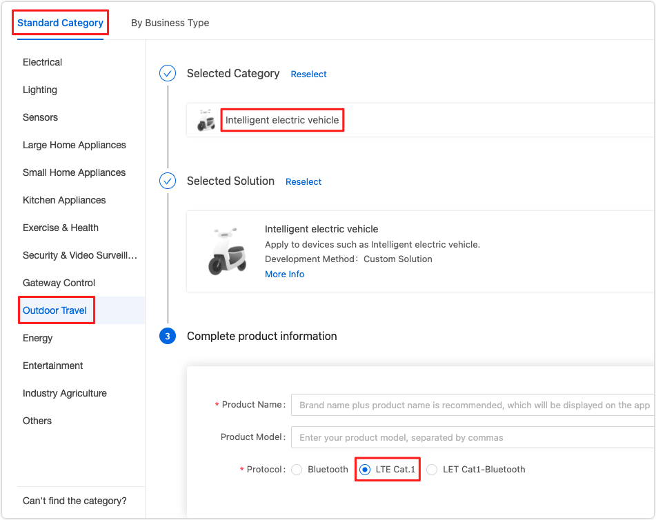
Log in to the Tuya IoT Platform.
-
Select Outdoor Travel > Intelligent electric vehicle. Complete the production information and select LTE Cat.1 as the protocol.
-
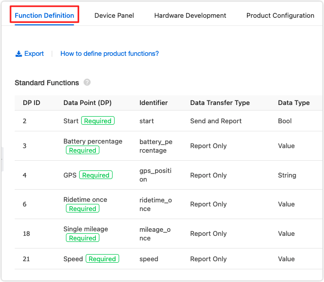
In the first step of Function Definition, add the required Standard Functions.
-
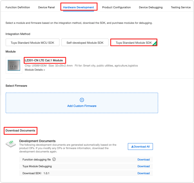
In the third step of Hardware Development, select Tuya Standard Module SDK. Scroll down the page and find Development Documents. Download the function debugging file and SDK.
-
Extract the SDK and you can find the
templatein the apps folder.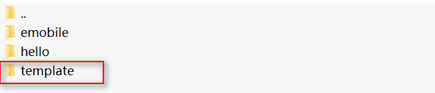
Directory structure
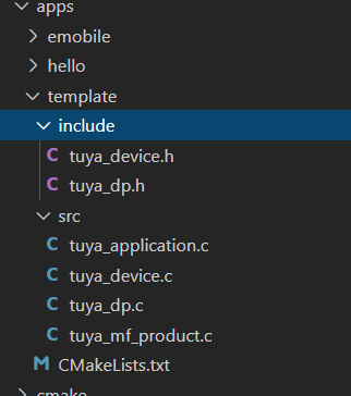
The apps folder in the extracted archive has the following structure:
-
Folder
Folder name Description template The application template of the OpenCPU. emobile Sample code based on the application template. hello SDK sample code. -
File
File name Description tuya_device.h Contains struct, macros, production information, and public headers for all .cfiles except thetuya_dp.c.tuya_dp.h Contains function definitions, DP definitions, and product ID (PID) for tuya_dp.c.tuya_application.c Contains the source code to implement different features. tuya_device.c Contains configuration information and entry functions. tuya_dp.c Contains code of DP, including the interface functions for transmitting DP data and commands. tuya_mf_product.c Contains entry functions for the production test.
Compilation
Copy the downloaded function debugging file to a folder in the OpenCPU SDK directory. In the sibling directory of apps, pass the path of the debugging file, DP’s header file, and .c file as command line parameters to the executable file. The functions and definitions for DPs will be automatically generated.
In this topic, the debugging file is put in the /apps/template directory. We run the following commands.
./tools/tuya_dp_tool/tuya_dp_tool ./apps/template/template.json ./apps/template/include/tuya_dp.h ./apps/template/src/tuya_dp.c
Then, run ./build.sh in the OpenCPU SDK directory to generate the application firmware. If the compilation succeeds, you will find the compiled binary files in the specified directory.
Template features
The following block diagram shows the process to start an application.
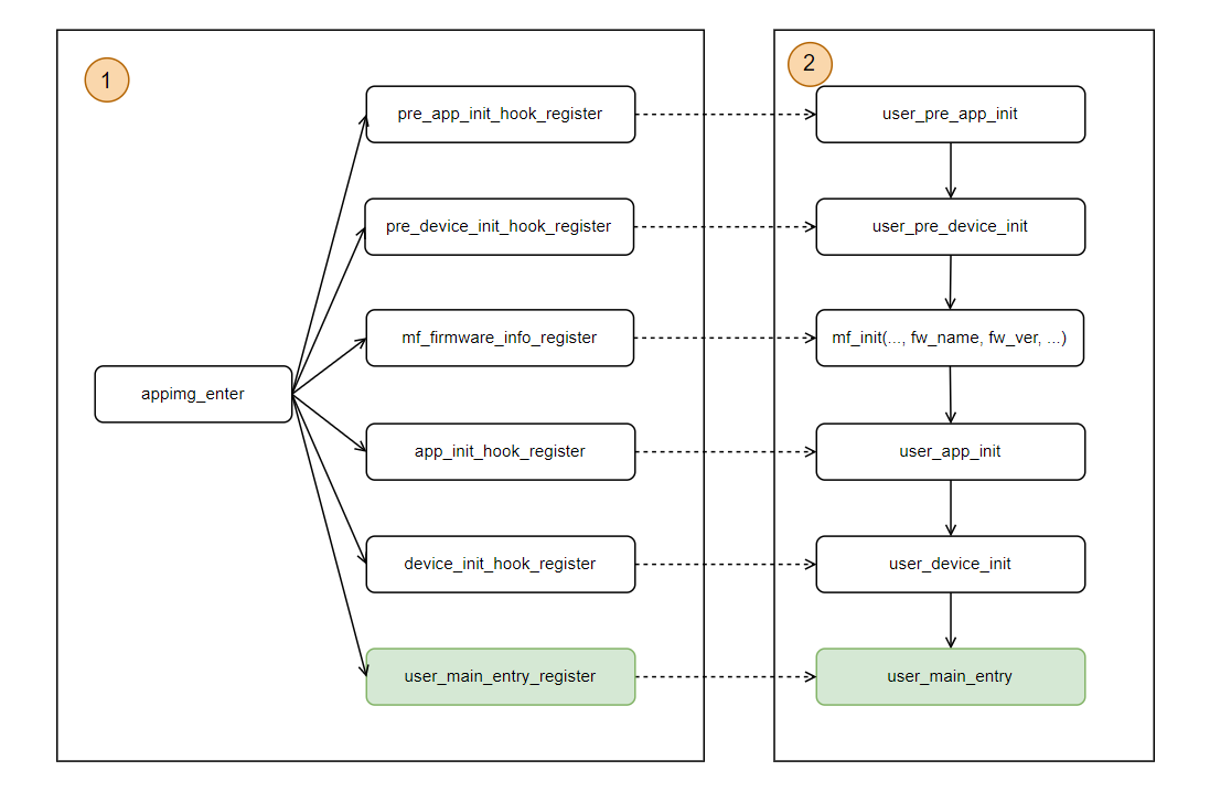
After the system loads the application, call the appimg_enter and register the required functions. The following is the description of functions.
pre_app_init_hook_register: Registers the defined functionuser_pre_app_initthat implements required application initialization before the production test. If you do not implement the production test feature, it is unnecessary to callpre_app_init_hook_registerand implementuser_pre_app_init.pre_device_init_hook_register: Registers the defined functionuser_pre_device_initthat implements required device initialization before the production test. If you do not implement the production test feature, it is unnecessary to callpre_device_init_hook_registerand implementuser_pre_device_init.mf_firmware_info_register: Registers firmware information, including the firmware name and version number.mf_initpasses the firmware information to the system in the production test. If you do not call this function, the firmware information defaults to the system firmware name and version number.app_init_hook_register: Registers the defined functionuser_app_initthat implements required application initialization after the production test. If you do not implement the production test feature, it is unnecessary to callapp_init_hook_registerand implementuser_app_init.device_init_hook_register: Registers the defined functionuser_device_initthat implements required device initialization after the production test. If you do not implement the production test feature, it is unnecessary to calldevice_init_hook_registerand implementuser_device_init.user_main_entry_register: Registers the defined functionuser_main_entrythat is the entry of the application and used to start the application functionality. You must implementuser_main_entryand calluser_main_entry_registerto complete registration.
After the system is started, call user_pre_app_init > user_pre_device_init > mf_init > user_app_init > user_device_init > user_main_entry to complete the initialization process.
Activation
You must set the APN before device activation. Otherwise, the activation will fail. tuya_device.c contains the function to specify an access point name (APN). See the sample code below.
/**
 * @brief   Preparation before initialization
 *
 * @return  VOID_T
 *
 * @note   The application executes the required configuration and initialization before the production test.
 *
 * @note   You need to implement a null function if you do not use this function.
 */

VOID_T user_pre_app_init(VOID_T)
{
	/* If the APN is not specified, it will be automatically set by the system. */
	tuya_cellular_srv_mds_pdp_active(NULL,NULL,NULL);
	PR_NOTICE("user_pre_app_init succ");
}
In tuya_application.c, register firmware and product information through the OpenCPU function interface.
/**
 * @brief   Device activation and network listener
 *
 * @param   VOID
 *
 * @return   0: success. -1: failure
 */
OPERATE_RET tuya_device_init()
{
	...
	op_ret = tuya_iot_cat1_opencpu_dev_init(&wf_cbs, g_dev_info.firware_key, g_dev_info.prod_key, g_dev_info.sys_fw_ver, g_dev_info.app_fw_ver, mcu_sw_ver);
	if (OPRT_OK != op_ret)
	{
		PR_ERR("tuya_device_init err:%d", op_ret);
		return op_ret;
	}
	...

	return op_ret;
}
Authorization and calibration test
The hardware can work properly only with correct authorization and calibration. Authorization and calibration test and error logs can help you in debugging. See the sample code below.
OPERATE_RET tuya_device_init()
{
	...
	/* Test authorization and calibration. If the hardware is not authorized, an error code will be returned. */
	if(0 == get_gw_cntl()->gw_base.auth_key[0] || (0 == get_gw_cntl()->gw_base.uuid[0]))
	{
		PR_DEBUG("please write uuid and auth_key first");
		return OPRT_COM_ERROR;
	}
	...

	bool ret = tuya_hal_cellular_calibrated();
	if(!ret)
	{
		PR_DEBUG("Not calibrated ret/%d", ret);
		return OPRT_COM_ERROR;
	}
	lan_pro_cntl_disable();

	return op_ret;
}
UART configuration
The template takes UART1 as an example to show how to initialize and configure the serial port. You need to implement specific UART features as needed.
/**
 * @brief   UART initialization function
 *
 * @param   VOID
 *
 * @return   0: success. -1: failure
 *
 * @note   Configure UART parameters. To use the UART feature, you must initialize the configuration.
 */
OPERATE_RET uart_init(VOID)
{
	OPERATE_RET op_ret;
	demo_uart = tuya_driver_find(TUYA_DRV_UART, TY_UART_INDEX);
	if (NULL == demo_uart)
	{
		PR_ERR("uart1 find failed");
		return OPRT_COM_ERROR;
	}
	// Configures UART parameters.
	TUYA_UART_8N1_CFG(demo_uart, 115200, 1024, 0);
	// Initializes UART.
	op_ret = tuya_uart_init(demo_uart);
	if (OPRT_OK != op_ret)
	{
		PR_ERR("uart init failed", op_ret);
		return OPRT_COM_ERROR;
	}
	return op_ret;
}
GPS
Enable or disable the GPS feature and get GPS data including speed, longitude, latitude, and signal strength. The LZ211 module and LZ201 module differ in the GPS feature. Therefore, you can use macros to identify the module and implement functions accordingly.
TY_MODULE_TYPE defaults to 0xFF. This way, both the LZ211 module and the LZ201 module disable GPS. To enable GPS, set TY_MODULE_TYPE according to the specific module and reboot the module.
#define TY_MODULE_TYPE 0xFF // 0: LZ201 module. 1: LZ211 module.
For more information about code implementation, see the code in the template.
Battery level and signal strength
With a timer, you can get the battery level and signal strength of the module. You can call the data reporting interface to send the data to the Tuya IoT Cloud.
STATIC VOID send_battery_info_msg(UINT_T timerID, PVOID_T pTimerArg)
{
	PR_DEBUG("enter get_gps_info");
	tuya_msg_send(PROC_BAT_EVENT,1);
}

OPERATE_RET tuya_add_timer_func(VOID)
{
	OPERATE_RET op_ret = OPRT_OK;
	...
	/* Get the battery level and signal strength of the module. */
	op_ret = sys_add_timer(send_battery_info_msg, NULL, &ty_msg.get_battery_info_timer);
	if(OPRT_OK != op_ret)
	{
		return op_ret;
	}

	return op_ret;
}

STATIC VOID ty_msg_proc(VOID *param)
{
	UCHAR_T option  = 0;
	OPERATE_RET ret = OPRT_OK;

	while(1)
	{
		ret = tuya_hal_queue_fetch(ty_msg.pQueue_event, &option, 1000);
		if (ret == OPRT_OK)
		{
			...
			if(option == PROC_BAT_EVENT)
			{
				UCHAR_T battery_val;
				SCHAR_T rssi;
				   /* Process the battery level. */
				tuya_cellular_battery_get_rsoc(&battery_val);
				   /* Get the GSM signal strength. */
				tuya_hal_cellular_get_rssi(&rssi);
			}
		}
	}
}
DP processing
Reception and execution of commands
In the function tuya_device_init, the callbacks tuya_obj_dp_cmd_cb for DP processing is registered. When the application receives data, tuya_obj_dp_cmd_cb calls ty_obj_datapoint_proc to process the received DP data and execute an operation accordingly. Then, the data reporting function will be called to send the DP status to the application.
OPERATE_RET tuya_device_init()
{
	OPERATE_RET op_ret = OPRT_OK;

	 /* Activate the device, register DP data callback, and listen for the network. */
	TY_IOT_CBS_S wf_cbs = {
		.dev_obj_dp_cb   = tuya_obj_dp_cmd_cb,
		.dev_raw_dp_cb   = tuya_raw_dp_cmd_cb,
		.dev_dp_query_cb = tuya_dp_query_cb,
	};
	...
	return op_ret;
}

/**
 * @brief   Process DP data of raw type.
 *
 * @param   DP
 *
 * @return  No value returned
 *
 * @note   This function is optional. Implement it as needed.
 */
VOID tuya_obj_dp_cmd_cb(IN CONST TY_RECV_OBJ_DP_S *dp)
{
	PR_DEBUG("app_obj_dp_cmd_cb ... ...");

	if (!get_gw_dev_cntl()->dev_if.bind)
	{
		PR_ERR("dev is not bind");
		return;
	}

	if (!dp || dp->dps_cnt == 0)
	{
		PR_ERR("no valid dp");
		return;
	}
	INT_T i = 0;

	 // Parses the DP data sent from the cloud.
	for (;;)
	{
		tuya_obj_datapoint_proc((TY_OBJ_DP_S *)&dp->dps[i]);
		if (++i < dp->dps_cnt)
			tuya_hal_system_sleep(40);
		else
			break;
	}
}

/**
 * @brief  Processing function for DP data of object type
 *
 * @param  obj_dp
 *
 * @return   No value returned
 *
 * @note   This function is optional. Implement it as needed.
 */
STATIC VOID tuya_obj_datapoint_proc(TY_OBJ_DP_S *obj_dp)
{
	switch(obj_dp->dpid)
	{
	// Code of this part is automatically generated.
[TEMPLATE_DP_HANDLE]

		default:
		break;
	}
}
Adaptive generation of DP code
tuya_dp.c and tuya_dp.h contains code for the adaptive generation. We recommend that you do not modify these two files. Contact our technical support if modification is necessary.
You can go through the tuya_dp.c and tuya_dp.h files and see the section Compilation for compiling. After successful compilation, you will have interface functions in tuya_dp.c and tuya_dp.h, including DP definitions, PID definitions, and DP processing functions.
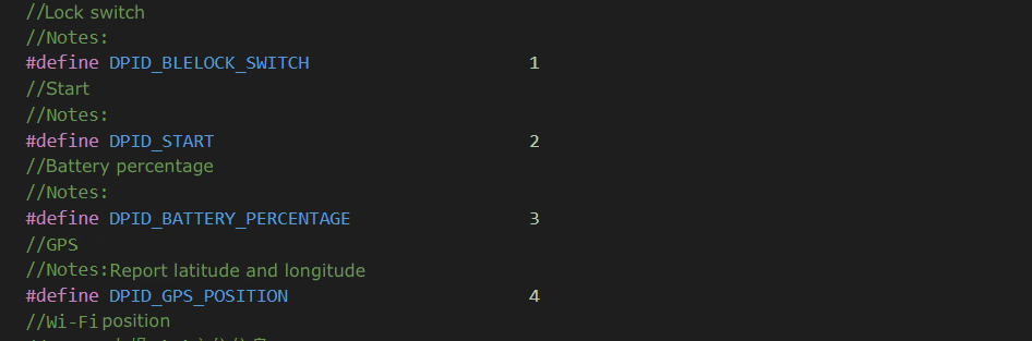
The following figure shows how adaptive generation works. Before the generation:
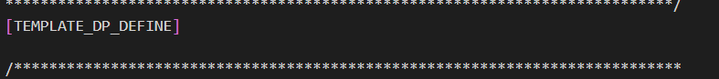
After the generation:
Instance
This section takes the smart electric vehicle as an example to show you how the template works. We added two features to the current template, namely single or multiple DP reporting and firmware updates.
Create a smart product
See the section Get the template to create a smart electric vehicle and get the SDK and debugging file.
Code description
The following describes how the device interacts with the cloud.
-
The device interacts with the cloud in JSON. The DP identity and definition have been set in the first step of creating a product on the Tuya IoT Platform.
tuya_dp.hcan automatically generate DP information. For more information, see the section Adaptive generation of DP code. -
The PID is generated when a product is created on the Tuya IoT Platform. As the unique identity of a device, the PID is associated with product configurations, such as app UI and cloud configuration. Therefore, the PID must be written to the code.
tuya_dp.hcan write the PID through a macro. For more information, see the section Adaptive generation of DP code.
We added two features to the current template, namely single or multiple DP reporting and firmware updates.
| Feature | Implementation |
|---|---|
| DP processing | Report single DP or multiple DPs in a group. |
| MCU firmware update | We configure the serial port protocol and show you how the MCU firmware update works. |
Generate DP functions and definition
-
Duplicate the
templatefolder in the OpenCPU SDK directory and rename it to your product name. The name of this instance isemobileso we rename the copy toemobile. -
To clear the generated binary files, run the following command in the OpenCPU directory.
./build.sh cleanSelect the target number, as shown below.
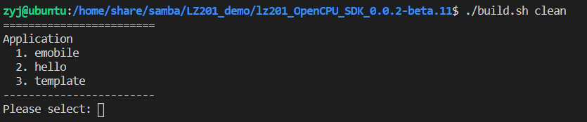
If clearing is not necessary, you can skip this step. When you compile new binary files, the old ones will be overwritten.
-
Copy the downloaded function debugging file to the directory created for your product. Our directory is
emobileso this debugging file is put in/apps/emobile/.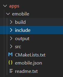
-
Run the following command in the sibling directory of
appsto generate DP information../tools/tuya_dp_tool/tuya_dp_tool ./apps/emobile/emobile.json ./apps/emobile/include/tuya_dp.h ./apps/emobile/src/tuya_dp.c -
Go to
tuya_dp.handtuya_dp.cto check the execution result. -
Run the following command to compile and check results.
emobileis the target for compilation and0.0.1is the target version../build.sh emobile 0.0.1
DP processing
The timer function is required for DP data reporting initiated by the module. This function can implement scheduled reporting.
/**
* @brief   Add the interface function for a timer
*
* @param   VOID
*
* @return   0: success. Other values: failure
*/
OPERATE_RET tuya_add_timer_func(VOID)
{
	OPERATE_RET op_ret = OPRT_OK;
	...
	/* Get the battery level and signal strength of the module. */
	op_ret = sys_add_timer(send_battery_info_msg, NULL, &ty_msg.get_battery_info_timer);
	if(OPRT_OK != op_ret)
	{
		return op_ret;
	}

	return op_ret;
}

/**
* @brief   Start the specified timer.
*
* @param   VOID
*
* @return   0: success. Other values: failure
*/
OPERATE_RET ty_start_timer_func(VOID)
{
	OPERATE_RET op_ret = OPRT_OK;
	...
	op_ret = sys_start_timer(ty_msg.get_battery_info_timer, BAT_INFO_REPORT_INTERVAL, TIMER_CYCLE);
	if (op_ret != OPRT_OK)
	{
		PR_DEBUG("bat info report timer start failed!");
		return op_ret;
	}
	return op_ret;
}
Report a single DP
When the status of a DP changed, the interface function is called to report the status value of a single DP ID. Take the data type of value as an example. See the sample code below.
/**
 * @brief   Event processing thread
 *
 * @param Parameters of a thread can be null.
 *
 * @return  No value returned
 */
STATIC VOID ty_msg_proc(VOID *param)
{
	UCHAR_T option  = 0;
	OPERATE_RET ret = OPRT_OK;

	while(1)
	{
		ret = tuya_hal_queue_fetch(ty_msg.pQueue_event, &option, 1000);
		if (ret == OPRT_OK)
		{
			PR_DEBUG("ty_msg_proc option = %d", option);
			if (option == PROC_GPS_EVENT)
			{
				DWORD_T speed = ty_gps_get_speedinfo();
				...
				tuya_dp_value_update(DPID_SPEED, speed);
				...
			}
			...
		}
	}
}

/**
 * @brief   Pass the DP ID and its value to the reporting function.
 *
 * @param   dpid: the DP ID of a data point added on the Tuya IoT Platform
 * @param   dp_value: the value of a data point whose status changed
 */
VOID tuya_dp_value_update(UCHAR_T dpid, INT_T dp_value)
{
	TY_OBJ_DP_S dp;
	memset(&dp, 0, sizeof(dp));
	switch(dpid)
	{
	case DPID_SPEED:
	{
		dp.dpid = dpid;
		dp.type = PROP_VALUE;
		dp.value.dp_value = dp_value;
		OPERATE_RET op_ret = dev_report_dp_json_async(get_gw_cntl()->gw_if.id, &dp, 1);
		if(OPRT_OK != op_ret)
		{
			PR_ERR("dev_report_dp_json_async op_ret:%d",op_ret);
		}
	}
	break;

	default:
	break;
	}
}
Report multiple DPs
Report the status of multiple DPs in one packet. You need to encapsulate the data with the following struct.
typedef struct {
	UINT_T          dps_cnt;
	TY_OBJ_DP_S     *dps;
} TY_DP_DATA_S;
The following sample code shows how to get the battery level as well as the signal strength of the module.
/**
* @brief   Event processing thread
*
* @param Parameters of a thread can be null.
*
* @return  No value returned
*/
STATIC VOID ty_msg_proc(VOID *param)
{
	UCHAR_T option  = 0;
	OPERATE_RET ret = OPRT_OK;

	while(1)
	{
		ret = tuya_hal_queue_fetch(ty_msg.pQueue_event, &option, 1000);
		if (ret == OPRT_OK)
		{
			PR_DEBUG("ty_msg_proc option = %d", option);
			...

			if (option == PROC_BAT_EVENT)
			{
				Multiple_Dp_Report_Test(battery_val, rssi);
				...
			}
		}
	}
}

/**
* @brief   Report status of multiple DPs in one packet.
*
* @param   None
*
* @return  No value returned
*/
STATIC VOID Multiple_Dp_Report_Test(UCHAR_T battery_val, SCHAR_T rssi)
{
	// Sample code is as follows.
	TY_DP_DATA_S multiple_dp;
	OPERATE_RET ret;
	multiple_dp.dps = tuya_hal_system_malloc(128);
	multiple_dp.dps_cnt = 2;

	multiple_dp.dps[0].dpid = DPID_BATTERY_PERCENTAGE;
	multiple_dp.dps[0].type = PROP_VALUE;
	multiple_dp.dps[0].value.dp_value = battery_val;
	multiple_dp.dps[1].dpid = DPID_SIGNAL_STRENGTH;
	multiple_dp.dps[1].type = PROP_VALUE;
	multiple_dp.dps[1].value.dp_value = rssi;

	if (ty_msg.netstatus == 4)
	{
		PR_DEBUG("enter Multiple_Dp_Report_Test");
		ret = dev_report_dp_json_async(get_gw_cntl()->gw_if.id, multiple_dp.dps, multiple_dp.dps_cnt);
		if (ret != OPRT_OK)
		{
			PR_DEBUG("dp report failed");
		}
		else
		{
			PR_DEBUG("dp report successed");
		}
	}
	return;
}
Firmware update
This section describes how to implement the firmware update feature.
Extension firmware update
Note: The extension firmware is the one you build based on the OpenCPU SDK.
The extension firmware update feature has been implemented in the system firmware. Therefore, you only need to set the update strategy and upload your firmware to deploy the updates. If you set the update method to update notification, users will receive a firmware update notification in the mobile app and choose whether to install updates. The following block diagram shows the update process.
Click Update to install all available updates.
MCU firmware update
-
Serial port protocol
Protocol format
Frame header + version + command +
data_len+ data + parity- Frame header: The format of
0x7e81is used. - Version:
0x00indicates the module, and0x03indicates the MCU. - Command: used to control the interaction between the MCU and the module.
0x0a: starts the update.0x0b: transmits data.0x0d: gets the MCU version. data_len: the length of the data transmitted in the command.data: data transmitted in the command.- Parity
- Frame header: The format of
-
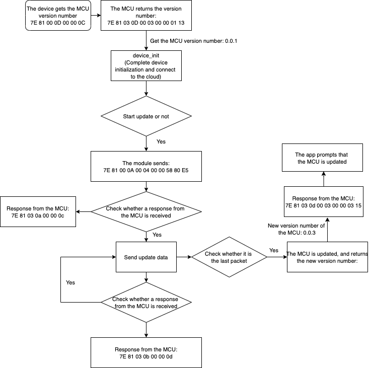
Function implementation
The principle of extension firmware update also works on MCU firmware update. The module communicates with the MCU through the UART. The following figure shows how it works.
Before you test the MCU update feature, you need to define
MCU_EXISTmacro. See the sample code below.Step 1: The template has implemented the code of UART initialization so you need to add a thread to process the UART after the initialization.
OPERATE_RET uart_init(void)
{
	OPERATE_RET op_ret;
	...
#ifdef MCU_EXIST
	op_ret = tuya_hal_mutex_create_init(&ty_msg.mutex);
	if (op_ret != OPRT_OK)
	{
		PR_ERR("create mutex err");
		return op_ret;
	}
	op_ret = tuya_hal_semaphore_create_init(&ty_msg.mcu_ug_sem, 0, 1);
	if (op_ret != OPRT_OK)
	{
		PR_ERR("create semphore err");
		return op_ret;
	}
	 // Creates a thread to listen for serial data.
	PR_DEBUG("creat uart_init uart recv task");
	THRD_PARAM_S thrd_uart_param;
	THRD_HANDLE ty_uart_handle = NULL;
	thrd_uart_param.priority = TUYA_UART_MONITOR_TASK_PRIORITY;
	thrd_uart_param.stackDepth = TUYA_UART_MONITOR_TASK_HEAP_SIZE;
	thrd_uart_param.thrdname = "ty_uart_monitor_thread_task";
	op_ret = CreateAndStart(&ty_uart_handle, NULL, NULL,
							ty_uart_monitor_thread, NULL, &thrd_uart_param);
	 // Starts the timer for getting the MCU version.
	sys_start_timer(ty_msg.get_cur_mcu_ver_timer, GET_MCU_VER_TIME,TIMER_CYCLE);
#endif
	return op_ret;
}
Step 2: Register the update callback.
OPERATE_RET device_init(void) { ... if (0 != tuya_cat1_register_mcu_fota_inform_hook(mcu_start_upgrade_cb)) { PR_ERR("register mcu fota inform hook failed"); } if (0 != tuya_cat1_register_mcu_fota_process_hook(mcu_upgrade_process_cb)) { PR_ERR("register mcu fota process hook failed"); } if(0 != tuya_cat1_register_mcu_fota_notify_hook(mcu_ug_complete_notify_cb)) { PR_ERR("register mcu fota notify hook failed"); } PR_NOTICE("register mcu fota hooks succ"); op_ret = tuya_iot_cat1_opencpu_dev_init(&wf_cbs, firmware_key, product_key, sys_fw_ver, app_fw_ver, mcu_sw_ver); ... return op_ret; }Note: The callback must be registered before the function
tuya_iot_cat1_opencpu_dev_initis called.Step 3: Implement code of the callback
When the update starts, the module will send the update size and version number by calling
mcu_start_upgrade_cb. This function can notify the MCU of update preparation.void mcu_start_upgrade_cb(UINT_T fileSize, const CHAR_T* version, const CHAR_T* fwHMAC) { PR_NOTICE("mcu_start_upgrade_cb start to upgrade mcu firmware"); PR_NOTICE("fw_hmac: %s", fwHMAC); PR_NOTICE("fw version: %s", version); PR_NOTICE("fw fileSize: %d", fileSize); tuya_hal_semaphore_post(ty_msg.mcu_ug_start_sem); ... UCHAR_T buf[11] = {0x7E,0x81,0x00,0x00,0x00,0x00,0x00,0x00,0x00,0x00,0xff}; ty_msg.mcu_file_size = fileSize; buf[3] = 0x0A; buf[5] = 0x04; buf[6] = (fileSize >> 24) & 0xFF; buf[7] = (fileSize >> 16) & 0xFF; buf[8] = (fileSize >> 8) & 0xFF; buf[9] = fileSize & 0xFF; UCHAR_T num = getCheckSum(buf, 10); buf[10] = num; // Sends the initial data to the MCU through the UART write function. tuya_uart_write(demo_uart, buf, sizeof(buf)); // Resends data in case of a timeout. sys_start_timer(ty_msg.mcu_ug_fw_timer, MCU_RECV_TIME * 1000, TIMER_ONCE); ... return; }Process and send the update data in the function
mcu_upgrade_process_cb.// In this instance, we assume that the UART has a 256-byte buffer for data receiving and sending. You can set the buffer to 512-byte or 1024-byte as needed. static void mcu_upgrade_process_cb(UINT_T offset, const BYTE_T* data, UINT_T len) { ... if (dev_proc.send_len + mcu_ug_buff_len + len >= dev_proc.file_size) is_last_file_pack = TRUE; // Indicates the flag of the last packet. copy_len = MIN(send_unit_len - mcu_ug_buff_len, len); memcpy(&(buff[mcu_ug_buff_len]), data, copy_len); mcu_ug_buff_len += copy_len; data_offset = copy_len; if (mcu_ug_buff_len == send_unit_len) { mcu_ug_buff_len = 0; ret = upgrade_file_cb(buff, send_unit_len); // Sends data through the UART. if (OPRT_OK != ret) { PR_ERR("MCU upgrade file failed"); return; } dev_proc.send_len += send_unit_len; } while (data_offset + send_unit_len <= len) { ret = upgrade_file_cb(&(data[data_offset]), send_unit_len); if (OPRT_OK != ret) { PR_ERR("MCU upgrade file failed"); return; } data_offset += send_unit_len; dev_proc.send_len += send_unit_len; } if (is_last_file_pack) { if (mcu_ug_buff_len) { ret = upgrade_file_cb(buff, mcu_ug_buff_len); mcu_ug_buff_len = 0; if (OPRT_OK != ret) { PR_ERR("MCU upgrade file failed"); return; } dev_proc.send_len += mcu_ug_buff_len; } if (data_offset < len) { ret = upgrade_file_cb(&(data[data_offset]), len - data_offset); if (OPRT_OK != ret) { PR_ERR("MCU upgrade file failed"); return; } dev_proc.send_len += len - data_offset; } PR_NOTICE("[MCU_FOTA]: upgrade mcu fw succ: %d, %d", dev_proc.send_len, dev_proc.file_size); } else if (data_offset < len) { memcpy(buff, &(data[data_offset]), len - data_offset); mcu_ug_buff_len = len - data_offset; } return; }mcu_ug_complete_notify_cbnotifies the cloud of completion of update transmission. You can implement the serial protocol in this function to notify the MCU of the completion of update transmission.static VOID mcu_ug_complete_notify_cb(INT_T result) { if (OPRT_OK == result) { ... PR_NOTICE("mcu upgrade succ"); return; } ... }Then, the MCU writes the firmware to the flash memory. The latest MCU version number is sent to the application through the UART. The application calls
tuya_iot_cat1_update_mcu_verin the SDK to send the latest version number to the cloud to notify the mobile app of a successful update.static INT_T ty_uart_data_proc(UCHAR_T* data) { OPERATE_RET op_ret = OPRT_OK; UCHAR_T buf[] = {0}; TY_FRAME_S *ty_frame = (TY_FRAME_S *)data; PR_DEBUG("frame type: %d", ty_frame->fr_type); switch (ty_frame->fr_type) { ... case GET_MCU_VER: { dev_sw_ver = tuya_hal_system_malloc(11); if (IsThisSysTimerRun(ty_msg.get_cur_mcu_ver_timer)) { sys_stop_timer(ty_msg.get_cur_mcu_ver_timer); } buf[0] = ty_frame->data[0]; buf[1] = ty_frame->data[1]; buf[2] = ty_frame->data[2]; memset(dev_sw_ver, 0, 11); sprintf(dev_sw_ver, "%d.%d.%d", buf[0], buf[1], buf[2]); PR_DEBUG("ty_uart_monitor_thread mcu_ug_ver: %s\r\n", dev_sw_ver); if (!ty_msg.init_flag) { ty_msg.init_flag = 1; // Connects to the cloud. op_ret = device_init(); if (OPRT_OK != op_ret) { PR_ERR("app_init_entry device_init err: %d", op_ret); return op_ret; } } // Sends the latest MCU version number to the cloud. Set ty_msg.mcu_ug_ctrl to 1 after the data is transmitted. else if (ty_msg.mcu_ug_ctrl) { sys_stop_timer(ty_msg.mcu_ug_fw_timer); op_ret = tuya_iot_cat1_update_mcu_ver(mcu_sw_ver); if (op_ret != OPRT_OK) { sys_start_timer(ty_msg.mcu_sync_ver_timer, 100, TIMER_ONCE); PR_DEBUG("op_ret/%d", op_ret); } } tuya_hal_system_free(mcu_sw_ver); } break; default: break; } return op_ret; }
Compile the firmware
The SDK includes a script for compilation. You can run the following command to call the script for compiling.
-
Command: Navigate to the directory of the script and run
./build_app.sh <your project name> <version number>. -
Sample command:
./build.sh emobile 0.0.1
After successful compilation, a binary file (with the . pac extension) will be generated in the apps/your project name/output/version number/ directory, as shown below.
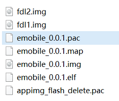
Then, you can flash this binary file to the device.
Debugging
This section describes how to test the features of your device.
Add a device
There are two methods for you to add a device.
-
Method 1: Scan a QR code
The QR code is printed by Tuya’s tool. Contact Tuya’s account manager or submit a service ticket to request support.
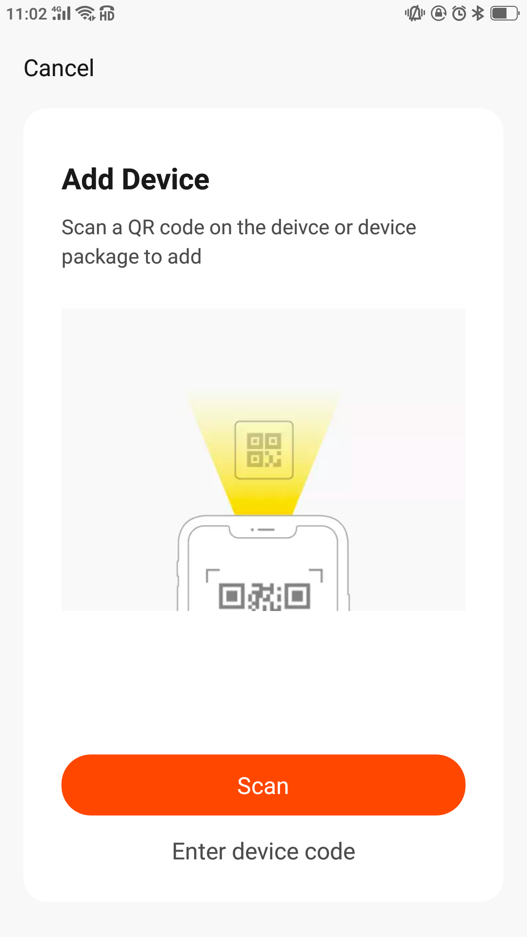
-
Method 2: Connect through Bluetooth
-
Download the Tuya app from Apple Store or mobile app stores.
-
Register and log in.
-
Tap + > Auto Scan > Enable Bluetooth > Start scanning.
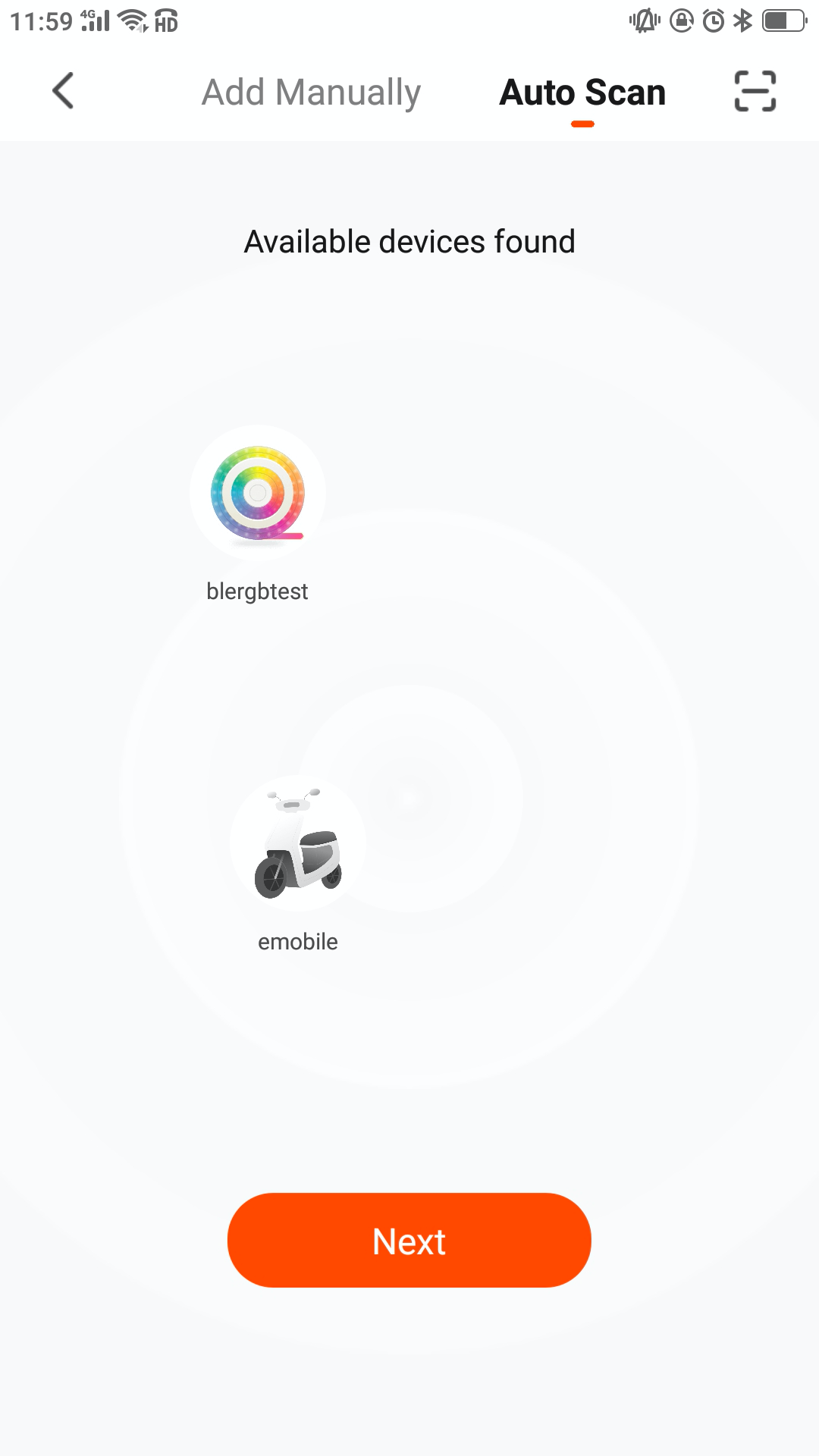
-
After the device is found, tap Next to start pairing. After pairing is completed, the control panel appears by default.
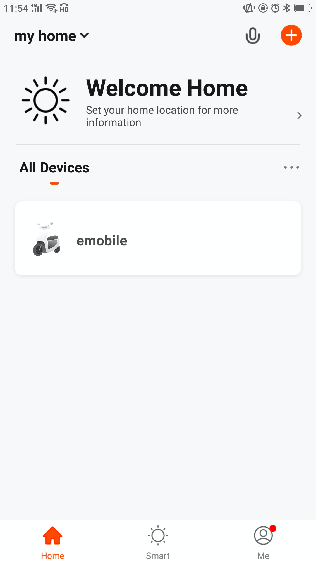
-
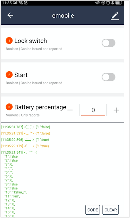
Test DP processing
On the control panel, tap each DP to test data sending and receiving.
Is this page helpful?
YesFeedbackIs this page helpful?
YesFeedback


