TYDE 3.0 Development Board
Last Updated on : 2024-06-24 01:36:31download
Introduction
TYDE3.0 Tuya Smart IoT development board is an IoT prototype platform provided by Hangzhou Tuya Information Technology. Developers can quickly realize all kinds of hardware demo by using TYDE3.0. To make hardware smart, they will need professional support team in smart cloud platform, mobile App and Wi-Fi networking module besides hardware. TYDE3.0 integrates the Wi-Fi module and MCU, connects the Tuya Cloud and App. Developers can experience the use of IoT products once they get the development boards. The development board is equipped with the STM32F103C8T6 so developers can start development instantly after they get it and enjoy developing smart hardwares. TYDE3.0 helps:
- Embedded software engineers of manufacturers to use TYDE3.0 for early-stage development and debugging of embedded software program.
- App developers to use TYDE3.0 for App development and debugging before the hardware control board is available.
- Makers to use TYDE3.0 to quickly realize the hardware demo and use mobile phone to control hardware.
- IoT technophiles to understand the principles of IoT and learn the smart hardware product development.
Recommendations on how to use TYDE3.0:
| Steps | Description | Quick Link |
|---|---|---|
| Get familiar with functions of the development board | Introduction of main parts and components of the development board and use of each button | Introduction of TYDE3.0 hardware platform |
| Try Tuya app | TYDE3.0 has built-in demo hardware, and users can add it directly on Tuya app to experience the whole process. | Try to use the Tuya app development board |
| Start smart hardware product development | Register an account in Tuya Development Platform and start your own smart hardware development. | Start smart hardware product development |
Introduce of Hardware Platform
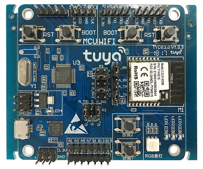
The Wi-Fi module of TYDE3.0 development board will be the high performance Wi-Fi module TYWE1S developed by Tuya or ESP-12F developed by the Ai-Thinker. Both TYWE1S and ESP-12F use Espressif ESP8266 Wi-Fi chips. The development board includes Wi-Fi MODULE, STM32F103C8T6 single Chip microcomputer, USB-serial port conversion chip and multiple LED indicator lights, IO interfaces for development by developers and power, etc. It can be an MCU for users and connected to Wi-Fi module of built-in Tuya Smart firmware, and it can also be used by users to experience the operation performance of all types of Tuya Smart products. For developers in enterprises, it accelerates the progress of projects and product development. The development board is powered up through a USB MICRO-B port and builds in a USB-to-serial circuit, for users to conduct module test upgrade and project development in a convenient, quick, and flexible way. The details are given in the following figure.
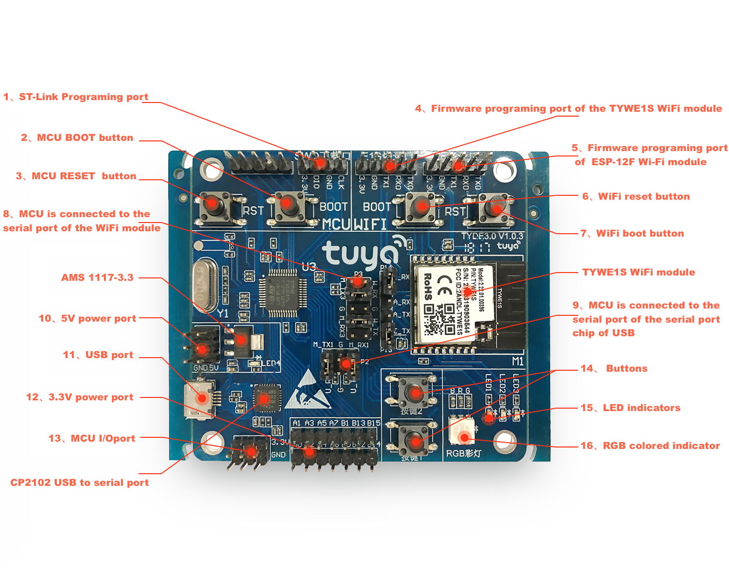
Functions of interfaces are given below:
- ST-Link programing port: program downloading port in SWD mode for STM32 single-chip microcomputer;
- MCU BOOT button: must be pressed during serial programing;
- MCU RESET button: hardware reset button of STM32 single-chip microcomputer;
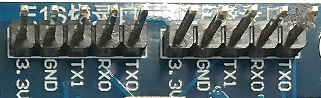
- Firmware programing port of the TYWE1S Wi-Fi module: it is used to check the operation information of the TYWE1S module and program the TYWE1S firmware (Please do not program the firmware by yourself, and do contact our company if you need to program it.).
- Firmware programing port of ESP-12F Wi-Fi module: it is used to check the operation information of ESP-12F module and program ESP-12F firmware (Please do not program the firmware by yourself, and do contact our company if you need to program it.).
- Wi-Fi reset button: both TYWE1S and ESP-12F Wi-Fi module use the hardware reset.
- Wi-Fi boot button: it is used when programing hardwares in TYWE1S and ESP-12F Wi-Fi modules.
- MCU is connected to the serial port of the Wi-Fi module. When the short-circuit block is plugged, the MCU is connected to the serial port of the Wi-Fi module.
- MCU is connected to the serial port of the serial port chip of USB. When the short-circuit block is plugged, the MCU is connected to the serial port of CP2102 chip.
- 5V power port: output 5V voltage and GND
- USB port: USB Micro-B port, it is connected to USB of computers
- 3.3V power port: output 3.3V voltage and GND
- MCU I/O port: I/O pin of MCU, for users’ own development
- Buttons: have two buttons, connected to the I/O pin of MCU
- LED indicators: LED1 and LED2 are connected to MCU, LED3 is connected to Wi-Fi module, on at low level
- RGB colored indicator: connected to MCU, on at low level.
Precautions and Recommended Steps for Use
Precautions
- TYDE3.0 Tuya Smart IoT Development Board is equipped with TYWE1S Wi-Fi module by default. Users can also change 2 resistors by themselves so that ESP-12F Wi-Fi module can be used.
- Please do not program the original firmware of TYWE1S. Otherwise the authorization information in TYWE1S may be lost and the network configuration mode of Tuya Smart cannot be used. If you do need to develop Wi-Fi firmware by yourself, please contact Tuya for technical guidance.
Recommended Steps for Use
- When you get the development board, please connect it to the power supply with the Android wire so that the development board can check functions of the board by itself. For details, please refer to the operation guidance in the next document.
- If all functions of the development board are normal, LED1 indicator will flash quickly (the on-off cycle is about 0.5s). Then, uses have to download and register the Tuya app on their mobile phones prior to the network configuration. For details, please refer to the operation guidance in document four.
- If you are familiar with or have mastered the Tuya Smart network configuration, you can proceed to open the project files based on STM32F103C8T6 provided by Tuya to further study Accessing Protocols and Procedures of Open IoT Universal Serial Port of Tuya Smart. For details, please refer to the operation guidance in document five.
- Then you can connect STM32 or your own MCU to TYWE1S or ESP-12F Wi-Fi module to develop your own products independently. For details, please refer to the operation guidance in document six.
- If you mistakenly erased the original firmware in STM32 single chip microcomputer or you need to update the firmware of STM32 single chip microcomputer, the last document will teach you how to easily program STM32 firmware.
Self-testing and Inspection of Development Board
The user only needs to install the support column and then connect an Android wire to the development board. Then, the following steps should be followed to test the functions of the development board.
-
Set a Wi-Fi signal with SSID as “tuya_mdev_test” by cell phone hotspot or router.
-
Wait for several seconds until indicator LED1 is on (continuously on, quick flash or slow flash);
-
Press button 2 for more than three seconds and then release, and “16RGB” colored indicator will be red, blue,green and white sequentially. Then, test Wi-Fi functions of TYWE1S module. After 3-5 seconds, the test for Wi-Fi functions of Wi-Fi module is completed. In this case, the colors of “16 RGB colored indicator” and corresponding test results are as follows:
| RGB Colored Indicator | Test Result | Operation Scheme & Solution |
|---|---|---|
| Blue | The tested Wi-Fi functions are normal. | Implement the next step. |
| Red | SSID “Tuya _ mdev _ test” does not exist. | Set and inspect “Tuya _ mdev _ test”. |
| Red | SSID “tuya_mdev_test” is too far from the Wi-Fi module of the development board. | Shorten the distance between them. |
| Red | The Wi-Fi module on the development board is abnormal. | Contact us to replace the development board. |
| Green | The Wi-Fi module on the development board is unauthorized. | Contact us to replace the development board. |
| No response | The communication between STM32 and Wi-Fi module port is failed. | Contact us to replace the development board. |
Note: If you are using an older version, after you press button 2 for more than three seconds and then release, and “16RGB” colored indicator will be red, blue,green and white sequentially.If the blue indicator is on, it means the Wi-Fi test functions are normal. If the green indicator is on, it means the Wi-Fi module on the development board is unauthorized.
4 . Press button 1 when the RGB colored indicator is blue, and it will turn into white. Press button 1 again, and RGB colored indicator will be off.
5 . When the self-testing of the development board is completed, the network can be configured by a cell phone with Tuya app downloaded and registered.
Experience of Development Board by Tuya app
Downloading of Tuya app
Please search and download Tuya app in App Store or Android App Market. The App can also be downloaded by scanning the QR code.

Adding of Development Board by App
There are two modes for network configuration of Tuya Smart device, i.e., SmartConfig Mode and AP Mode. LED1 flashes quickly in compatible mode and flashes slowly in AP Mode. The user can press “Button 1” on the development board for about 5S to switch the state.
- Adding development in SmartConfig Mode
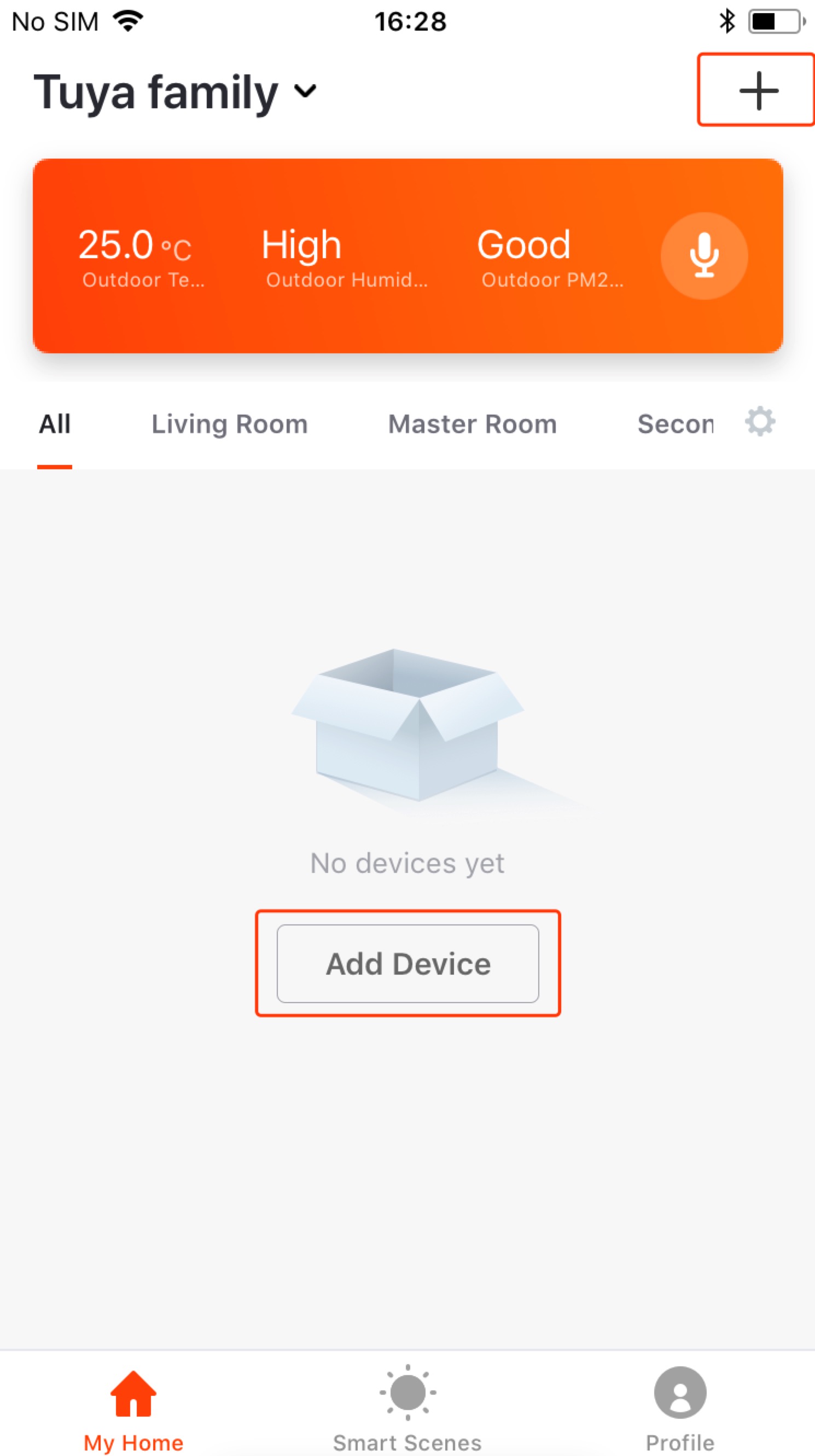
Please press “Button 1” for 5S first to make LED1 flash quickly, because the default mode of Tuya app is SmartConfig Mode. Open Tuya app to add the device by clicking “+” in the upper right corner on the page of “My Home”.
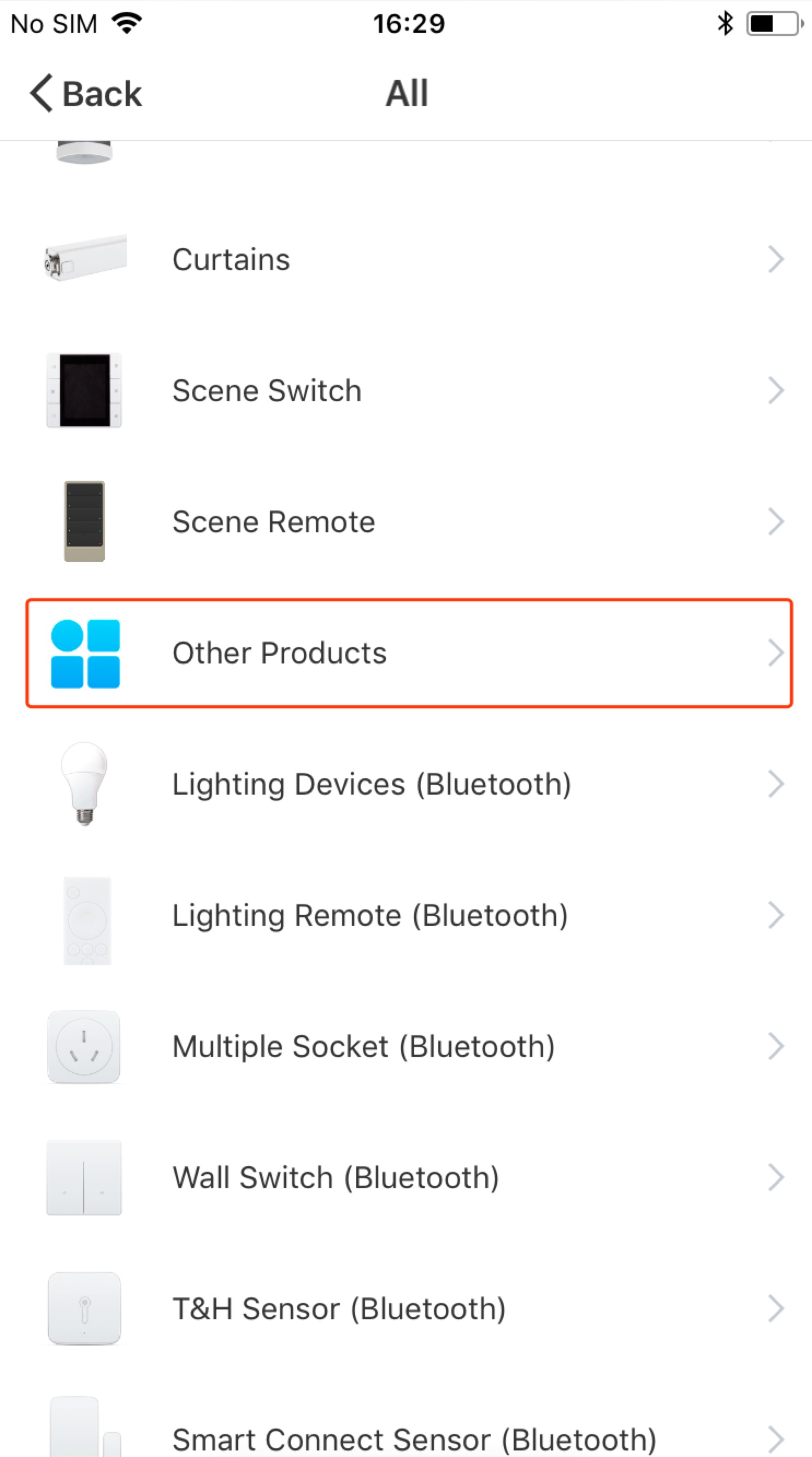
Go to the interface of device type selection and select “Others” in “All Devices” as shown in the figure below.
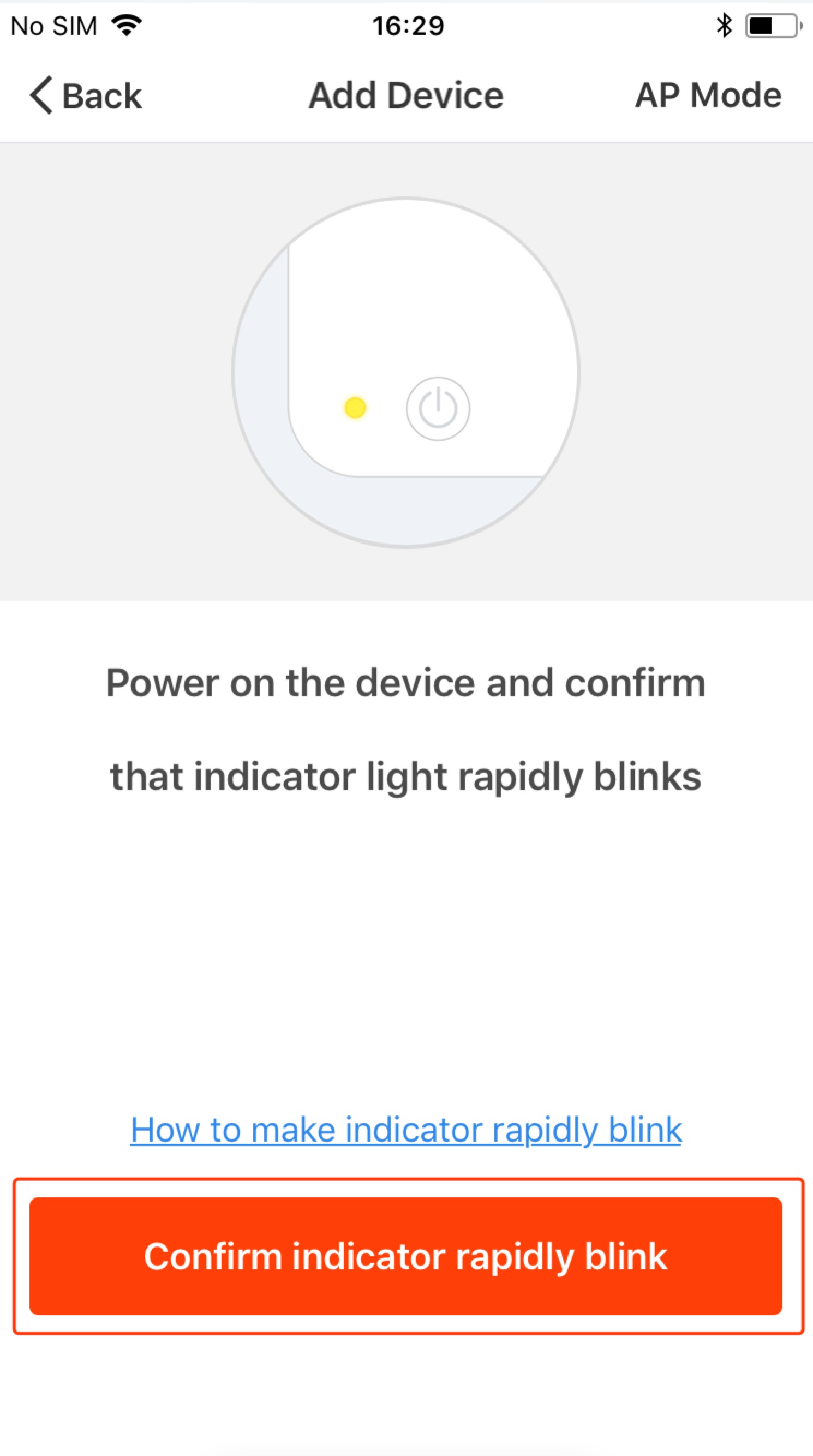
Recheck whether LED1 is flashing quickly and then click “Confirm indicator rapidly blink” to continue the operation.
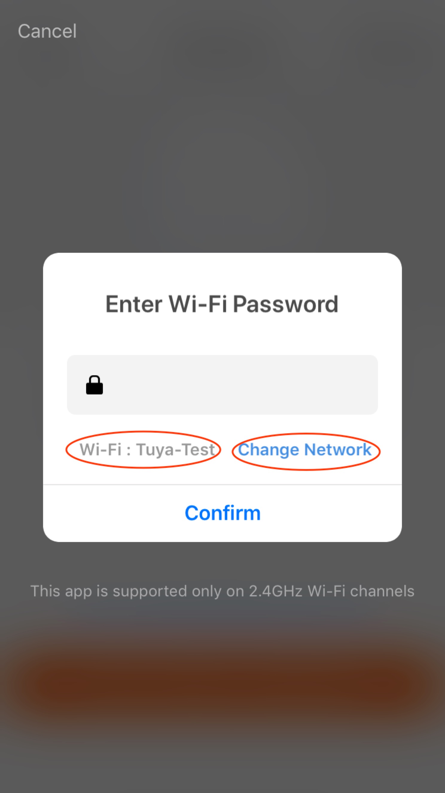
Select the Wi-Fi to be connected by the device and enter the password. Click “Confirm” after entry.
Supplementary Instructions: the device working Wi-Fi refers to the desirable Wi-Fi router for network connection of the device. Inform the device of router SSID and password by Tuya app. The device will remember the router SSID and password, and then it is allowed to connect to the Internet via this Wi-Fi.
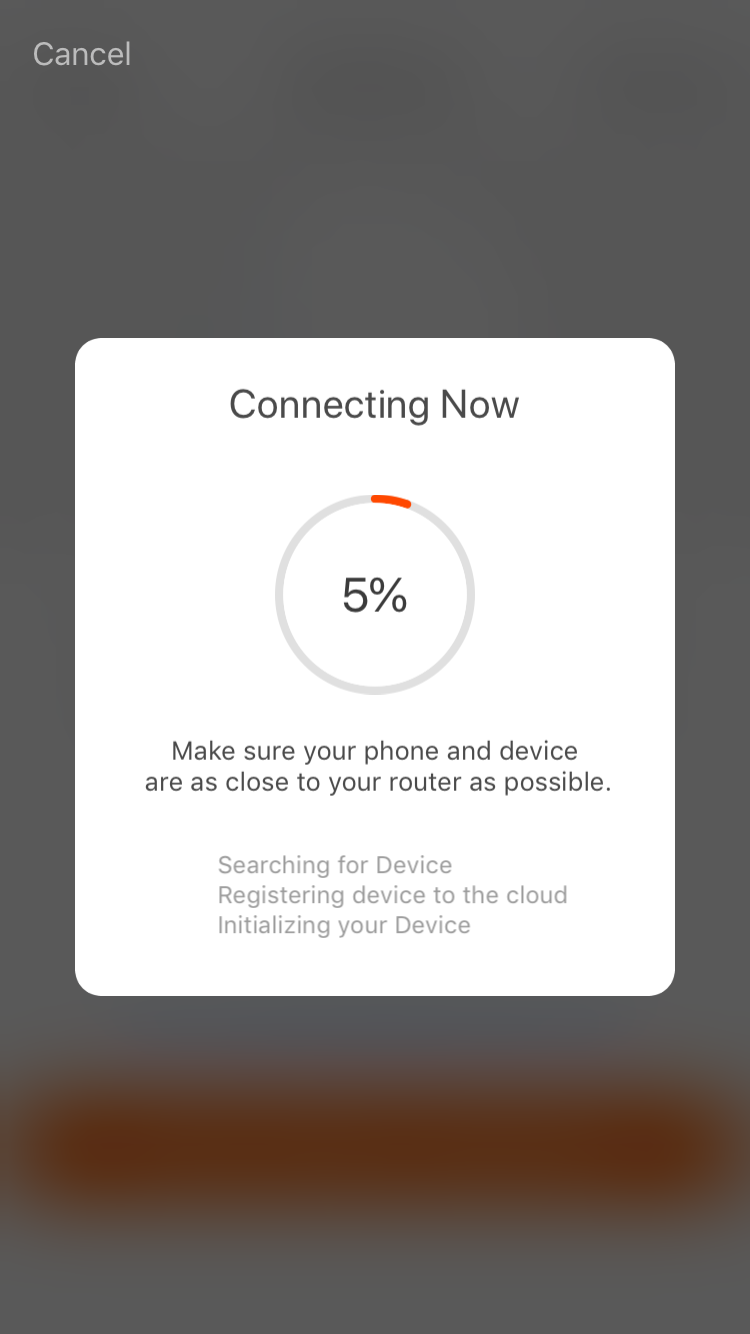
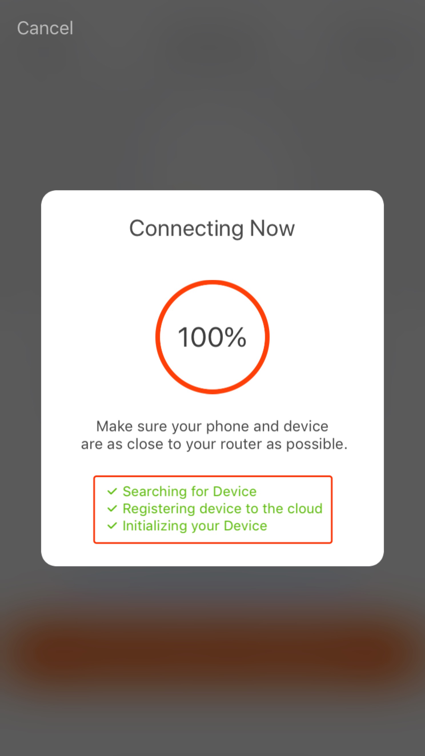
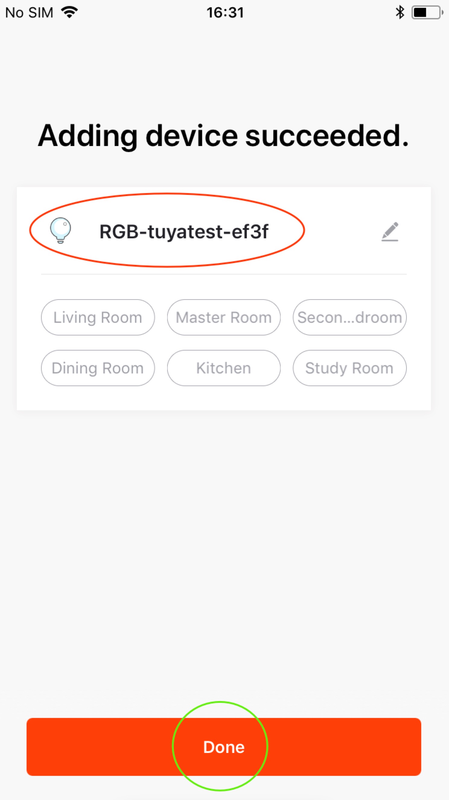
When you get here, you will wait for a while, mobile phones, routers, and development boards will start to quietly “send the secret code” to each other. After about 20 seconds, the Wi-Fi module on the development board will establish a connection with the mobile phone and router. Just click “Done” here.
- Experience of demo function of development board
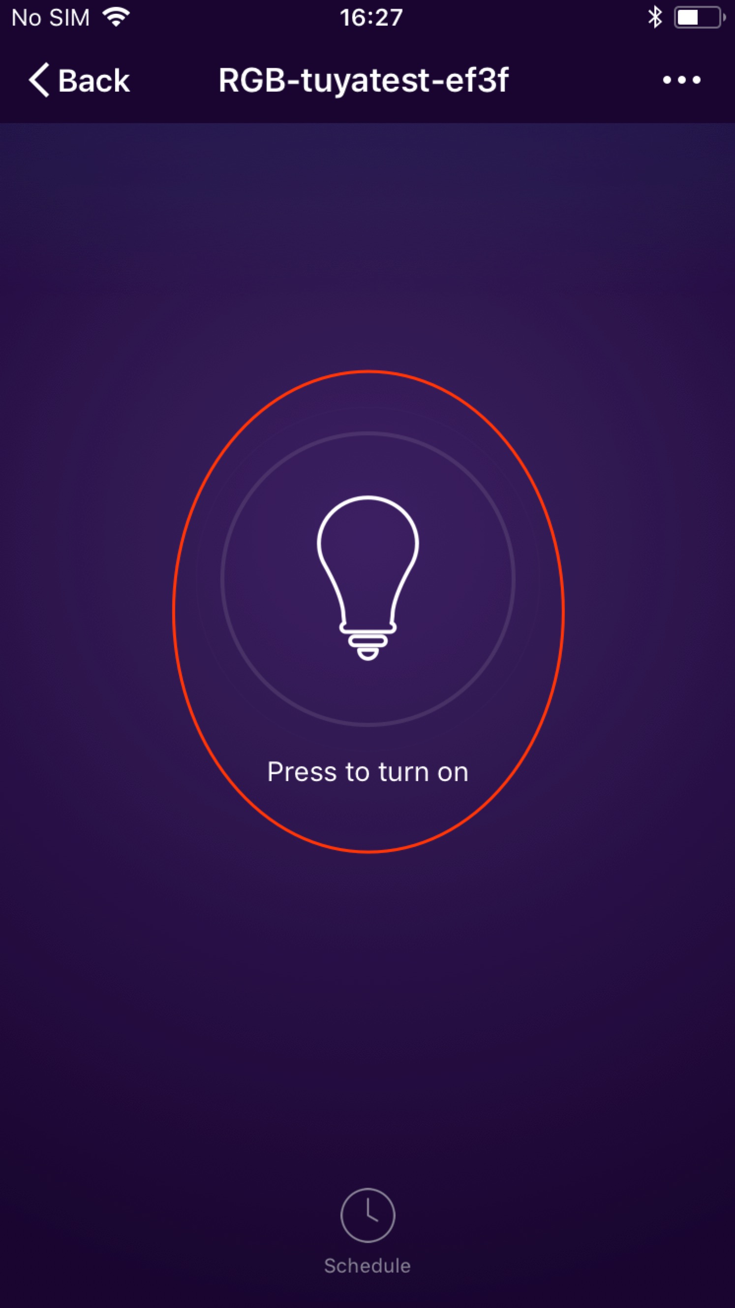
When entering the device control page, you will see the App interface shown in the following figure. In this case, RGB colored indicator on the development board is off. Click the red circle area in the figure below, and RGB colored indicator will be on. Is it amazing? The following will be more wonderful.
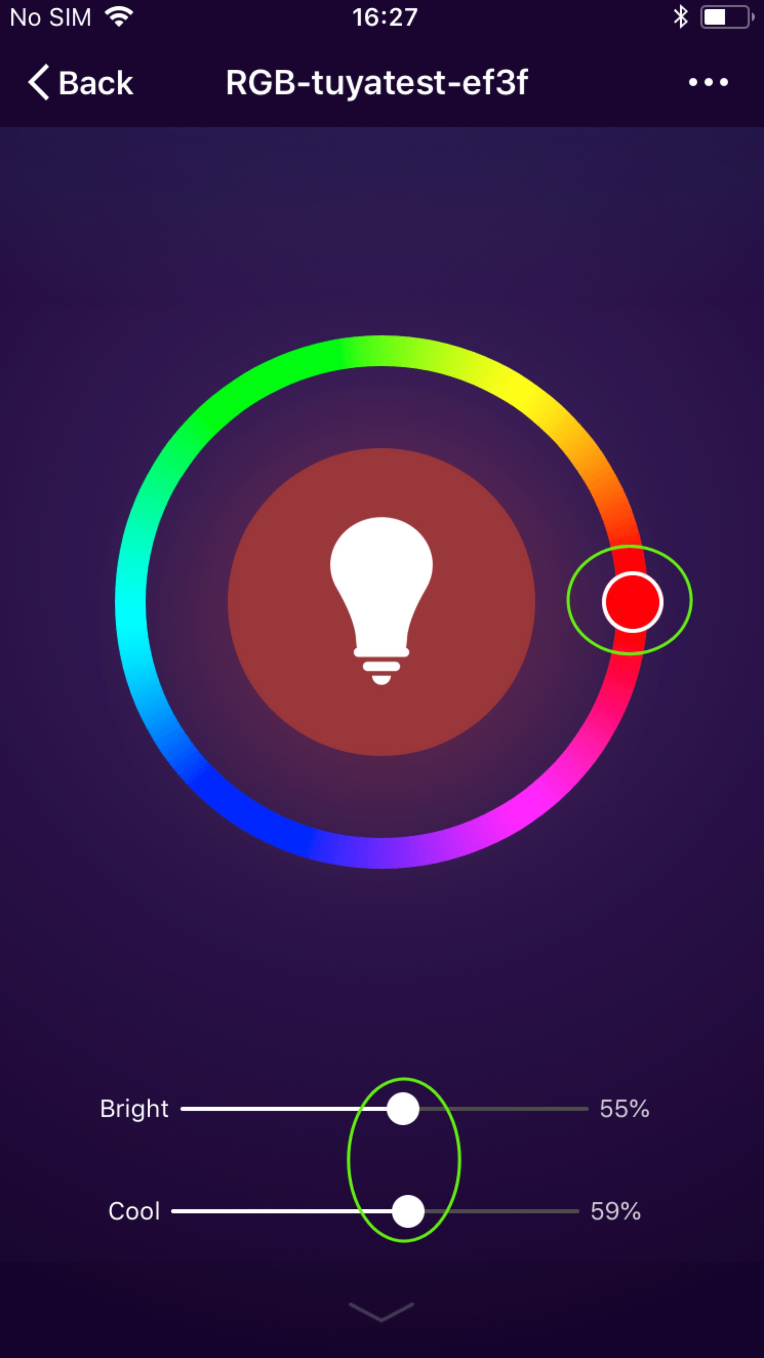
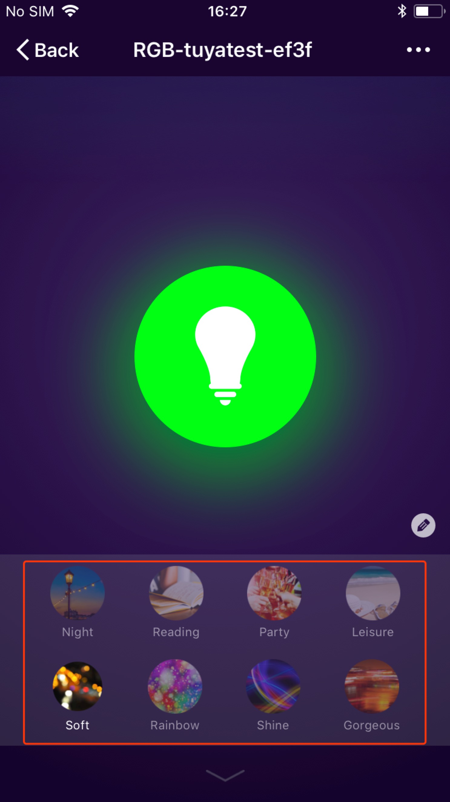
After RGB colored indicator is on, you will see four operation button on the bottom of App interface. You can conduct any operation and enjoy cell phone control. We have prepared several operation examples for you.
- Adding development in compatible mode
You can also add the development board in compatible mode. Click “Add Device” in the App and then click “Compatible Mode” in the upper right corner to enter the adding process. Please follow the App instructions for specific steps. Refer to the Manual of Tuya app for details.
Commencement of Development of Smart Hardware Products
With the previous experience, you may have a basic understanding on Tuya app. Next, you can start your journal on developing smart hardware products.
Register an account
Register an accout of Tuya Developer Platform. Enter a phone number and password for registration or login.
Creating a product
The specific way to create a product can be viewed: Device Intelligentize in 5 Minutes
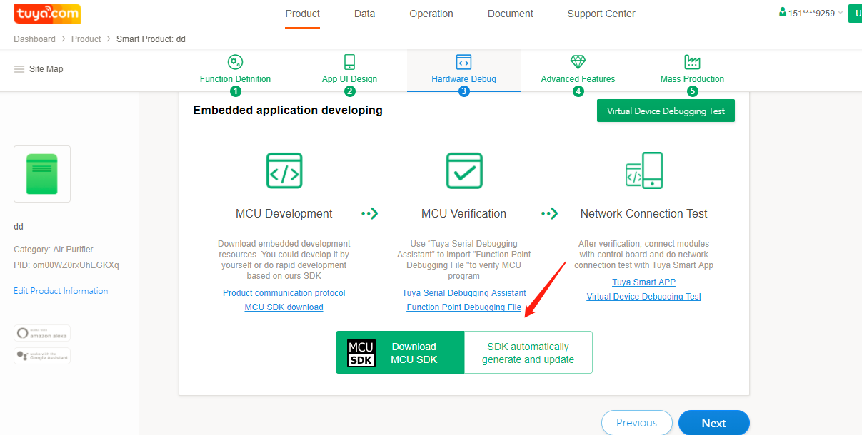
Downloading MCU Communication Protocol and SDK
This is an MCU program generated automatically from the product’s function datapoint according to Tuya Serial Port Communication Protocol. MCU engineers can develop programs quickly on this basis.
For specific development instructions, please refer to Tuya’s document center:
- Instructions for MCU SDK (Wi-Fi)
- Instructions for MCU SDK (Zigbee)
- Instructions for MCU SDK (Bluetooth Low Energy (LE))
- Instructions for serial port debugging tools
MCU Programing
Congratulations! You can program the embedded programs, and start your smart hardware development.
After the program is completed, please program the MCU firmware as described below.
Module Firmware Programing for STM32 and TYWE1S
Note: if STM32 chip is to be developed based on the Demo program provided by Tuya Smart, you can refer to the following methods to program or upgrade STM32 firmware.
STM32 Using Serial Port Downloader
The development board has CP2012 USB-to-serial-port chip. Therefore, you can use the USB cable to connect to the computer to upgrade STM32 program. ST’s Flash_Loader is required. “Flash_Loader_Demonstrator” is available in our dataset, and users can download and install it on their computers. Downloading link
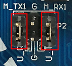
Step 1: connect RX and TX at the serial port connection end of the MCU and USB-to-serial-port chip through the short-circuit block, as shown in the figure below; and then supply power to the development board with the USB cable. This step has been done when the development board is produced.
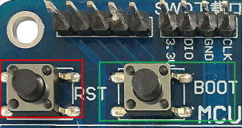
Step 2: press the BOOT button of MCU first, and then press the RESET button of MCU; release the RESET button, and then release the BOOT button. Those buttons are shown in the figure below.
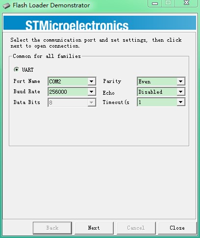
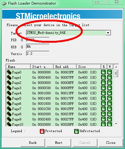
Step 3: open ST’s official serial port programing software, "Falsh Loader” (it can be downloaded online or on ST’s official website. The configuration is as follows. Click Computer-Management-Device Manager to view the serial port number. The baud rate can be selected by yourselves. Other parameters are as shown in the figure (left) below. Then, click Next to go to the interface of the programing mode, as shown in the figure (right) below.
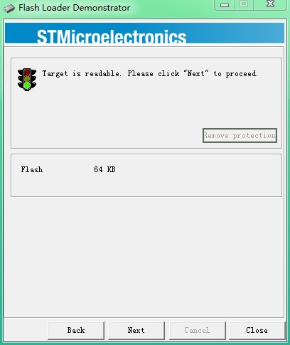
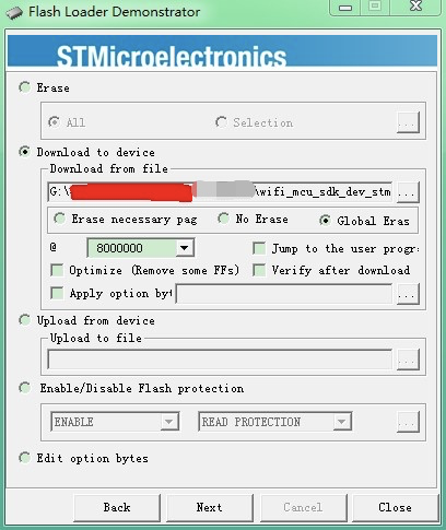
In case of any failure, please repeat the second step. Next, select HEX or BIN file, as shown in the figure (right) below, select Download to device, select the firmware (Global Erase), and click Next.
At this time, you can perform the serial port upgrade and verification. The interfaces in the process and after the completion are as follows:
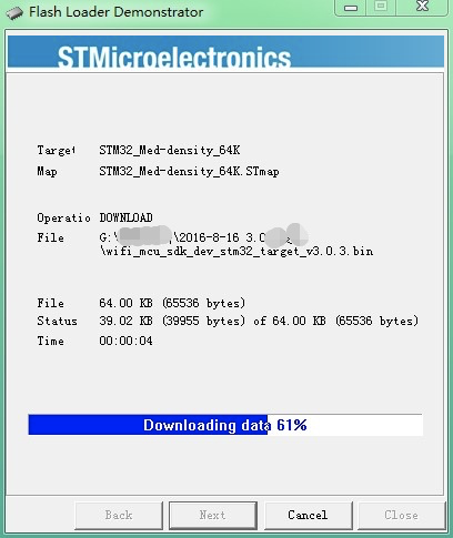
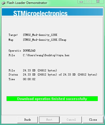
Click “Close” to close the Flash Loader, and then press the RESET button of MCU to run the new program.
STM32 Using ST-Link Downloader
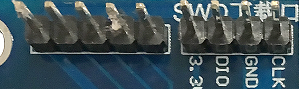
The ST-link interface of STM32 MCU is reserved on the development board. If available, the ST-link interface can be used to program and debug the MCU program. The ST-Link downloader shall be connected according to the silk-screen indication of the development board. The location of the development board is shown in the figure below.
ST-link-related downloading settings can be conducted in Keil or other compilers for quick program downloading and debugging.
STM32 Using J-Link Downloader
The J-link interface of STM32 MCU is also reserved on the development board. If available, the J-link interface can be used to program and debug the MCU program. The circuit shall be connected according to the silk-screen indication of the development board. The location of the development board is shown in the figure below.
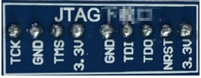
J-link-related downloading settings can be conducted in Keil or other compilers for quick program downloading and debugging.
Serial Port Downloader for Wi-Fi Module
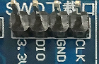
The firmware programming and information printing ports for Wi-Fi modules are reserved on the development board, including the stand-alone interfaces for Module TYWE1S and ESP-12F, as shown in the figure below.
Since the module shall be activated and authorized before delivery for functioning well, the improper firmware programming behavior for the Wi-Fi module will affect the well functioning. Therefore, please use it with caution. If the firmware upgrade is required, please contact the technical support department of Tuya Smart.
Conclusions
OK! All the functions of TYDE3.0 have been introduced, and we have experienced the most basic development process of the IoT application. We believe everyone can get started quickly. For more information, please visit Tuya’s Development document center.
In case of any improper remarks, please provide feedback for us. Thx!
Is this page helpful?
YesFeedbackIs this page helpful?
YesFeedback


