MCU Integration Protocol for Wi-Fi Lock
The MCU embedded in the Wi-Fi lock communicates with Tuya’s Wi-Fi module using the serial protocol developed by Tuya. The serial communication is shown below.

Serial communication convention
- Baud: 115200
- Data bit: 8
- Parity check: none
- Stop bit: 1
- Data flow control: none
- MCU: microcontroller unit. Your MCU communicates with Tuya’s Wi-Fi modules through the serial protocol. This protocol is designed to enable full-duplex communication between the device and the server.
Frame format description
| Field | Bytes | Description |
|---|---|---|
| Header | 2 | It is fixed to 0x55aa. |
| Version | 1 | It is used for updates and extensions. |
| Command | 1 | Frame type |
| Data length | 2 | Big-endian |
| Data | N | None |
| Checksum | 1 | Start from the header, add up all the bytes, and then divide the sum by 256 to get the remainder. |
Note:
-
All data greater than one byte is transmitted in big-endian format.
-
All sample data in the protocol is in hexadecimal format.
-
The Wi-Fi module sends packets and waits for response packets. If no response is received within 500 ms, the unanswered packets will be retransmitted twice.
-
Generally, one command is sent by one party and received by the other party synchronously. That is, one party sends a command and waits for a response from the other party. If the sender does not receive a correct response packet within a specified time period, the transmission times out, as shown in the following figure.
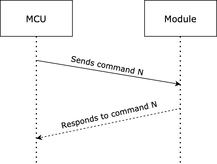
Note: For specific communication modes, see the section Protocol list in this topic.
-
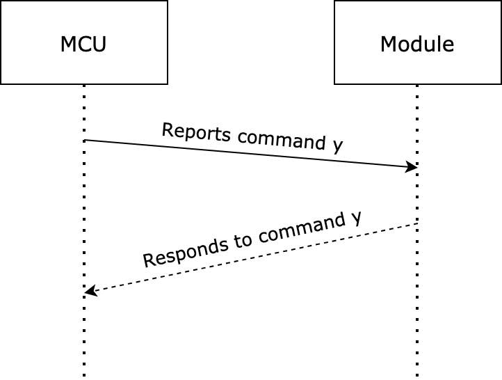
The MCU reports status synchronously. Assume that the MCU reports a command
y. The data transmission is as follows.The MCU reports data:
Data point (DP) format (aka status data unit)
| Field | Length | Description |
|---|---|---|
| dp_id | 1 | The command code of a DP. |
| dp_type | 1 | The data type of a DP. |
| dp_data_len | 2 | The data length of a DP. |
| dp_data_value | dp_data_len | The data of a DP. For more information, see Wi-Fi Lock DP Reference. |
Data type
| dp_type | Value | Length (byte) | Description |
|---|---|---|---|
| raw | 0 | 1 to 255 | The raw data type. For more information, see Wi-Fi Lock DP Reference. |
| Bool | 1 | 1 | The Boolean value. |
| Value | 2 | 4 | The integer value. |
| String | 3 | 0 to 255 | The string. It might be empty. |
| Enum | 4 | 1 | The enum value. |
Things to note
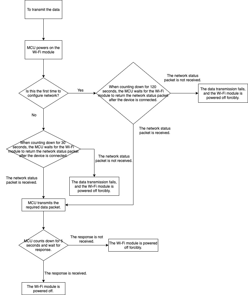
- This protocol applies to devices that use Wi-Fi modules and cannot use an external power supply. During the development of MCU programs, power-off management is especially important. You can try to reduce the power-on time of the Wi-Fi module to reduce the power consumption of the device. The process of data uploading is provided in this topic. You can implement the required functions and adjust relevant control logic as needed.
- In many cases, a device works properly when the Wi-Fi network is not enabled. Therefore, users might disable the Wi-Fi network when they do not need it. To reduce unnecessary power consumption in this case, you can design a physical button or an option on the device. When users press this button or enable this option, the MCU powers on the Wi-Fi module for data transmission only when data changes.
Integrate with non-keep-alive Wi-Fi locks
Color annotation: general interfaces, extension interfaces.
| Frame | Command | Standard locks | Locks with image upload feature | ||||||||||||||||||||||||||||||||||||||||||||||||||||||||||||||||||||||||||||||||||||||||||||||||||||||||||||||||||||||||||||||||||||||||||||||||||||||||||||||||||||||||||||||||||||||||||||||||||||||||||||||||||||||||||||||||||||||||||||||||||||||||||||||||||||||||||||||||||||||||||||||||||||||||||||||||||||||||||||||||||||||||||||||||||||||||||||||||||||||||||||||||||||||||||||||||||||||||||||||||||||||||||||||||||||||||||||||||||||||||||||||||||||||||||||||||||||||||||||||||||||||||||||||||||||||||||||||||||||||||||||||||||||||||||||||||||||||||||||||||||||||||||||||||||||||||||||||||||||||||||||||||||||||||||||||||||||||||||||||||||||||||||||||||||||||||||||||||||||||||||||||||||||||||||||||||||||||||||||||||||||||||||||||||||||||||||||||||||||||||||||||||||||||||||||||||||||||||||||||||||||||||||||||||||||||||||||||||||||||||||||||||||||||||||||||||||||||||||||||||||||||||||||||||||||||||||||||||||||||||||||||||||||||||||||||||||||||||||||||||||||||||||||||||||||||||||||||||||||
|---|---|---|---|---|---|---|---|---|---|---|---|---|---|---|---|---|---|---|---|---|---|---|---|---|---|---|---|---|---|---|---|---|---|---|---|---|---|---|---|---|---|---|---|---|---|---|---|---|---|---|---|---|---|---|---|---|---|---|---|---|---|---|---|---|---|---|---|---|---|---|---|---|---|---|---|---|---|---|---|---|---|---|---|---|---|---|---|---|---|---|---|---|---|---|---|---|---|---|---|---|---|---|---|---|---|---|---|---|---|---|---|---|---|---|---|---|---|---|---|---|---|---|---|---|---|---|---|---|---|---|---|---|---|---|---|---|---|---|---|---|---|---|---|---|---|---|---|---|---|---|---|---|---|---|---|---|---|---|---|---|---|---|---|---|---|---|---|---|---|---|---|---|---|---|---|---|---|---|---|---|---|---|---|---|---|---|---|---|---|---|---|---|---|---|---|---|---|---|---|---|---|---|---|---|---|---|---|---|---|---|---|---|---|---|---|---|---|---|---|---|---|---|---|---|---|---|---|---|---|---|---|---|---|---|---|---|---|---|---|---|---|---|---|---|---|---|---|---|---|---|---|---|---|---|---|---|---|---|---|---|---|---|---|---|---|---|---|---|---|---|---|---|---|---|---|---|---|---|---|---|---|---|---|---|---|---|---|---|---|---|---|---|---|---|---|---|---|---|---|---|---|---|---|---|---|---|---|---|---|---|---|---|---|---|---|---|---|---|---|---|---|---|---|---|---|---|---|---|---|---|---|---|---|---|---|---|---|---|---|---|---|---|---|---|---|---|---|---|---|---|---|---|---|---|---|---|---|---|---|---|---|---|---|---|---|---|---|---|---|---|---|---|---|---|---|---|---|---|---|---|---|---|---|---|---|---|---|---|---|---|---|---|---|---|---|---|---|---|---|---|---|---|---|---|---|---|---|---|---|---|---|---|---|---|---|---|---|---|---|---|---|---|---|---|---|---|---|---|---|---|---|---|---|---|---|---|---|---|---|---|---|---|---|---|---|---|---|---|---|---|---|---|---|---|---|---|---|---|---|---|---|---|---|---|---|---|---|---|---|---|---|---|---|---|---|---|---|---|---|---|---|---|---|---|---|---|---|---|---|---|---|---|---|---|---|---|---|---|---|---|---|---|---|---|---|---|---|---|---|---|---|---|---|---|---|---|---|---|---|---|---|---|---|---|---|---|---|---|---|---|---|---|---|---|---|---|---|---|---|---|---|---|---|---|---|---|---|---|---|---|---|---|---|---|---|---|---|---|---|---|---|---|---|---|---|---|---|---|---|---|---|---|---|---|---|---|---|---|---|---|---|---|---|---|---|---|---|---|---|---|---|---|---|---|---|---|---|---|---|---|---|---|---|---|---|---|---|---|---|---|---|---|---|---|---|---|---|---|---|---|---|---|---|---|---|---|---|---|---|---|---|---|---|---|---|---|---|---|---|---|---|---|---|---|---|---|---|---|---|---|---|---|---|---|---|---|---|---|---|---|---|---|---|---|---|---|---|---|---|---|---|---|---|---|---|---|---|---|---|---|---|---|---|---|---|---|---|---|---|---|---|---|---|---|---|---|---|---|---|---|---|---|---|---|---|---|---|---|---|---|---|---|---|---|---|---|---|---|---|---|---|---|---|---|---|---|---|---|---|---|---|---|---|---|---|---|---|---|---|---|---|---|---|---|---|---|---|---|---|---|---|---|---|---|---|---|---|---|---|---|---|---|---|---|---|---|---|---|---|---|---|---|---|---|---|---|---|---|---|---|---|---|---|---|---|---|---|---|---|---|---|---|---|---|---|---|---|---|---|---|---|---|---|---|---|---|---|---|---|---|---|---|---|---|---|---|---|---|---|---|---|---|---|---|---|---|---|---|---|---|---|---|---|---|---|---|---|---|---|---|---|---|---|---|---|---|---|---|---|---|---|---|---|---|---|---|---|---|---|---|---|---|---|---|---|---|---|---|---|---|---|---|---|---|---|---|---|---|---|---|---|---|---|---|---|---|---|---|---|---|---|---|---|---|---|---|---|---|---|---|---|---|---|---|---|---|---|---|---|---|---|---|---|---|---|---|---|---|---|---|---|---|---|---|---|---|---|---|---|---|---|---|---|---|---|---|---|---|---|---|---|---|---|---|---|---|---|---|---|---|---|---|---|---|---|---|---|---|---|---|---|---|---|---|---|---|---|---|---|---|---|---|---|---|---|---|---|---|---|---|---|---|---|---|---|---|---|---|---|---|---|---|---|---|---|---|---|---|---|
| Query product information | 0x01 | Supported | Supported | ||||||||||||||||||||||||||||||||||||||||||||||||||||||||||||||||||||||||||||||||||||||||||||||||||||||||||||||||||||||||||||||||||||||||||||||||||||||||||||||||||||||||||||||||||||||||||||||||||||||||||||||||||||||||||||||||||||||||||||||||||||||||||||||||||||||||||||||||||||||||||||||||||||||||||||||||||||||||||||||||||||||||||||||||||||||||||||||||||||||||||||||||||||||||||||||||||||||||||||||||||||||||||||||||||||||||||||||||||||||||||||||||||||||||||||||||||||||||||||||||||||||||||||||||||||||||||||||||||||||||||||||||||||||||||||||||||||||||||||||||||||||||||||||||||||||||||||||||||||||||||||||||||||||||||||||||||||||||||||||||||||||||||||||||||||||||||||||||||||||||||||||||||||||||||||||||||||||||||||||||||||||||||||||||||||||||||||||||||||||||||||||||||||||||||||||||||||||||||||||||||||||||||||||||||||||||||||||||||||||||||||||||||||||||||||||||||||||||||||||||||||||||||||||||||||||||||||||||||||||||||||||||||||||||||||||||||||||||||||||||||||||||||||||||||||||||||||||||||||
| Report network status | 0x02 | Supported | Supported | ||||||||||||||||||||||||||||||||||||||||||||||||||||||||||||||||||||||||||||||||||||||||||||||||||||||||||||||||||||||||||||||||||||||||||||||||||||||||||||||||||||||||||||||||||||||||||||||||||||||||||||||||||||||||||||||||||||||||||||||||||||||||||||||||||||||||||||||||||||||||||||||||||||||||||||||||||||||||||||||||||||||||||||||||||||||||||||||||||||||||||||||||||||||||||||||||||||||||||||||||||||||||||||||||||||||||||||||||||||||||||||||||||||||||||||||||||||||||||||||||||||||||||||||||||||||||||||||||||||||||||||||||||||||||||||||||||||||||||||||||||||||||||||||||||||||||||||||||||||||||||||||||||||||||||||||||||||||||||||||||||||||||||||||||||||||||||||||||||||||||||||||||||||||||||||||||||||||||||||||||||||||||||||||||||||||||||||||||||||||||||||||||||||||||||||||||||||||||||||||||||||||||||||||||||||||||||||||||||||||||||||||||||||||||||||||||||||||||||||||||||||||||||||||||||||||||||||||||||||||||||||||||||||||||||||||||||||||||||||||||||||||||||||||||||||||||||||||||||||
| Reset Wi-Fi connection | 0x03 | Supported | Supported | ||||||||||||||||||||||||||||||||||||||||||||||||||||||||||||||||||||||||||||||||||||||||||||||||||||||||||||||||||||||||||||||||||||||||||||||||||||||||||||||||||||||||||||||||||||||||||||||||||||||||||||||||||||||||||||||||||||||||||||||||||||||||||||||||||||||||||||||||||||||||||||||||||||||||||||||||||||||||||||||||||||||||||||||||||||||||||||||||||||||||||||||||||||||||||||||||||||||||||||||||||||||||||||||||||||||||||||||||||||||||||||||||||||||||||||||||||||||||||||||||||||||||||||||||||||||||||||||||||||||||||||||||||||||||||||||||||||||||||||||||||||||||||||||||||||||||||||||||||||||||||||||||||||||||||||||||||||||||||||||||||||||||||||||||||||||||||||||||||||||||||||||||||||||||||||||||||||||||||||||||||||||||||||||||||||||||||||||||||||||||||||||||||||||||||||||||||||||||||||||||||||||||||||||||||||||||||||||||||||||||||||||||||||||||||||||||||||||||||||||||||||||||||||||||||||||||||||||||||||||||||||||||||||||||||||||||||||||||||||||||||||||||||||||||||||||||||||||||||||
| Reset Wi-Fi connection and select pairing mode | 0x04 | Supported | Supported | ||||||||||||||||||||||||||||||||||||||||||||||||||||||||||||||||||||||||||||||||||||||||||||||||||||||||||||||||||||||||||||||||||||||||||||||||||||||||||||||||||||||||||||||||||||||||||||||||||||||||||||||||||||||||||||||||||||||||||||||||||||||||||||||||||||||||||||||||||||||||||||||||||||||||||||||||||||||||||||||||||||||||||||||||||||||||||||||||||||||||||||||||||||||||||||||||||||||||||||||||||||||||||||||||||||||||||||||||||||||||||||||||||||||||||||||||||||||||||||||||||||||||||||||||||||||||||||||||||||||||||||||||||||||||||||||||||||||||||||||||||||||||||||||||||||||||||||||||||||||||||||||||||||||||||||||||||||||||||||||||||||||||||||||||||||||||||||||||||||||||||||||||||||||||||||||||||||||||||||||||||||||||||||||||||||||||||||||||||||||||||||||||||||||||||||||||||||||||||||||||||||||||||||||||||||||||||||||||||||||||||||||||||||||||||||||||||||||||||||||||||||||||||||||||||||||||||||||||||||||||||||||||||||||||||||||||||||||||||||||||||||||||||||||||||||||||||||||||||||
| Report real-time status | 0x05 | Supported | Supported | ||||||||||||||||||||||||||||||||||||||||||||||||||||||||||||||||||||||||||||||||||||||||||||||||||||||||||||||||||||||||||||||||||||||||||||||||||||||||||||||||||||||||||||||||||||||||||||||||||||||||||||||||||||||||||||||||||||||||||||||||||||||||||||||||||||||||||||||||||||||||||||||||||||||||||||||||||||||||||||||||||||||||||||||||||||||||||||||||||||||||||||||||||||||||||||||||||||||||||||||||||||||||||||||||||||||||||||||||||||||||||||||||||||||||||||||||||||||||||||||||||||||||||||||||||||||||||||||||||||||||||||||||||||||||||||||||||||||||||||||||||||||||||||||||||||||||||||||||||||||||||||||||||||||||||||||||||||||||||||||||||||||||||||||||||||||||||||||||||||||||||||||||||||||||||||||||||||||||||||||||||||||||||||||||||||||||||||||||||||||||||||||||||||||||||||||||||||||||||||||||||||||||||||||||||||||||||||||||||||||||||||||||||||||||||||||||||||||||||||||||||||||||||||||||||||||||||||||||||||||||||||||||||||||||||||||||||||||||||||||||||||||||||||||||||||||||||||||||||||
| Report status of record type | 0x08 | Supported | Supported | ||||||||||||||||||||||||||||||||||||||||||||||||||||||||||||||||||||||||||||||||||||||||||||||||||||||||||||||||||||||||||||||||||||||||||||||||||||||||||||||||||||||||||||||||||||||||||||||||||||||||||||||||||||||||||||||||||||||||||||||||||||||||||||||||||||||||||||||||||||||||||||||||||||||||||||||||||||||||||||||||||||||||||||||||||||||||||||||||||||||||||||||||||||||||||||||||||||||||||||||||||||||||||||||||||||||||||||||||||||||||||||||||||||||||||||||||||||||||||||||||||||||||||||||||||||||||||||||||||||||||||||||||||||||||||||||||||||||||||||||||||||||||||||||||||||||||||||||||||||||||||||||||||||||||||||||||||||||||||||||||||||||||||||||||||||||||||||||||||||||||||||||||||||||||||||||||||||||||||||||||||||||||||||||||||||||||||||||||||||||||||||||||||||||||||||||||||||||||||||||||||||||||||||||||||||||||||||||||||||||||||||||||||||||||||||||||||||||||||||||||||||||||||||||||||||||||||||||||||||||||||||||||||||||||||||||||||||||||||||||||||||||||||||||||||||||||||||||||||||
| Module sends commands | 0x09 | Supported | Supported | ||||||||||||||||||||||||||||||||||||||||||||||||||||||||||||||||||||||||||||||||||||||||||||||||||||||||||||||||||||||||||||||||||||||||||||||||||||||||||||||||||||||||||||||||||||||||||||||||||||||||||||||||||||||||||||||||||||||||||||||||||||||||||||||||||||||||||||||||||||||||||||||||||||||||||||||||||||||||||||||||||||||||||||||||||||||||||||||||||||||||||||||||||||||||||||||||||||||||||||||||||||||||||||||||||||||||||||||||||||||||||||||||||||||||||||||||||||||||||||||||||||||||||||||||||||||||||||||||||||||||||||||||||||||||||||||||||||||||||||||||||||||||||||||||||||||||||||||||||||||||||||||||||||||||||||||||||||||||||||||||||||||||||||||||||||||||||||||||||||||||||||||||||||||||||||||||||||||||||||||||||||||||||||||||||||||||||||||||||||||||||||||||||||||||||||||||||||||||||||||||||||||||||||||||||||||||||||||||||||||||||||||||||||||||||||||||||||||||||||||||||||||||||||||||||||||||||||||||||||||||||||||||||||||||||||||||||||||||||||||||||||||||||||||||||||||||||||||||||||
| Get local time | 0x06 | Supported | Supported | ||||||||||||||||||||||||||||||||||||||||||||||||||||||||||||||||||||||||||||||||||||||||||||||||||||||||||||||||||||||||||||||||||||||||||||||||||||||||||||||||||||||||||||||||||||||||||||||||||||||||||||||||||||||||||||||||||||||||||||||||||||||||||||||||||||||||||||||||||||||||||||||||||||||||||||||||||||||||||||||||||||||||||||||||||||||||||||||||||||||||||||||||||||||||||||||||||||||||||||||||||||||||||||||||||||||||||||||||||||||||||||||||||||||||||||||||||||||||||||||||||||||||||||||||||||||||||||||||||||||||||||||||||||||||||||||||||||||||||||||||||||||||||||||||||||||||||||||||||||||||||||||||||||||||||||||||||||||||||||||||||||||||||||||||||||||||||||||||||||||||||||||||||||||||||||||||||||||||||||||||||||||||||||||||||||||||||||||||||||||||||||||||||||||||||||||||||||||||||||||||||||||||||||||||||||||||||||||||||||||||||||||||||||||||||||||||||||||||||||||||||||||||||||||||||||||||||||||||||||||||||||||||||||||||||||||||||||||||||||||||||||||||||||||||||||||||||||||||||||
| Wi-Fi functional test | 0x07 | Supported but 0xF0 is recommended |
Supported but 0xF0 is recommended |
||||||||||||||||||||||||||||||||||||||||||||||||||||||||||||||||||||||||||||||||||||||||||||||||||||||||||||||||||||||||||||||||||||||||||||||||||||||||||||||||||||||||||||||||||||||||||||||||||||||||||||||||||||||||||||||||||||||||||||||||||||||||||||||||||||||||||||||||||||||||||||||||||||||||||||||||||||||||||||||||||||||||||||||||||||||||||||||||||||||||||||||||||||||||||||||||||||||||||||||||||||||||||||||||||||||||||||||||||||||||||||||||||||||||||||||||||||||||||||||||||||||||||||||||||||||||||||||||||||||||||||||||||||||||||||||||||||||||||||||||||||||||||||||||||||||||||||||||||||||||||||||||||||||||||||||||||||||||||||||||||||||||||||||||||||||||||||||||||||||||||||||||||||||||||||||||||||||||||||||||||||||||||||||||||||||||||||||||||||||||||||||||||||||||||||||||||||||||||||||||||||||||||||||||||||||||||||||||||||||||||||||||||||||||||||||||||||||||||||||||||||||||||||||||||||||||||||||||||||||||||||||||||||||||||||||||||||||||||||||||||||||||||||||||||||||||||||||||||||
| Request Wi-Fi module firmware update | 0x0a | Supported but inapplicable to WBR1 and WBR3 |
Supported but 0x21 is recommended | ||||||||||||||||||||||||||||||||||||||||||||||||||||||||||||||||||||||||||||||||||||||||||||||||||||||||||||||||||||||||||||||||||||||||||||||||||||||||||||||||||||||||||||||||||||||||||||||||||||||||||||||||||||||||||||||||||||||||||||||||||||||||||||||||||||||||||||||||||||||||||||||||||||||||||||||||||||||||||||||||||||||||||||||||||||||||||||||||||||||||||||||||||||||||||||||||||||||||||||||||||||||||||||||||||||||||||||||||||||||||||||||||||||||||||||||||||||||||||||||||||||||||||||||||||||||||||||||||||||||||||||||||||||||||||||||||||||||||||||||||||||||||||||||||||||||||||||||||||||||||||||||||||||||||||||||||||||||||||||||||||||||||||||||||||||||||||||||||||||||||||||||||||||||||||||||||||||||||||||||||||||||||||||||||||||||||||||||||||||||||||||||||||||||||||||||||||||||||||||||||||||||||||||||||||||||||||||||||||||||||||||||||||||||||||||||||||||||||||||||||||||||||||||||||||||||||||||||||||||||||||||||||||||||||||||||||||||||||||||||||||||||||||||||||||||||||||||||||||||
| Request MCU firmware update | 0x0c | Supported but inapplicable to WBR1 and WBR3 |
Supported but 0x21 is recommended | ||||||||||||||||||||||||||||||||||||||||||||||||||||||||||||||||||||||||||||||||||||||||||||||||||||||||||||||||||||||||||||||||||||||||||||||||||||||||||||||||||||||||||||||||||||||||||||||||||||||||||||||||||||||||||||||||||||||||||||||||||||||||||||||||||||||||||||||||||||||||||||||||||||||||||||||||||||||||||||||||||||||||||||||||||||||||||||||||||||||||||||||||||||||||||||||||||||||||||||||||||||||||||||||||||||||||||||||||||||||||||||||||||||||||||||||||||||||||||||||||||||||||||||||||||||||||||||||||||||||||||||||||||||||||||||||||||||||||||||||||||||||||||||||||||||||||||||||||||||||||||||||||||||||||||||||||||||||||||||||||||||||||||||||||||||||||||||||||||||||||||||||||||||||||||||||||||||||||||||||||||||||||||||||||||||||||||||||||||||||||||||||||||||||||||||||||||||||||||||||||||||||||||||||||||||||||||||||||||||||||||||||||||||||||||||||||||||||||||||||||||||||||||||||||||||||||||||||||||||||||||||||||||||||||||||||||||||||||||||||||||||||||||||||||||||||||||||||||||||
| Start update | 0x0d | Supported | Supported | ||||||||||||||||||||||||||||||||||||||||||||||||||||||||||||||||||||||||||||||||||||||||||||||||||||||||||||||||||||||||||||||||||||||||||||||||||||||||||||||||||||||||||||||||||||||||||||||||||||||||||||||||||||||||||||||||||||||||||||||||||||||||||||||||||||||||||||||||||||||||||||||||||||||||||||||||||||||||||||||||||||||||||||||||||||||||||||||||||||||||||||||||||||||||||||||||||||||||||||||||||||||||||||||||||||||||||||||||||||||||||||||||||||||||||||||||||||||||||||||||||||||||||||||||||||||||||||||||||||||||||||||||||||||||||||||||||||||||||||||||||||||||||||||||||||||||||||||||||||||||||||||||||||||||||||||||||||||||||||||||||||||||||||||||||||||||||||||||||||||||||||||||||||||||||||||||||||||||||||||||||||||||||||||||||||||||||||||||||||||||||||||||||||||||||||||||||||||||||||||||||||||||||||||||||||||||||||||||||||||||||||||||||||||||||||||||||||||||||||||||||||||||||||||||||||||||||||||||||||||||||||||||||||||||||||||||||||||||||||||||||||||||||||||||||||||||||||||||||||
| Transmit update package | 0x0e | Supported | Supported | ||||||||||||||||||||||||||||||||||||||||||||||||||||||||||||||||||||||||||||||||||||||||||||||||||||||||||||||||||||||||||||||||||||||||||||||||||||||||||||||||||||||||||||||||||||||||||||||||||||||||||||||||||||||||||||||||||||||||||||||||||||||||||||||||||||||||||||||||||||||||||||||||||||||||||||||||||||||||||||||||||||||||||||||||||||||||||||||||||||||||||||||||||||||||||||||||||||||||||||||||||||||||||||||||||||||||||||||||||||||||||||||||||||||||||||||||||||||||||||||||||||||||||||||||||||||||||||||||||||||||||||||||||||||||||||||||||||||||||||||||||||||||||||||||||||||||||||||||||||||||||||||||||||||||||||||||||||||||||||||||||||||||||||||||||||||||||||||||||||||||||||||||||||||||||||||||||||||||||||||||||||||||||||||||||||||||||||||||||||||||||||||||||||||||||||||||||||||||||||||||||||||||||||||||||||||||||||||||||||||||||||||||||||||||||||||||||||||||||||||||||||||||||||||||||||||||||||||||||||||||||||||||||||||||||||||||||||||||||||||||||||||||||||||||||||||||||||||||||||
| Query signal strength of the connected router | 0x0b | Supported | Supported | ||||||||||||||||||||||||||||||||||||||||||||||||||||||||||||||||||||||||||||||||||||||||||||||||||||||||||||||||||||||||||||||||||||||||||||||||||||||||||||||||||||||||||||||||||||||||||||||||||||||||||||||||||||||||||||||||||||||||||||||||||||||||||||||||||||||||||||||||||||||||||||||||||||||||||||||||||||||||||||||||||||||||||||||||||||||||||||||||||||||||||||||||||||||||||||||||||||||||||||||||||||||||||||||||||||||||||||||||||||||||||||||||||||||||||||||||||||||||||||||||||||||||||||||||||||||||||||||||||||||||||||||||||||||||||||||||||||||||||||||||||||||||||||||||||||||||||||||||||||||||||||||||||||||||||||||||||||||||||||||||||||||||||||||||||||||||||||||||||||||||||||||||||||||||||||||||||||||||||||||||||||||||||||||||||||||||||||||||||||||||||||||||||||||||||||||||||||||||||||||||||||||||||||||||||||||||||||||||||||||||||||||||||||||||||||||||||||||||||||||||||||||||||||||||||||||||||||||||||||||||||||||||||||||||||||||||||||||||||||||||||||||||||||||||||||||||||||||||||||
| Request temporary password from the cloud (single password only) | 0x11 | Supported | Supported | ||||||||||||||||||||||||||||||||||||||||||||||||||||||||||||||||||||||||||||||||||||||||||||||||||||||||||||||||||||||||||||||||||||||||||||||||||||||||||||||||||||||||||||||||||||||||||||||||||||||||||||||||||||||||||||||||||||||||||||||||||||||||||||||||||||||||||||||||||||||||||||||||||||||||||||||||||||||||||||||||||||||||||||||||||||||||||||||||||||||||||||||||||||||||||||||||||||||||||||||||||||||||||||||||||||||||||||||||||||||||||||||||||||||||||||||||||||||||||||||||||||||||||||||||||||||||||||||||||||||||||||||||||||||||||||||||||||||||||||||||||||||||||||||||||||||||||||||||||||||||||||||||||||||||||||||||||||||||||||||||||||||||||||||||||||||||||||||||||||||||||||||||||||||||||||||||||||||||||||||||||||||||||||||||||||||||||||||||||||||||||||||||||||||||||||||||||||||||||||||||||||||||||||||||||||||||||||||||||||||||||||||||||||||||||||||||||||||||||||||||||||||||||||||||||||||||||||||||||||||||||||||||||||||||||||||||||||||||||||||||||||||||||||||||||||||||||||||||||||
| Verify dynamic password | 0x12 | Supported | Supported | ||||||||||||||||||||||||||||||||||||||||||||||||||||||||||||||||||||||||||||||||||||||||||||||||||||||||||||||||||||||||||||||||||||||||||||||||||||||||||||||||||||||||||||||||||||||||||||||||||||||||||||||||||||||||||||||||||||||||||||||||||||||||||||||||||||||||||||||||||||||||||||||||||||||||||||||||||||||||||||||||||||||||||||||||||||||||||||||||||||||||||||||||||||||||||||||||||||||||||||||||||||||||||||||||||||||||||||||||||||||||||||||||||||||||||||||||||||||||||||||||||||||||||||||||||||||||||||||||||||||||||||||||||||||||||||||||||||||||||||||||||||||||||||||||||||||||||||||||||||||||||||||||||||||||||||||||||||||||||||||||||||||||||||||||||||||||||||||||||||||||||||||||||||||||||||||||||||||||||||||||||||||||||||||||||||||||||||||||||||||||||||||||||||||||||||||||||||||||||||||||||||||||||||||||||||||||||||||||||||||||||||||||||||||||||||||||||||||||||||||||||||||||||||||||||||||||||||||||||||||||||||||||||||||||||||||||||||||||||||||||||||||||||||||||||||||||||||||||||||
| Request temporary password from the cloud (multiple passwords) | 0x13 | Supported | Supported | ||||||||||||||||||||||||||||||||||||||||||||||||||||||||||||||||||||||||||||||||||||||||||||||||||||||||||||||||||||||||||||||||||||||||||||||||||||||||||||||||||||||||||||||||||||||||||||||||||||||||||||||||||||||||||||||||||||||||||||||||||||||||||||||||||||||||||||||||||||||||||||||||||||||||||||||||||||||||||||||||||||||||||||||||||||||||||||||||||||||||||||||||||||||||||||||||||||||||||||||||||||||||||||||||||||||||||||||||||||||||||||||||||||||||||||||||||||||||||||||||||||||||||||||||||||||||||||||||||||||||||||||||||||||||||||||||||||||||||||||||||||||||||||||||||||||||||||||||||||||||||||||||||||||||||||||||||||||||||||||||||||||||||||||||||||||||||||||||||||||||||||||||||||||||||||||||||||||||||||||||||||||||||||||||||||||||||||||||||||||||||||||||||||||||||||||||||||||||||||||||||||||||||||||||||||||||||||||||||||||||||||||||||||||||||||||||||||||||||||||||||||||||||||||||||||||||||||||||||||||||||||||||||||||||||||||||||||||||||||||||||||||||||||||||||||||||||||||||||||
| Request temporary password from cloud (with schedule list) | 0x14 | Supported | Supported | ||||||||||||||||||||||||||||||||||||||||||||||||||||||||||||||||||||||||||||||||||||||||||||||||||||||||||||||||||||||||||||||||||||||||||||||||||||||||||||||||||||||||||||||||||||||||||||||||||||||||||||||||||||||||||||||||||||||||||||||||||||||||||||||||||||||||||||||||||||||||||||||||||||||||||||||||||||||||||||||||||||||||||||||||||||||||||||||||||||||||||||||||||||||||||||||||||||||||||||||||||||||||||||||||||||||||||||||||||||||||||||||||||||||||||||||||||||||||||||||||||||||||||||||||||||||||||||||||||||||||||||||||||||||||||||||||||||||||||||||||||||||||||||||||||||||||||||||||||||||||||||||||||||||||||||||||||||||||||||||||||||||||||||||||||||||||||||||||||||||||||||||||||||||||||||||||||||||||||||||||||||||||||||||||||||||||||||||||||||||||||||||||||||||||||||||||||||||||||||||||||||||||||||||||||||||||||||||||||||||||||||||||||||||||||||||||||||||||||||||||||||||||||||||||||||||||||||||||||||||||||||||||||||||||||||||||||||||||||||||||||||||||||||||||||||||||||||||||||||
| Get DP cache command | 0x15 | Supported | Supported | ||||||||||||||||||||||||||||||||||||||||||||||||||||||||||||||||||||||||||||||||||||||||||||||||||||||||||||||||||||||||||||||||||||||||||||||||||||||||||||||||||||||||||||||||||||||||||||||||||||||||||||||||||||||||||||||||||||||||||||||||||||||||||||||||||||||||||||||||||||||||||||||||||||||||||||||||||||||||||||||||||||||||||||||||||||||||||||||||||||||||||||||||||||||||||||||||||||||||||||||||||||||||||||||||||||||||||||||||||||||||||||||||||||||||||||||||||||||||||||||||||||||||||||||||||||||||||||||||||||||||||||||||||||||||||||||||||||||||||||||||||||||||||||||||||||||||||||||||||||||||||||||||||||||||||||||||||||||||||||||||||||||||||||||||||||||||||||||||||||||||||||||||||||||||||||||||||||||||||||||||||||||||||||||||||||||||||||||||||||||||||||||||||||||||||||||||||||||||||||||||||||||||||||||||||||||||||||||||||||||||||||||||||||||||||||||||||||||||||||||||||||||||||||||||||||||||||||||||||||||||||||||||||||||||||||||||||||||||||||||||||||||||||||||||||||||||||||||||||||
| Offline dynamic password | 0x16 | Supported | Supported | ||||||||||||||||||||||||||||||||||||||||||||||||||||||||||||||||||||||||||||||||||||||||||||||||||||||||||||||||||||||||||||||||||||||||||||||||||||||||||||||||||||||||||||||||||||||||||||||||||||||||||||||||||||||||||||||||||||||||||||||||||||||||||||||||||||||||||||||||||||||||||||||||||||||||||||||||||||||||||||||||||||||||||||||||||||||||||||||||||||||||||||||||||||||||||||||||||||||||||||||||||||||||||||||||||||||||||||||||||||||||||||||||||||||||||||||||||||||||||||||||||||||||||||||||||||||||||||||||||||||||||||||||||||||||||||||||||||||||||||||||||||||||||||||||||||||||||||||||||||||||||||||||||||||||||||||||||||||||||||||||||||||||||||||||||||||||||||||||||||||||||||||||||||||||||||||||||||||||||||||||||||||||||||||||||||||||||||||||||||||||||||||||||||||||||||||||||||||||||||||||||||||||||||||||||||||||||||||||||||||||||||||||||||||||||||||||||||||||||||||||||||||||||||||||||||||||||||||||||||||||||||||||||||||||||||||||||||||||||||||||||||||||||||||||||||||||||||||||||||
| Report serial number of MCU | 0x17 | Supported | Supported | ||||||||||||||||||||||||||||||||||||||||||||||||||||||||||||||||||||||||||||||||||||||||||||||||||||||||||||||||||||||||||||||||||||||||||||||||||||||||||||||||||||||||||||||||||||||||||||||||||||||||||||||||||||||||||||||||||||||||||||||||||||||||||||||||||||||||||||||||||||||||||||||||||||||||||||||||||||||||||||||||||||||||||||||||||||||||||||||||||||||||||||||||||||||||||||||||||||||||||||||||||||||||||||||||||||||||||||||||||||||||||||||||||||||||||||||||||||||||||||||||||||||||||||||||||||||||||||||||||||||||||||||||||||||||||||||||||||||||||||||||||||||||||||||||||||||||||||||||||||||||||||||||||||||||||||||||||||||||||||||||||||||||||||||||||||||||||||||||||||||||||||||||||||||||||||||||||||||||||||||||||||||||||||||||||||||||||||||||||||||||||||||||||||||||||||||||||||||||||||||||||||||||||||||||||||||||||||||||||||||||||||||||||||||||||||||||||||||||||||||||||||||||||||||||||||||||||||||||||||||||||||||||||||||||||||||||||||||||||||||||||||||||||||||||||||||||||||||||||||
| Notify status of module reset | 0x25 | Supported | Supported | ||||||||||||||||||||||||||||||||||||||||||||||||||||||||||||||||||||||||||||||||||||||||||||||||||||||||||||||||||||||||||||||||||||||||||||||||||||||||||||||||||||||||||||||||||||||||||||||||||||||||||||||||||||||||||||||||||||||||||||||||||||||||||||||||||||||||||||||||||||||||||||||||||||||||||||||||||||||||||||||||||||||||||||||||||||||||||||||||||||||||||||||||||||||||||||||||||||||||||||||||||||||||||||||||||||||||||||||||||||||||||||||||||||||||||||||||||||||||||||||||||||||||||||||||||||||||||||||||||||||||||||||||||||||||||||||||||||||||||||||||||||||||||||||||||||||||||||||||||||||||||||||||||||||||||||||||||||||||||||||||||||||||||||||||||||||||||||||||||||||||||||||||||||||||||||||||||||||||||||||||||||||||||||||||||||||||||||||||||||||||||||||||||||||||||||||||||||||||||||||||||||||||||||||||||||||||||||||||||||||||||||||||||||||||||||||||||||||||||||||||||||||||||||||||||||||||||||||||||||||||||||||||||||||||||||||||||||||||||||||||||||||||||||||||||||||||||||||||||||
| Positional notation | 0x1c | Supported | Supported | ||||||||||||||||||||||||||||||||||||||||||||||||||||||||||||||||||||||||||||||||||||||||||||||||||||||||||||||||||||||||||||||||||||||||||||||||||||||||||||||||||||||||||||||||||||||||||||||||||||||||||||||||||||||||||||||||||||||||||||||||||||||||||||||||||||||||||||||||||||||||||||||||||||||||||||||||||||||||||||||||||||||||||||||||||||||||||||||||||||||||||||||||||||||||||||||||||||||||||||||||||||||||||||||||||||||||||||||||||||||||||||||||||||||||||||||||||||||||||||||||||||||||||||||||||||||||||||||||||||||||||||||||||||||||||||||||||||||||||||||||||||||||||||||||||||||||||||||||||||||||||||||||||||||||||||||||||||||||||||||||||||||||||||||||||||||||||||||||||||||||||||||||||||||||||||||||||||||||||||||||||||||||||||||||||||||||||||||||||||||||||||||||||||||||||||||||||||||||||||||||||||||||||||||||||||||||||||||||||||||||||||||||||||||||||||||||||||||||||||||||||||||||||||||||||||||||||||||||||||||||||||||||||||||||||||||||||||||||||||||||||||||||||||||||||||||||||||||||||||
| Wi-Fi functional test | 0xF0 | Supported | Supported | ||||||||||||||||||||||||||||||||||||||||||||||||||||||||||||||||||||||||||||||||||||||||||||||||||||||||||||||||||||||||||||||||||||||||||||||||||||||||||||||||||||||||||||||||||||||||||||||||||||||||||||||||||||||||||||||||||||||||||||||||||||||||||||||||||||||||||||||||||||||||||||||||||||||||||||||||||||||||||||||||||||||||||||||||||||||||||||||||||||||||||||||||||||||||||||||||||||||||||||||||||||||||||||||||||||||||||||||||||||||||||||||||||||||||||||||||||||||||||||||||||||||||||||||||||||||||||||||||||||||||||||||||||||||||||||||||||||||||||||||||||||||||||||||||||||||||||||||||||||||||||||||||||||||||||||||||||||||||||||||||||||||||||||||||||||||||||||||||||||||||||||||||||||||||||||||||||||||||||||||||||||||||||||||||||||||||||||||||||||||||||||||||||||||||||||||||||||||||||||||||||||||||||||||||||||||||||||||||||||||||||||||||||||||||||||||||||||||||||||||||||||||||||||||||||||||||||||||||||||||||||||||||||||||||||||||||||||||||||||||||||||||||||||||||||||||||||||||||||||
| Automatic updates | 0x21 | Supported | Supported | ||||||||||||||||||||||||||||||||||||||||||||||||||||||||||||||||||||||||||||||||||||||||||||||||||||||||||||||||||||||||||||||||||||||||||||||||||||||||||||||||||||||||||||||||||||||||||||||||||||||||||||||||||||||||||||||||||||||||||||||||||||||||||||||||||||||||||||||||||||||||||||||||||||||||||||||||||||||||||||||||||||||||||||||||||||||||||||||||||||||||||||||||||||||||||||||||||||||||||||||||||||||||||||||||||||||||||||||||||||||||||||||||||||||||||||||||||||||||||||||||||||||||||||||||||||||||||||||||||||||||||||||||||||||||||||||||||||||||||||||||||||||||||||||||||||||||||||||||||||||||||||||||||||||||||||||||||||||||||||||||||||||||||||||||||||||||||||||||||||||||||||||||||||||||||||||||||||||||||||||||||||||||||||||||||||||||||||||||||||||||||||||||||||||||||||||||||||||||||||||||||||||||||||||||||||||||||||||||||||||||||||||||||||||||||||||||||||||||||||||||||||||||||||||||||||||||||||||||||||||||||||||||||||||||||||||||||||||||||||||||||||||||||||||||||||||||||||||||||||
| Event notification | 0x60 | Not supported | Supported | ||||||||||||||||||||||||||||||||||||||||||||||||||||||||||||||||||||||||||||||||||||||||||||||||||||||||||||||||||||||||||||||||||||||||||||||||||||||||||||||||||||||||||||||||||||||||||||||||||||||||||||||||||||||||||||||||||||||||||||||||||||||||||||||||||||||||||||||||||||||||||||||||||||||||||||||||||||||||||||||||||||||||||||||||||||||||||||||||||||||||||||||||||||||||||||||||||||||||||||||||||||||||||||||||||||||||||||||||||||||||||||||||||||||||||||||||||||||||||||||||||||||||||||||||||||||||||||||||||||||||||||||||||||||||||||||||||||||||||||||||||||||||||||||||||||||||||||||||||||||||||||||||||||||||||||||||||||||||||||||||||||||||||||||||||||||||||||||||||||||||||||||||||||||||||||||||||||||||||||||||||||||||||||||||||||||||||||||||||||||||||||||||||||||||||||||||||||||||||||||||||||||||||||||||||||||||||||||||||||||||||||||||||||||||||||||||||||||||||||||||||||||||||||||||||||||||||||||||||||||||||||||||||||||||||||||||||||||||||||||||||||||||||||||||||||||||||||||||||||
| Image upload | 0x61 | Not supported | Supported | ||||||||||||||||||||||||||||||||||||||||||||||||||||||||||||||||||||||||||||||||||||||||||||||||||||||||||||||||||||||||||||||||||||||||||||||||||||||||||||||||||||||||||||||||||||||||||||||||||||||||||||||||||||||||||||||||||||||||||||||||||||||||||||||||||||||||||||||||||||||||||||||||||||||||||||||||||||||||||||||||||||||||||||||||||||||||||||||||||||||||||||||||||||||||||||||||||||||||||||||||||||||||||||||||||||||||||||||||||||||||||||||||||||||||||||||||||||||||||||||||||||||||||||||||||||||||||||||||||||||||||||||||||||||||||||||||||||||||||||||||||||||||||||||||||||||||||||||||||||||||||||||||||||||||||||||||||||||||||||||||||||||||||||||||||||||||||||||||||||||||||||||||||||||||||||||||||||||||||||||||||||||||||||||||||||||||||||||||||||||||||||||||||||||||||||||||||||||||||||||||||||||||||||||||||||||||||||||||||||||||||||||||||||||||||||||||||||||||||||||||||||||||||||||||||||||||||||||||||||||||||||||||||||||||||||||||||||||||||||||||||||||||||||||||||||||||||||||||||||
| Image upload result | 0x62 | Not supported | Supported | ||||||||||||||||||||||||||||||||||||||||||||||||||||||||||||||||||||||||||||||||||||||||||||||||||||||||||||||||||||||||||||||||||||||||||||||||||||||||||||||||||||||||||||||||||||||||||||||||||||||||||||||||||||||||||||||||||||||||||||||||||||||||||||||||||||||||||||||||||||||||||||||||||||||||||||||||||||||||||||||||||||||||||||||||||||||||||||||||||||||||||||||||||||||||||||||||||||||||||||||||||||||||||||||||||||||||||||||||||||||||||||||||||||||||||||||||||||||||||||||||||||||||||||||||||||||||||||||||||||||||||||||||||||||||||||||||||||||||||||||||||||||||||||||||||||||||||||||||||||||||||||||||||||||||||||||||||||||||||||||||||||||||||||||||||||||||||||||||||||||||||||||||||||||||||||||||||||||||||||||||||||||||||||||||||||||||||||||||||||||||||||||||||||||||||||||||||||||||||||||||||||||||||||||||||||||||||||||||||||||||||||||||||||||||||||||||||||||||||||||||||||||||||||||||||||||||||||||||||||||||||||||||||||||||||||||||||||||||||||||||||||||||||||||||||||||||||||||||||||
| Image upload status | 0x63 | Not supported | Supported | ||||||||||||||||||||||||||||||||||||||||||||||||||||||||||||||||||||||||||||||||||||||||||||||||||||||||||||||||||||||||||||||||||||||||||||||||||||||||||||||||||||||||||||||||||||||||||||||||||||||||||||||||||||||||||||||||||||||||||||||||||||||||||||||||||||||||||||||||||||||||||||||||||||||||||||||||||||||||||||||||||||||||||||||||||||||||||||||||||||||||||||||||||||||||||||||||||||||||||||||||||||||||||||||||||||||||||||||||||||||||||||||||||||||||||||||||||||||||||||||||||||||||||||||||||||||||||||||||||||||||||||||||||||||||||||||||||||||||||||||||||||||||||||||||||||||||||||||||||||||||||||||||||||||||||||||||||||||||||||||||||||||||||||||||||||||||||||||||||||||||||||||||||||||||||||||||||||||||||||||||||||||||||||||||||||||||||||||||||||||||||||||||||||||||||||||||||||||||||||||||||||||||||||||||||||||||||||||||||||||||||||||||||||||||||||||||||||||||||||||||||||||||||||||||||||||||||||||||||||||||||||||||||||||||||||||||||||||||||||||||||||||||||||||||||||||||||||||||||||
| Trigger capturing | 0x64 | Not supported | Supported | ||||||||||||||||||||||||||||||||||||||||||||||||||||||||||||||||||||||||||||||||||||||||||||||||||||||||||||||||||||||||||||||||||||||||||||||||||||||||||||||||||||||||||||||||||||||||||||||||||||||||||||||||||||||||||||||||||||||||||||||||||||||||||||||||||||||||||||||||||||||||||||||||||||||||||||||||||||||||||||||||||||||||||||||||||||||||||||||||||||||||||||||||||||||||||||||||||||||||||||||||||||||||||||||||||||||||||||||||||||||||||||||||||||||||||||||||||||||||||||||||||||||||||||||||||||||||||||||||||||||||||||||||||||||||||||||||||||||||||||||||||||||||||||||||||||||||||||||||||||||||||||||||||||||||||||||||||||||||||||||||||||||||||||||||||||||||||||||||||||||||||||||||||||||||||||||||||||||||||||||||||||||||||||||||||||||||||||||||||||||||||||||||||||||||||||||||||||||||||||||||||||||||||||||||||||||||||||||||||||||||||||||||||||||||||||||||||||||||||||||||||||||||||||||||||||||||||||||||||||||||||||||||||||||||||||||||||||||||||||||||||||||||||||||||||||||||||||||||||||
| Capturing result | 0x62 | Not supported | Supported | ||||||||||||||||||||||||||||||||||||||||||||||||||||||||||||||||||||||||||||||||||||||||||||||||||||||||||||||||||||||||||||||||||||||||||||||||||||||||||||||||||||||||||||||||||||||||||||||||||||||||||||||||||||||||||||||||||||||||||||||||||||||||||||||||||||||||||||||||||||||||||||||||||||||||||||||||||||||||||||||||||||||||||||||||||||||||||||||||||||||||||||||||||||||||||||||||||||||||||||||||||||||||||||||||||||||||||||||||||||||||||||||||||||||||||||||||||||||||||||||||||||||||||||||||||||||||||||||||||||||||||||||||||||||||||||||||||||||||||||||||||||||||||||||||||||||||||||||||||||||||||||||||||||||||||||||||||||||||||||||||||||||||||||||||||||||||||||||||||||||||||||||||||||||||||||||||||||||||||||||||||||||||||||||||||||||||||||||||||||||||||||||||||||||||||||||||||||||||||||||||||||||||||||||||||||||||||||||||||||||||||||||||||||||||||||||||||||||||||||||||||||||||||||||||||||||||||||||||||||||||||||||||||||||||||||||||||||||||||||||||||||||||||||||||||||||||||||||||||||
| Configure graphics RAM | 0x66 | Not supported | Supported | ||||||||||||||||||||||||||||||||||||||||||||||||||||||||||||||||||||||||||||||||||||||||||||||||||||||||||||||||||||||||||||||||||||||||||||||||||||||||||||||||||||||||||||||||||||||||||||||||||||||||||||||||||||||||||||||||||||||||||||||||||||||||||||||||||||||||||||||||||||||||||||||||||||||||||||||||||||||||||||||||||||||||||||||||||||||||||||||||||||||||||||||||||||||||||||||||||||||||||||||||||||||||||||||||||||||||||||||||||||||||||||||||||||||||||||||||||||||||||||||||||||||||||||||||||||||||||||||||||||||||||||||||||||||||||||||||||||||||||||||||||||||||||||||||||||||||||||||||||||||||||||||||||||||||||||||||||||||||||||||||||||||||||||||||||||||||||||||||||||||||||||||||||||||||||||||||||||||||||||||||||||||||||||||||||||||||||||||||||||||||||||||||||||||||||||||||||||||||||||||||||||||||||||||||||||||||||||||||||||||||||||||||||||||||||||||||||||||||||||||||||||||||||||||||||||||||||||||||||||||||||||||||||||||||||||||||||||||||||||||||||||||||||||||||||||||||||||||||||||
| Configure graphics parameters | 0x65 | Not supported | Supported | ||||||||||||||||||||||||||||||||||||||||||||||||||||||||||||||||||||||||||||||||||||||||||||||||||||||||||||||||||||||||||||||||||||||||||||||||||||||||||||||||||||||||||||||||||||||||||||||||||||||||||||||||||||||||||||||||||||||||||||||||||||||||||||||||||||||||||||||||||||||||||||||||||||||||||||||||||||||||||||||||||||||||||||||||||||||||||||||||||||||||||||||||||||||||||||||||||||||||||||||||||||||||||||||||||||||||||||||||||||||||||||||||||||||||||||||||||||||||||||||||||||||||||||||||||||||||||||||||||||||||||||||||||||||||||||||||||||||||||||||||||||||||||||||||||||||||||||||||||||||||||||||||||||||||||||||||||||||||||||||||||||||||||||||||||||||||||||||||||||||||||||||||||||||||||||||||||||||||||||||||||||||||||||||||||||||||||||||||||||||||||||||||||||||||||||||||||||||||||||||||||||||||||||||||||||||||||||||||||||||||||||||||||||||||||||||||||||||||||||||||||||||||||||||||||||||||||||||||||||||||||||||||||||||||||||||||||||||||||||||||||||||||||||||||||||||||||||||||||||
| Field | Bytes | Description |
|---|---|---|
| Header | 2 | 0x55aa |
| Version | 1 | 0x00 |
| Command | 1 | 0x01 |
| Data length | 2 | 0x0000 |
| Data | 0 | None |
| Checksum | 1 | Start from the header, add up all the bytes, and then divide the sum by 256 to get the remainder. |
The module sends the following command:
55 aa 00 01 00 00 00
The MCU returns the following command:
| Field | Bytes | Description |
|---|---|---|
| Header | 2 | 0x55aa |
| Version | 1 | 0x00 |
| Command | 1 | 0x01 |
| Data length | 2 | N |
| Data | N | {"p":”vHXEcqntLpkAlOsy”, "v":”1.0.0”, ”n”:0, ”cap”:0} |
| Checksum | 1 | Start from the header, add up all the bytes, and then divide the sum by 256 to get the remainder. |
p represents the PID.
vHXEcqntLpkAlOsy is the PID of the product created on the Tuya Developer Platform.
v represents the MCU version.
1.0.0 is the version number.
n is an optional field. It represents the pairing mode.
-
Switch between easy connect (EZ) mode and access point (AP) mode. This is the default pairing mode.
The pairing mode is switched between EZ mode and AP mode. The mode will be switched to the other one after a reset.
-
Support AP mode only (Not available)
Users can pair devices only through AP mode.
caprepresents capabilities of a device:bit0indicates whether the device supports capturing.
0: Capturing and image upload are not supported.
1: Capturing and image upload are supported.bit1indicates which communication protocol is used for image transmission. This capability is available whenbit0is1.
0: UART
1: SPIbit2indicates whether the device supports the cellular network. (Not available)
0: not support
1: supportbit3indicates whether the device supports notification of module reset.
0: not support
1: support
Note: Set the reserved bit to
0.For example,
{"p":”vHXEcqntLpkAlOsy”,"v":”1.0.0”,”n”:0,”cap”:11}The MCU returns the following command:
55 AA 00 01 00 2D 7B 22 70 22 3A 22 66 66 78 70 67 6A 71 64 6E 71 61 6C 6D 6B 64 6B 22 2C 22 76 22 3A 22 31 2E 30 2E 30 22 2C 22 63 61 70 22 3A 31 31 7D 95
Report network status
| Network status | Description | Status value |
|---|---|---|
| Status 1 | Pair a device in EZ mode. | 0x00 |
| Status 2 | Pair a device in AP mode. | 0x01 |
| Status 3 | The Wi-Fi network has been set up but not connected to the router. | 0x02 |
| Status 4 | The Wi-Fi network has been set up and connected to the router. | 0x03 |
| Status 5 | The network connects to the router and the cloud. | 0x04 |
| Status 6 | The Wi-Fi device is in low power mode. | 0x05 |
| EZ mode and AP mode coexist. | 0x06 (not supported currently) |
- When the Wi-Fi network status changes, the module sends the current status to the MCU.
- The MCU can get the current network status to update the app on current status 1 and status 2.
- In principle, you need to implement these two pairing modes. Router compatibility issues might occur when a device is paired in EZ mode. In this case, AP mode can be used to pair the device.
- Before pairing, the powered-on module runs in low power mode by default. After the MCU sends a command to reset Wi-Fi, the module enters pairing mode.
- When a device is removed from the app, the module enters the low power mode. After the MCU sends a command to reset Wi-Fi, the module enters pairing mode.
- After the module enters pairing mode, if it fails to connect to the router within 10 seconds and is powered off, it can resume the status before powered off when it is powered on again.
Note: After the MCU receives status 5, you must not immediately power off the module. You can specify a delay time of at least three seconds before power-off. Otherwise, the module might not work properly.
The module sends the following command:
| Field | Bytes | Description |
|---|---|---|
| Header | 2 | 0x55aa |
| Version | 1 | 0x00 |
| Command | 1 | 0x02 |
| Data length | 2 | 0x0001 |
| Data | 1 | Indicates Wi-Fi connection status: 0x00: status 1 0x01: status 2 0x02: status 3 0x03: status 4 0x04: status 5 0x05: status 6 0x06: status 7 |
| Checksum | 1 | Start from the header, add up all the bytes, and then divide the sum by 256 to get the remainder. |
The module sends the following command:
55 aa 00 02 00 01 04 06 (indicates the network connects to the router and the cloud.)
The MCU returns the following command:
| Field | Bytes | Description |
|---|---|---|
| Header | 2 | 0x55aa |
| Version | 1 | 0x00 |
| Command | 1 | 0x02 |
| Data length | 2 | 0x0000 |
| Data | 0 | None |
| Checksum | 1 | Start from the header, add up all the bytes, and then divide the sum by 256 to get the remainder. |
The MCU returns the following command:
55 aa 00 02 00 00 01
Reset Wi-Fi connection
-
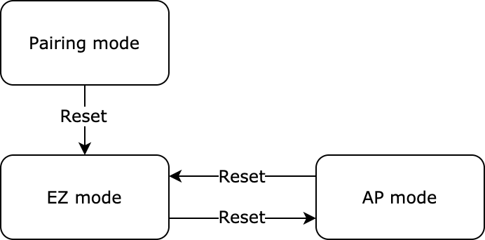
If EZ mode and AP mode coexist, the module still works in this coexistence mode after reset.
-
If only AP mode is used, the module still works in this AP-only mode after reset.
-
If AP mode and EZ mode are switched alternately, the pairing mode is changed after reset, as shown below:
The MCU sends the following command:
| Field | Bytes | Description |
|---|---|---|
| Header | 2 | 0x55aa |
| Version | 1 | 0x00 |
| Command | 1 | 0x03 |
| Data length | 2 | 0x0000 |
| Data | 0 | None |
| Checksum | 1 | Start from the header, add up all the bytes, and then divide the sum by 256 to get the remainder. |
The MCU sends the following command:
55 aa 00 03 00 00 02
The module returns the following command:
| Field | Bytes | Description |
|---|---|---|
| Header | 2 | 0x55aa |
| Version | 1 | 0x00 |
| Command | 1 | 0x03 |
| Data length | 2 | 0x0000 |
| Data | 0 | None |
| Checksum | 1 | Start from the header, add up all the bytes, and then divide the sum by 256 to get the remainder. |
The module returns the following command:
55 aa 00 03 00 00 02
Reset Wi-Fi connection (select pairing mode)
- This reset command works only when you specify EZ mode and AP mode for Query product information.
- Compared to Reset Wi-Fi connection, this frame enables the MCU to select the pairing mode after a Wi-Fi reset.
- You can implement this protocol as needed.
The MCU sends the following command:
| Field | Bytes | Description |
|---|---|---|
| Header | 2 | 0x55aa |
| Version | 1 | 0x00 |
| Command | 1 | 0x04 |
| Data length | 2 | 0x0001 |
| Data | 1 | 0x00: Enter EZ mode. 0x01: Enter AP mode. |
| Checksum | 1 | Start from the header, add up all the bytes, and then divide the sum by 256 to get the remainder. |
The MCU sends a command to let the module enter AP mode:
55 aa 00 04 00 01 01 05
The module returns the following command:
| Field | Bytes | Description |
|---|---|---|
| Header | 2 | 0x55aa |
| Version | 1 | 0x00 |
| Command | 1 | 0x04 |
| Data length | 2 | 0x0000 |
| Data | 0 | None |
| Checksum | 1 | Start from the header, add up all the bytes, and then divide the sum by 256 to get the remainder. |
The module returns the following command:
55 aa 00 04 00 00 03
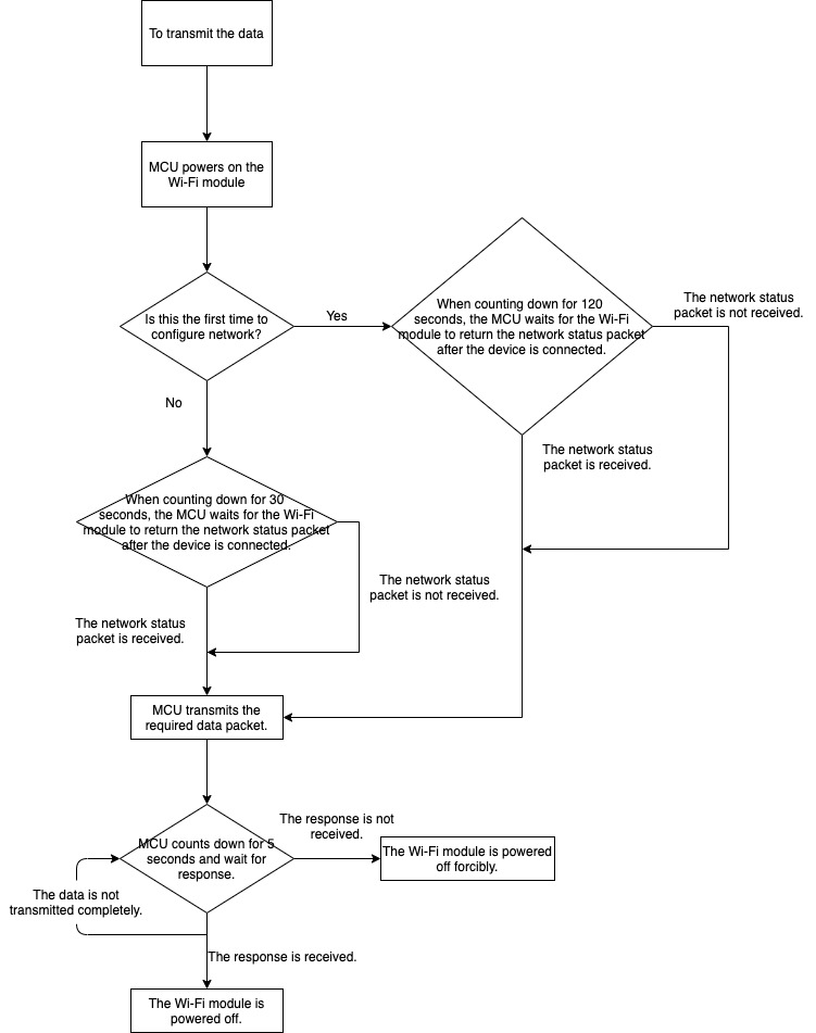
Report real-time status
This command enables devices that require real-time pushes, such as alarms, to make quick status reporting.
Note: This protocol allows the MCU to report real-time status data.
-
Status data is directly sent to the cloud, which requires the device to be connected to the cloud. Otherwise, data transmission will fail.
-
This is a synchronous command. The MCU reports data and waits five seconds for a response from the module.
-
When the MCU receives the network status packet indicating the module has connected to the server, it will send the status data packet. The module does not cache the stranded data. Therefore, if the MCU does not receive a network status packet within eight seconds, it will power off the module.
-
You can set packets to be transmitted in single or multiple data units. For more information about data packets, see the examples in this section.
The operation process is as follows:
The MCU sends the following command:
| Field | Bytes | Description |
|---|---|---|
| Header | 2 | 0x55aa |
| Version | 1 | 0x00 |
| Command | 1 | 0x05 |
| Data length | 2 | It depends on types and the number of status data units. |
| Data | N | Single or multiple status data units. |
| Checksum | 1 | Start from the header, add up all the bytes, and then divide the sum by 256 to get the remainder. |
The module returns the following command:
| Field | Bytes | Description |
|---|---|---|
| Header | 2 | 0x55aa |
| Version | 1 | 0x00 |
| Command | 1 | 0x05 |
| Data length | 2 | 0x0001 |
| Data | 1 | 0x00: success. 0x01: failure. |
| Checksum | 1 | Start from the header, add up all the bytes, and then divide the sum by 256 to get the remainder. |
Report a single status data unit
The data point (DP) 109 is a Boolean variable, and its value is 1.
55 aa 00 05 00 05 6d 01 00 01 01 79
Report multiple status data units
The data point (DP) 109 is a Boolean variable, and its value is 1.
The DP 102 is a string variable, and its value is 201804121507. The value is transferred in ASCII mode.
55 aa 00 05 00 15 6d 01 00 01 01 66 03 00 0c 32 30 31 38 30 34 31 32 31 35 30 37 5d
Report status of record type
For the door lock, the status data of multiple DPs is processed as one piece of record in the server. In case of transient network failure, this command can store data that failed to be reported. The time used in the reported data is the local time.
This command allows the MCU to send a piece of record-type data that includes multiple DPs to the Wi-Fi module. If the device is disconnected from the network when the data is being reported, the module will store this data locally and send it when the server is connected.
-
Each time when a stranded record is reported successfully, the module returns
0x01through the command0x09. The MCU can determine whether to power off the module based on the returned data. -
If the network works fine, the module can connect to the server within about four seconds after power-on. When status data is generated, the MCU will wait for the network status packet specified in Report network status. If the MCU does not receive the packet after waiting for more than six seconds, it still sends data to the module and waits for the data reporting result.
-
The maximum length of the data section for reporting one record (multiple data units of status) is 80 bytes. The actual length varies depending on the DP data. If the data section exceeds the maximum length and the network is unavailable, the Wi-Fi module returns a message indicating failed reporting.
-
The module can store a maximum of 20 historical records. When the limit is reached, the newest record will overwrite the oldest one.
-
When the module successfully reports a record, or writes stranded data to the flash memory due to network failure, it returns
0x00indicating successful reporting. When the network works fine, each time the module successfully reports one of the stranded records, it returns0x01. In other cases, it returns0x02to indicate failed reporting. -
The time data is to ensure that the record data reflects the actual events when the device is disconnected. If you use the time when the record data arrives at the server, the time of a stranded record will be inconsistent with the time when the event actually occurs. Therefore, when a device is paired for the first time, if the network works fine, you can get the time data through the protocol. This way, when a record carries the device time, the device time will prevail.
-
Due to the time zone and daylight saving time (DST), the device time is treated accordingly. For the device without a screen to display the current time, it can get the Greenwich Mean Time (GMT) based on the protocol. Therefore, GMT is used in reporting time-related status data. For the device with a screen to display the current time, it can get the local time based on the protocol. The local time is calculated by applying an offset based on the time zone and DST. It is used in reporting time-related status data.
The operation process is as follows:
The MCU sends the following command:
| Field | Bytes | Description |
|---|---|---|
| Header | 2 | 0x55aa |
| Version | 1 | 0x00 |
| Command | 1 | 0x08 |
| Data length | 2 | It depends on types and the number of status data units. |
| Data | 7 | The data length is 7 bytes. Data[0]: indicates whether the local time flag is valid. 0: The local time flag is invalid and time data is not processed. 1: The local time flag is valid and time data is represented in local time. 2: The local time flag is valid and time data is represented in GMT. Data[1]: indicates the year. For example, 0x00 indicates the year 2000. Data[2]: indicates the month, ranging from 1 to 12. Data[3]: indicates the day, ranging from 1 to 31. Data[4]: indicates the hour, ranging from 0 to 23. Data[5]: indicates the minute, ranging from 0 to 59. Data[6]: indicates the second, ranging from 0 to 59. |
| - | N | For more information about single or multiple data units of status, see Status data unit. |
| Checksum | 1 | Start from the header, add up all the bytes, and then divide the sum by 256 to get the remainder. |
The module returns the following command:
| Field | Bytes | Description |
|---|---|---|
| Header | 2 | 0x55aa |
| Version | 1 | 0x00 |
| Command | 1 | 0x08 |
| Data length | 2 | 0x0001 |
| Data | 1 | 0x00: Reporting succeeded. 0x01: Reporting succeeded, but there is still stranded data. 0x02: Reporting failed. |
| Checksum | 1 | Start from the header, add up all the bytes, and then divide the sum by 256 to get the remainder. |
Examples of packet transmission are shown as follows.
-
Report a single status data unit
The DP 109 is a Boolean variable, and its value is
1.-
The server time prevails:
55 aa 00 08 00 0c 00 12 04 13 0d 04 14 6d 01 00 01 01 d1 -
The local time prevails, for example, 13:03:29 April 19, 2018:
55 aa 00 08 00 0c 01 12 04 13 0d 03 1d 6d 01 00 01 01 da -
The GMT prevails, for example, 05:03:29 April 19, 2018:
55 aa 00 08 00 0c 02 12 04 13 05 03 1d 6d 01 00 01 01 d3
-
-
Report multiple status data units
The DP 109 is a Boolean variable, and its value is
1.The DP 102 is a string variable, and its value is
201804121507. The value is transferred in ASCII mode.-
The server time prevails:
55 aa 00 08 00 1c 00 12 04 13 0d 06 04 *6d 01 00 01 01* *66 03 00 0c 32 30 31 38 30 34 31 32 31 35 30 37* a7 -
The local time prevails, for example, 13:03:29 April 19, 2018:
55 aa 00 08 00 1c 01 12 04 13 0d 08 2e 6d 01 00 01 01 66 03 00 0c 32 30 31 38 30 34 31 32 31 35 30 37 d4 -
The GMT prevails, for example, 05:03:29 April 19, 2018:
55 aa 00 08 00 1c 02 12 04 13 05 08 2e 6d 01 00 01 01 66 03 00 0c 32 30 31 38 30 34 31 32 31 35 30 37 cd
-
-
Combined unlocking methods
A single packet transmits the status data of DPs used in combined unlocking methods.
For example, unlock a door with a password and fingerprint.
55 aa 00 08 00 17 00 13 02 0D 06 33 03(Unlock with password)02 02 00 04 00 00 00 01(Unlock with fingerprint)01 02 00 04 00 00 00 05 91
Module sends commands
The module sends commands to the MCU in an asynchronous way. The MCU acknowledges receipt of a command and executes a specific operation. Then, it sends status data of changed DPs to the module.
The module sends the following command:
| Field | Bytes | Description |
|---|---|---|
| Header | 2 | 0x55aa |
| Version | 1 | 0x00 |
| Command | 1 | 0x09 |
| Data length | 2 | Depends on the type and number of command data units. |
| Data | N | Status data units |
| Checksum | 1 | Start from the header, add up all the bytes, and then divide the sum by 256 to get the remainder. |
The module sends a command: The DP 3 of the device switch is a Boolean variable, and its value 1 can turn on the device.
55 aa 00 09 0005 *03 01 00* *01 01* 13
The MCU returns the following command:
| Field | Bytes | Description |
|---|---|---|
| Header | 2 | 0x55aa |
| Version | 1 | 0x00 |
| Command | 1 | 0x09 |
| Data length | 2 | 0x0000 |
| Data | 0 | None |
| Checksum | 1 | Start from the header, add up all the bytes, and then divide the sum by 256 to get the remainder. |
The MCU acknowledges receipt of the message:
55 aa 03 09 00 00 08
Get local time
- When the MCU receives the packet indicating the module is connected to the server, it sends a packet to get the local time.
- The request might fail due to poor network connectivity. For time-dependent devices such as door locks, if the local time is not accurate, the request will fail. Set an interval of three seconds to ensure the time data can be obtained successfully.
- Every time the module is powered on, it cannot get the time data until it is connected to the server and synchronizes time with the server.
The MCU sends the following command:
| Field | Bytes | Description |
|---|---|---|
| Header | 2 | 0x55aa |
| Version | 1 | 0x00 |
| Command | 1 | 0x06 |
| Data length | 2 | 0x0000 |
| Data | 0 | None |
| Checksum | 1 | Start from the header, add up all the bytes, and then divide the sum by 256 to get the remainder. |
The MCU gets the local time:
55 aa 00 06 00 00 05
The module returns the following command:
| Field | Bytes | Description |
|---|---|---|
| Header | 2 | 0x55aa |
| Version | 1 | 0x00 |
| Command | 1 | 0x06 |
| Data length | 2 | 0x0008 |
| Data | Data | The data length is 8 bytes. Data[0]: indicates whether the local time is obtained successfully. 0: failure. 1: success. Data[1]: indicates the year. For example, 0x00 indicates the year 2000. Data[2]: indicates the month, ranging from 1 to 12. Data[3]: indicates the day, ranging from 1 to 31. Data[4]: indicates the hour, ranging from 0 to 23. Data[5]: indicates the minute, ranging from 0 to 59. Data[6]: indicates the second, ranging from 0 to 59. Data[7]: indicates the week, ranging from 1 to 7. 1 indicates Monday. |
| Checksum | 1 | Start from the header, add up all the bytes, and then divide the sum by 256 to get the remainder. |
The module returns the local time:
55 aa 00 06 00 08 01 12 09 11 10 09 05 01 59
The preceding example indicates the local time of 16:09:05, September 17, 2018, Monday.
- If the device is activated in mainland China, the local time is Beijing time (GMT+08:00).
- If the device is activated in other countries or regions, the local time is the time zone in which the device is located.
Get the GMT
-
GMT is independent of the time zone and DST. If the door lock has a dynamic password function without displaying the local time, it only needs to implement GMT and report data in GMT through the record-type reporting channel.
-
If the door lock has a dynamic password function and displays the local time, the device needs to implement GMT and time zone offset. The displayed local time is calculated by adding the time zone offset to the GMT. Report data in GMT through the record-type reporting channel.
-
Every time the module is powered on, it cannot get the time data until it is connected to the server and synchronizes time with the server.
The MCU sends the following command:
| Field | Bytes | Description |
|---|---|---|
| Header | 2 | 0x55aa |
| Version | 1 | 0x00 |
| Command | 1 | 0x10 |
| Data length | 2 | 0x0000 |
| Data | 0 | None |
| Checksum | 1 | Start from the header, add up all the bytes, and then divide the sum by 256 to get the remainder. |
The MCU gets the GMT:
55 aa 00 10 00 00 0F
The module returns the following command:
| Field | Bytes | Description |
|---|---|---|
| Header | 2 | 0x55aa |
| Version | 1 | 0x00 |
| Command | 1 | 0x10 |
| Data length | 2 | 0x0008 |
| Data | 8 | The data length is 8 bytes. Data[0]: indicates whether the local time is obtained successfully. 0: failure. 1: success. Data[1]: indicates the year. For example, 0x00 indicates the year 2000. Data[2]: indicates the month, ranging from 1 to 12. Data[3]: indicates the day, ranging from 1 to 31. Data[4]: indicates the hour, ranging from 0 to 23. Data[5]: indicates the minute, ranging from 0 to 59. Data[6]: indicates the second, ranging from 0 to 59. Data[7]: indicates the week, ranging from 1 to 7. 1 indicates Monday. |
| Checksum | 1 | Start from the header, add up all the bytes, and then divide the sum by 256 to get the remainder. |
The module returns the GMT:
55 aa 00 10 00 08 01 12 09 11 08 15 03 01 65
The preceding example indicates the GMT of 08:21:03, September 17, 2018, Monday.
Request Wi-Fi module firmware update
- The MCU controls the Wi-Fi module on/off. It pulls firmware updates through the following command to have the module updated. The MCU determines whether to power off the Wi-Fi module according to the return packet from the Wi-Fi module. When the MCU sends the
0x0acommand but receives no response within five seconds, it powers off the Wi-Fi module. If the Wi-Fi module returns a packet indicating the firmware update is in progress, the MCU will give it a 60-second timeout period. If the MCU does not receive a packet indicating a successful update after the timeout period, it will power off the Wi-Fi module.
The MCU sends the following command:
| Field | Bytes | Description |
|---|---|---|
| Header | 2 | 0x55aa |
| Version | 1 | 0x00 |
| Command | 1 | 0x0a |
| Data length | 2 | 0x0000 |
| Data | 0 | None |
| Checksum | 1 | Start from the header, add up all the bytes, and then divide the sum by 256 to get the remainder. |
The MCU requests a Wi-Fi firmware update:
55 aa 00 0a 00 00 09
The module returns the following command:
| Field | Bytes | Description |
|---|---|---|
| Header | 2 | 0x55aa |
| Version | 1 | 0x00 |
| Command | 1 | 0x0a |
| Data length | 2 | 0x0001 |
| Data | 1 | 0x00: Check for updates. The Wi-Fi module cannot be powered off. 0x01: Firmware is up to date. The Wi-Fi module is powered off. 0x02: Update is in progress. The Wi-Fi module cannot be powered off. 0x03: Update succeeded. The Wi-Fi module is powered off. 0x04: Update failed. The Wi-Fi module is powered off. |
| Checksum | 1 | Start from the header, add up all the bytes, and then divide the sum by 256 to get the remainder. |
The module returns the following update status:
55 aa 00 0a 00 01 00 0a indicates the update package is returned.
55 aa 00 0a 00 01 01 0b indicates the firmware is up to date.
Request MCU firmware update
- The MCU receives a message from the module indicating the firmware update is completed. This indicates all the MCU updates have been pulled from the server and transmitted through the serial port.
After the MCU receives the complete updates, the module sends a query for the update information. The MCU returns product information and the latest version number that should be consistent with the one recorded in the server. - The size of the firmware updates follows that specified on the Tuya Developer Platform.
- You need to set the update method as automatic updates on the Tuya Developer Platform.
The MCU sends the following command:
| Field | Bytes | Description |
|---|---|---|
| Header | 2 | 0x55aa |
| Version | 1 | 0x00 |
| Command | 1 | 0x0c |
| Data length | 2 | 0x0000 |
| Data | 0 | None |
| Checksum | 1 | Start from the header, add up all the bytes, and then divide the sum by 256 to get the remainder. |
The MCU requests MCU firmware update:
55 aa 00 0c 00 00 0b
The module returns the following command:
| Field | Bytes | Description |
|---|---|---|
| Header | 2 | 0x55aa |
| Version | 1 | 0x00 |
| Command | 1 | 0x0c |
| Data length | 2 | 0x0001 |
| Data | 1 | 0x00: Check for updates. The Wi-Fi module cannot be powered off. 0x01: Firmware is up to date. The Wi-Fi module is powered off. 0x02: Update is in progress. The Wi-Fi module cannot be powered off. 0x03: Update succeeded. The Wi-Fi module is powered off. 0x04: Update failed. The Wi-Fi module is powered off. |
| Checksum | 1 | Start from the header, add up all the bytes, and then divide the sum by 256 to get the remainder. |
The module returns the following update status:
55 aa 00 0c 00 01 00 0c indicates the update package is returned.
55 aa 00 0c 00 01 01 0d indicates the firmware is up to date.
Start update
- When the MCU triggers the Wi-Fi module to update the MCU firmware, and the server has the latest applicable MCU firmware, the module will return the size of the update package.
- The MCU can return the required size of a single packet. If the size is not specified, it defaults to 256 bytes.
The module sends the following command:
| Field | Bytes | Description |
|---|---|---|
| Header | 2 | 0x55aa |
| Version | 1 | 0x00 |
| Command | 1 | 0x0d |
| Data length | 2 | 0x0004 |
| Data | 4 | The size of the update package. The data type is an unsigned integer, and the data is stored in big-endian format. |
| Checksum | 1 | Start from the header, add up all the bytes, and then divide the sum by 256 to get the remainder. |
The module sends the size of the update package:
55 aa 00 0d 00 04 00 00 68 00 78: the size of the update package is 26624 bytes, namely 26 KB.
The MCU returns the following command:
| Field | Bytes | Description |
|---|---|---|
| Header | 2 | 0x55aa |
| Version | 1 | 0x00 |
| Command | 1 | 0x0d |
| Data length | 2 | 0x0000 |
| Data | 0 | None |
| Checksum | 1 | Start from the header, add up all the bytes, and then divide the sum by 256 to get the remainder. |
The MCU sends ACK message:
55 aa 00 0a 00 01 00 0a indicates the single packet is 256 bytes.
Transmit update package
-
The data format of update package transmission: packet offset (unsigned short) + packet data.
-
If the MCU receives the frame with a data length equal to 4 bytes and the packet offset is equal to or greater than the size of firmware, the transmission ends.
The module sends the following command:
| Field | Bytes | Description |
|---|---|---|
| Header | 2 | 0x55aa |
| Version | 1 | 0x00 |
| Command | 1 | 0x0e |
| Data length | 2 | The sum of 0x0004 and the packet length. |
| Data | N | The first four bytes are fixed as packet offset, and the latter bytes are the packet data. |
| Checksum | 1 | Start from the header, add up all the bytes, and then divide the sum by 256 to get the remainder. |
The module sends file data:
The size of the update file is 530 bytes. The MCU can skip the response to the last packet.
-
For the first packet, packet offset is
0x00000000, and packet length is 256 bytes.55aa 00 0e 0104 00000000 xx…xx XX -
For the second packet, packet offset is
0x00000100, and packet length is 256 bytes.55aa 00 0e 0104 00000100 xx…xx XX -
For the third packet, packet offset is
0x00000200, and packet length is 18 bytes.55aa 00 0e 0016 00000200 xx…xx XX -
For the last packet, packet offset is
0x00000212, and packet length is 0 bytes.55aa 00 0e 0004 00000212 xx…xx XX
The MCU returns the following command:
| Field | Bytes | Description |
|---|---|---|
| Header | 2 | 0x55aa |
| Version | 1 | 0x00 |
| Command | 1 | 0x0e |
| Data length | 2 | 0x0000 |
| Data | 0 | None |
| Checksum | 1 | Start from the header, add up all the bytes, and then divide the sum by 256 to get the remainder. |
The MCU confirms each packet:
55aa 00 0e 0000 0d
Query signal strength of the connected router
- To get the signal strength of the router, the MCU must receive the network status packet indicating the device has connected to the router. Otherwise, the command will return a failed result.
The MCU sends the following command:
| Field | Bytes | Description |
|---|---|---|
| Header | 2 | 0x55aa |
| Version | 1 | 0x00 |
| Command | 1 | 0x0b |
| Data length | 2 | 0x0000 |
| Data | 0 | None |
| Checksum | 1 | Start from the header, add up all the bytes, and then divide the sum by 256 to get the remainder. |
The MCU gets the signal strength of the connected router:
55 aa 00 0b 00 00 0a
The module returns the following command:
| Field | Bytes | Description |
|---|---|---|
| Header | 2 | 0x55aa |
| Version | 1 | 0x00 |
| Command | 1 | 0x0b |
| Data length | 2 | 0x0002 |
| Data | 2 | The data length is 2 bytes. Data[0]: 0x00 indicates failure, and 0x01 indicates success. When Data[0] is 0x01, Data[1] indicates the signal strength, ranging from 0 to 100, 0 for the weakest and 100 for the strongest. When Data[0] is 0x00, if Data[1] is 0x00, it indicates the device failed to connect to the router. |
| Checksum | 1 | Start from the header, add up all the bytes, and then divide the sum by 256 to get the remainder. |
The module returns the current signal strength of 80:
55 aa 00 0b 00 02 01 50 5D
Verify dynamic password
- The data of GMT is used to compute the current dynamic password. Therefore, GMT must be provided to the module.
- The permissions to verify dynamic passwords can be set on the app. Generating dynamic passwords requires the admin password for password comparison. Therefore, when a device requests dynamic password verification, all the admin passwords must be sent to the module.
(Not supported currently) - The data length of the packet must be at least 15 bytes, containing time data, password, and the number of admin passwords (excluding the optional admin password).
The MCU sends the following command:
| Field | Bytes | Description |
|---|---|---|
| Header | 2 | 0x55aa |
| Version | 1 | 0x00 |
| Command | 1 | 0x12 |
| Data length | 2 | 0x0006+0x08+0x01+N |
| Data | 6 | The current time in GMT, with a data length of 6 bytes. Data[0]: indicates the year. For example, 0x00 indicates the year 2000. Data[1]: indicates the month, ranging from 1 to 12. Data[2]: indicates the day, ranging from 1 to 31. Data[3]: indicates the hour, ranging from 0 to 23. Data[4]: indicates the minute, ranging from 0 to 59. Data[5]: indicates the second, ranging from 0 to 59. |
| - | 8 | The data of password entered by the user: from Data[6] to Data[13]. The data content ranges from 0 to 9, transferred in ASCII mode. |
| - | 1 | The number of admin passwords, ranging from 0 to 10. Contain the actual number of admin passwords. (This field is not supported currently, so the value defaults to 0.) |
| Checksum | 1 | Start from the header, add up all the bytes, and then divide the sum by 256 to get the remainder. |
The MCU sends a packet with two 6-byte admin passwords:
55 aa 00 12 00 1C 12 09 11 06 22 29 31 35 39 35 30 31 35 38 02 06 *35 32 31 33 31 34* 35 32 31 33 31 33 b3
The first password: 521314
The second password: 521313
The module returns the following command:
| Field | Bytes | Description |
|---|---|---|
| Header | 2 | 0x55aa |
| Version | 1 | 0x00 |
| Command | 1 | 0x12 |
| Data length | 2 | 0x0001 |
| Data | 1 | 0x00: valid password. 0x01: invalid password. 0x02: device not activated. 0x03: data length error. |
| Checksum | 1 | Start from the header, add up all the bytes, and then divide the sum by 256 to get the remainder. |
The module returns a failed verification result:
55 aa 00 12 00 01 01 13
Request temporary password from the cloud (single password only)
- The device can get the currently valid password only when a user creates a password of the current time on the app.
- This interface can only get a single temporary password. It is used for general firmware v1.0.0 and coupled with an applicable control panel. For firmware versions later than v1.0.0, the interface has been changed to the one for getting multiple temporary passwords.
The MCU sends the following command:
| Field | Bytes | Description |
|---|---|---|
| Header | 2 | 0x55aa |
| Version | 1 | 0x00 |
| Command | 1 | 0x11 |
| Data length | 2 | 0x0000 |
| Data | 0 | None |
| Checksum | 1 | Start from the header, add up all the bytes, and then divide the sum by 256 to get the remainder. |
The lock gets the currently valid temporary password:
55 aa 00 11 00 00 10
The module returns the following command:
| Field | Bytes | Description |
|---|---|---|
| Header | 2 | 0x55aa |
| Version | 1 | 0x00 |
| Command | 1 | 0x11 |
| Data length | 2 | 0x0007+N (temporary password) |
| Data | 7+N | The data length is 7+N bytes. Data[0]: indicates whether the password is obtained successfully. 0 indicates failure with a data length of one byte, and the data of password and valid time will not be transmitted in serial communication. 1 indicates success and the expiration time in GMT. Data[1]: indicates the year. For example, 0x00 indicates the year 2000. Data[2]: indicates the month, ranging from 1 to 12. Data[3]: indicates the day, ranging from 1 to 31. Data[4]: indicates the hour, ranging from 0 to 23. Data[5]: indicates the minute, ranging from 0 to 59. Data[6]: indicates the second, ranging from 0 to 59. The temporary password is transferred in ASCII mode. |
| Checksum | 1 | Start from the header, add up all the bytes, and then divide the sum by 256 to get the remainder. |
The module returns the temporary password:
55 aa 00 11 00 0d 01 10 04 13 05 06 07 31 32 33 34 35 36 8c
At 05:06:07 on April 19, 2016 (GMT)
The password is 123456, transferred in ASCII mode.
Request temporary password from the cloud (multiple passwords)
- The temporary password users the 7-digit number to distinguish itself from other types of passwords on the app panel. To maximize power saving, when detecting multiple temporary passwords, the MCU then calls this interface to get password data for updating locally stored data.
- The module sends the MCU time data in GMT format so the MCU needs to call the interface to get GMT for updating time.
- The server sends full temporary passwords each time and the MCU updates locally stored data accordingly.
The MCU sends the following command:
| Field | Bytes | Description |
|---|---|---|
| Header | 2 | 0x55aa |
| Version | 1 | 0x00 |
| Command | 1 | 0x13 |
| Data length | 2 | 0x0000 |
| Data | 0 | None |
| Checksum | 1 | Start from the header, add up all the bytes, and then divide the sum by 256 to get the remainder. |
The lock gets the currently valid temporary password:
55 aa 00 13 00 00 12
The module returns the following command:
| Field | Bytes | Description |
|---|---|---|
| Header | 2 | 0x55aa |
| Version | 1 | 0x00 |
| Command | 1 | 0x13 |
| Data length | 2 | 0x0001+N (temporary password) |
| Data | 1+N | The data length is 1+N bytes. Data[0]: indicates whether the password is obtained successfully. 0 indicates failure with a data length of one byte, and the data of password and valid time will not be transmitted in serial communication. 1 indicates success. Data[1]: indicates the number of passwords, ranging from 0 to 10. 0 indicates no password is created on the app. The data of password and valid time will not be transmitted in serial communication. Data[2]: indicates password length. The length of each password is consistent. The following describes the data of the first password. Data[3]: indicates password No., ranging from 1 to 50. To get the actual No., add 900 to the password No. Data[4]: indicates the number of times a specified password can be used as expected. 0: A password can be used as many times as needed before it expires. 1: A password can only be used once before it expires. Data[5]: indicates the current status of the password. 0: The password is valid. 1: The password is invalid because it has been deleted from the app. The valid time of a password, in GMT. Data[6]: indicates the year. For example, 0x00 indicates the year 2000. Data[7]: indicates the month, ranging from 1 to 12. Data[8]: indicates the day, ranging from 1 to 31. Data[9]: indicates the hour, ranging from 0 to 23. Data[10]: indicates the minute, ranging from 0 to 59. Data[11]: indicates the second, ranging from 0 to 59. The expiration time of a password, in GMT. Data[12]: indicates the year. For example, 0x00 indicates the year 2000. Data[13]: indicates the month, ranging from 1 to 12. Data[14]: indicates the day, ranging from 1 to 31. Data[15]: indicates the hour, ranging from 0 to 23. Data[16]: indicates the minute, ranging from 0 to 59. Data[17]: indicates the second, ranging from 0 to 59. The temporary password is transferred in ASCII mode. The following will be the second password, with the same data format. |
| Checksum | 1 | Start from the header, add up all the bytes, and then divide the sum by 256 to get the remainder. |
The Wi-Fi module returns 10 temporary passwords:
55 AA 00 13 00 DF 01 0A 07 0A 00 00 12 06 1C 08 15 07 14 05 16 13 01 07 31 32 33 34 35 36 37 09 00 00 12 06 1C 08 15 07 14 05 16 13 01 07 31 32 33 34 35 36 37 08 00 00 12 06 1C 08 15 07 14 05 16 13 01 07 31 32 33 34 35 36 37 07 00 00 12 06 1C 08 15 07 14 05 16 13 01 07 31 32 33 34 35 36 37 06 00 00 12 06 1C 08 15 07 14 05 16 13 01 07 31 32 33 34 35 36 37 05 00 00 12 06 1C 08 15 07 14 05 16 13 01 07 31 32 33 34 35 36 37 04 00 00 12 06 1C 08 15 07 14 05 16 13 01 07 31 32 33 34 35 36 37 03 00 00 12 06 1C 08 15 07 14 05 16 13 01 07 31 32 33 34 35 36 37 02 00 00 12 06 1C 08 15 07 14 05 16 13 01 07 31 32 33 34 35 36 37 01 00 00 12 06 1C 08 15 07 14 05 16 13 01 07 31 32 33 34 35 36 37 C6
Status data unit
- The DP command and status data unit are defined as follows:
| Data segment | Bytes | Description |
|---|---|---|
| dpid | 1 | The serial number of a DP. |
| type | 1 | The data type of a DP is defined on the Tuya Developer Platform, which is represented by value. For more information, see the data type table below. |
| len | 2 | The length is the number of bytes of a value. |
| value | 1/2/4/N | Represented in hexadecimal format. Data greater than one byte is transmitted in big-endian format. |
- Data type
| Type | Value | Length (byte) | Description |
|---|---|---|---|
| Raw | 0x00 | N | Represents DP of raw data type. The data is passed through the module to the cloud. |
| Bool | 0x01 | 1 | Represents DP of Boolean data type. Valid values include 0x00 and 0x01. |
| Value | 0x02 | 4 | Represents DP of integer type. The data is represented in big-endian format. |
| String | 0x03 | N | Represents DP of string type. |
| Enum | 0x04 | 1 | Represents DP of enum type, ranging from 0 to 255. |
| Bitmap | 0x05 | 1/2/4 | Represents DP of fault type. Data greater than one byte is represented in big-endian format. |
-
Except for the
rawdata type, all others belong to the object type. -
The status data can contain command data units of multiple DPs.
Request temporary password from cloud (with schedule list)
- The temporary password users the 7-digit number to distinguish itself from other types of passwords on the app panel. To maximize power saving, when detecting multiple temporary passwords, the MCU then calls this interface to get password data for updating locally stored data.
Note: The module sends the MCU time data in GMT format so the MCU needs to call the interface to get GMT for updating time.
- The server sends full temporary passwords each time and the MCU updates locally stored data accordingly.
- Users can set a weekly schedule based on the current validity period of a temporary password. Up to three schedules can be added.
The MCU sends the following command:
| Field | Bytes | Description |
|---|---|---|
| Header | 2 | 0x55aa |
| Version | 1 | 0x00 |
| Command | 1 | 0x14 |
| Data length | 2 | 0x0000 |
| Data | 0 | None |
| Checksum | 1 | Start from the header, add up all the bytes, and then divide the sum by 256 to get the remainder. |
The lock gets the currently valid temporary password:
55 aa 00 14 00 00 13
The module returns the following command:
| Field | Bytes | Description |
|---|---|---|
| Header | 2 | 0x55aa |
| Version | 1 | 0x00 |
| Command | 1 | 0x14 |
| Data length | 2 | 0x0001+N (temporary password) |
| Data | 1+N | The data length is 1+N bytes. Data[0]: indicates whether the password is obtained successfully. 0 indicates failure with a data length of one byte, and the data of password and valid time will not be transmitted in serial communication. 1 indicates success. Data[1]: indicates the number of passwords, ranging from 0 to 10. 0 indicates no password is created on the app. The data of password and valid time will not be transmitted in serial communication. The number of passwords indicates the password data contained in the current packet. Data[2]: indicates password length. The length of each password is consistent. Data[3] (bit7): indicates whether there is a subsequent packet. Bit6 to bit0: The serial number of the current packet, starting with 0. The following describes the data of the first password. Data[4]: indicates password No., ranging from 1 to 50. To get the actual No., add 900 to the password No. Data[5]: indicates the number of times a specified password can be used as expected. 0: A password can be used as many times as needed before it expires. 1: A password can only be used once before it expires. Data[6]: indicates the current status of the password. 0: The password is valid. 1: The password is invalid because it has been deleted from the app. The valid time of a password, in GMT. Data[7]: indicates the year. For example, 0x00 indicates the year 2000. Data[8]: indicates the month, ranging from 1 to 12. Data[9]: indicates the day, ranging from 1 to 31. Data[10]: indicates the hour, ranging from 0 to 23. Data[11]: indicates the minute, ranging from 0 to 59. Data[12]: indicates the second, ranging from 0 to 59. The expiration time of a password, in GMT. Data[13]: indicates the year. For example, 0x00 indicates the year 2000. Data[14]: indicates the month, ranging from 1 to 12. Data[15]: indicates the day, ranging from 1 to 31. Data[16]: indicates the hour, ranging from 0 to 23. Data[17]: indicates the minute, ranging from 0 to 59. Data[18]: indicates the second, ranging from 0 to 59. Data[19+N]: indicates the number of schedules. Data[20+N]: 0 indicates the password is valid for a specific time period in a day. 1: indicates the password is valid all day long. The data of start and end time is invalid. Data[21+N]: indicates start time (hour). Data[22+N]: indicates start time (minute). Data[23+N]: indicates end time (hour). Data[24+N]: indicates end time (minute). Data[25+N]: indicates weekly schedule. Bit0: Sunday. Bit1: Monday. Bit2: Tuesday. Bit3: Wednesday. Bit4: Thursday. Bit5: Friday. Bit6: Saturday. If a schedule is repeated on Sunday and Wednesday, use the command 0x09. The following will be the second password, with the same data format. |
| Checksum | 1 | Start from the header, add up all the bytes, and then divide the sum by 256 to get the remainder. |
Get DP cache command
For devices that feature control capability, you need to implement DP sending functions.
The MCU sends the following command:
| Field | Bytes | Description |
|---|---|---|
| Header | 2 | 0x55aa |
| Version | 1 | 0x00 |
| Command | 1 | 0x15 |
| Data length | 2 | N |
| Data | dp_num(1byte) +dp_1(byte)+…+dp_n(1byte) | If dp_num is 0, all DPs will be queried. |
| Checksum | 1 | Start from the header, add up all the bytes, and then divide the sum by 256 to get the remainder. |
The lock gets the cache command of DP 115, DP 114, and DP 113:
55 AA 00 15 00 04 03 73 72 71 71
The module returns the following command:
| Field | Bytes | Description |
|---|---|---|
| Header | 2 | 0x55aa |
| Version | 1 | 0x00 |
| Command | 1 | 0x15 |
| Data length | 2 | Depends on the type and number of command data units. |
| Data | result(1byte)+dp_num(1byte) +dp_1(byte)+…+dp_n(1byte) | The command data unit returns DP data with cache commands. The result indicates whether the cache command is successfully obtained. 0 indicates failure with a data length of one byte, and related DP data will not be transmitted in serial communication. 1 indicates success. If dp_num is 0, it indicates there is no cache command currently. |
| Checksum | 1 | Start from the header, add up all the bytes, and then divide the sum by 256 to get the remainder. |
The module returns cache commands of three DPs. DP 115 of Boolean type serves as automatic locking. DP 114 of enum type serves as delay locking. DP 113 of integer type serves as adjustable time, in seconds. The following command indicates the automatic locking is triggered after a 30-second delay.
55 AA 00 15 00 14 01 03 73 01 00 01 01 72 04 00 01 01 71 02 00 04 00 00 00 1E AF
Offline dynamic password
Offline dynamic passwords can be used to unlock the door if a device is disconnected for long periods of time.
The MCU sends the following command:
| Field | Bytes | Description |
|---|---|---|
| Header | 2 | 0x55aa |
| Version | 1 | 0x00 |
| Command | 1 | 0x16 |
| Data length | 2 | N |
| Data | year(1)+mon(1)+day(1)+hour(1)+min(1)+sec(1)+code_len(1)+code(n) | year(1)+mon(1)+day(1)+hour(1)+min(1)+sec(1) indicates GMT.code_len(1) indicates password length. code(n) indicates the password. |
| Checksum | 1 | Start from the header, add up all the bytes, and then divide the sum by 256 to get the remainder. |
For example, an offline password is 1849455172 and the MCU sends the password to the module at 08:18:42 on January 11, 2021 in GMT.
55 AA 00 16 00 11 15 01 0B 08 12 2A 0A 01 08 04 09 04 05 05 01 07 02 C3
The module returns the following command:
| Field | Bytes | Description |
|---|---|---|
| Header | 2 | 0x55aa |
| Version | 1 | 0x00 |
| Command | 1 | 0x16 |
| Data length | 2 | N |
| Data | result(1)+type(1)+decode_len(1)+decode(n) | The result:0: correct password. Other values: incorrect password. type:0: timed password. 1: one-time password. 2: clearing code. decode_len: data length after decoding. decode: decoded data. |
| Checksum | 1 | Start from the header, add up all the bytes, and then divide the sum by 256 to get the remainder. |
Report serial number of MCU
Report the serial number of the MCU to the cloud through this interface.
The MCU sends the following command:
| Field | Bytes | Description |
|---|---|---|
| Header | 2 | 0x55aa |
| Version | 1 | 0x00 |
| Command | 1 | 0x17 |
| Data length | 2 | N |
| Data | sn_len(1)+sn(n) | sn_len(1) indicates the length of the serial number, no more than 32 bytes. sn(n) indicates the serial number of the MCU. |
| Checksum | 1 | Start from the header, add up all the bytes, and then divide the sum by 256 to get the remainder. |
The module returns the following command:
| Field | Bytes | Description |
|---|---|---|
| Header | 2 | 0x55aa |
| Version | 1 | 0x00 |
| Command | 1 | 0x17 |
| Data length | 2 | 1 |
| Data | result | The result: 0: reporting succeeded. Other values: failed to report. |
| Checksum | 1 | Start from the header, add up all the bytes, and then divide the sum by 256 to get the remainder. |
Notify status of module reset
| Status of module reset | Description | Status value |
|---|---|---|
| Status 1 | A local reset of the module is performed. | 0x00 |
| Status 2 | A remote reset of the module is performed on the app. | 0x01 |
| Status 3 | A factory reset is performed on the app. | 0x02 |
Note: If the Wi-Fi module receives no response within one second after a packet is sent, the unanswered packets will be retransmitted three times at a one-second interval.
The module sends the following command:
| Field | Bytes | Description |
|---|---|---|
| Header | 2 | 0x55aa |
| Version | 1 | 0x00 |
| Command | 1 | 0x25 |
| Data length | 2 | 0x0001 |
| Data | 1 | The status of module reset: 0x00: A local reset of the module is performed. 0x01: A remote reset of the module is performed on the app. 0x02: A factory reset is performed on the app. 0x03: Clear the local data. The device is still connected. |
| Checksum | 1 | Start from the header, add up all the bytes, and then divide the sum by 256 to get the remainder. |
The MCU returns the following command:
| Field | Bytes | Description |
|---|---|---|
| Header | 2 | 0x55aa |
| Version | 1 | 0x00 |
| Command | 1 | 0x25 |
| Data length | 2 | 0 |
| Data | - | None |
| Checksum | 1 | Start from the header, add up all the bytes, and then divide the sum by 256 to get the remainder. |
Get Wi-Fi status
-
The MCU can get the Wi-Fi status through this command. For more information, see Report network status.
-
The protocol described in this section only applies to locks with the keep-alive feature.
The MCU sends the following command:
| Field | Bytes | Description |
|---|---|---|
| Header | 2 | 0x55aa |
| Version | 1 | 0x00 |
| Command | 1 | 0x1A |
| Data length | 2 | 0x0000 |
| Data | Data | None |
| Checksum | 1 | Start from the header, add up all the bytes, and then divide the sum by 256 to get the remainder. |
The module returns the following command:
| Field | Bytes | Description |
|---|---|---|
| Header | 2 | 0x55aa |
| Version | 1 | 0x00 |
| Command | 1 | 0x1A |
| Data length | 2 | 0x0002 |
| Data | 2 | Data[0] indicates Wi-Fi connection status: 0x00: status 1 0x01: status 2 0x02: status 3 0x03: status 4 0x04: status 5 0x05: status 6 0xff: invalid status. Initialization is not completed. Data[1] indicates whether the device is activated: 0x00: not activated. 0x01: activated. |
| Checksum | 1 | Start from the header, add up all the bytes, and then divide the sum by 256 to get the remainder. |
Get Unix timestamp (with time zone)
-
The MCU can get a Unix timestamp, time zone, and daylight saving time (DST).
-
The protocol described in this section only applies to locks with the keep-alive feature.
The MCU sends the following command:
| Field | Bytes | Description |
|---|---|---|
| Header | 2 | 0x55aa |
| Version | 1 | 0x00 |
| Command | 1 | 0x1B |
| Data length | 2 | 0x0000 |
| Data | Data | None |
| Checksum | 1 | Start from the header, add up all the bytes, and then divide the sum by 256 to get the remainder. |
The module returns the following command:
| Field | Bytes | Description |
|---|---|---|
| Header | 2 | 0x55aa |
| Version | 1 | 0x00 |
| Command | 1 | 0x1B |
| Data length | 2 | N |
| Data | 2 | Data[0] indicates whether the time is obtained successfully: 1: success. 0: failure. Data[1] to Data[4] indicates Unix timestamp. Data[5] indicates whether the time zone is obtained successfully. 1: success. 0: failure. Data[6]: 0: indicates local time ahead of GMT. 1: indicates local time behind GMT. Data[7] indicates the time zone. Data[8] indicates whether DST is in use in a time zone. 1: in use. 0: not in use. Data[9] to Data[12] indicates timestamp when DST starts, in big-endian format. Data[13] to Data[16] indicates timestamp when DST ends, in big-endian format. |
| Checksum | 1 | Start from the header, add up all the bytes, and then divide the sum by 256 to get the remainder. |
Positional notation
-
The positional notation uses a set of consecutive digits to represent any real number. The positional notation adopted by the password is determined by two factors: the base and the starting value.
-
The base is the number of unique digits that a positional notation system uses to represent numbers. Base-4 through base-10 are supported.
-
The starting value indicates a number starts with zero or one.
The number of digits in a password A password starts with 0 or 1 Dynamic password Offline password The min length of online password Safety rating Online password configuration 4 Configurable Not supported Not supported 8 1 in 290,000 Password of 8 to 12 digits 5 Configurable Supported Not supported 8 1 in 390,000 Password of 8 to 12 digits 6 Configurable Supported Not supported 8 1 in 1,000,000 Password of 8 to 12 digits 7 Configurable Supported Supported 8 1 in 1,000,000 Password of 8 to 11 digits 8 Configurable Supported Supported 7 1 in 1,000,000 Password of 7 to 11 digits 9 Configurable Supported Supported 7 1 in 1,000,000 Password of 7 to 10 digits 10 Not configurable Supported Supported 6 1 in 1,000,000 Password of 6 to 10 digits Note: When you set a specific positional notation through the command
0x1C, the three commands,0x12(verify dynamic password),0x13(request temporary password from cloud (multiple passwords)), and0x14(request temporary password from cloud (with schedule list)), adopt the protocols described in this section.
Set positional notation
The MCU sends the following command:
| Field | Bytes | Description |
|---|---|---|
| Header | 2 | 0x55aa |
| Version | 1 | 0x00 |
| Command | 1 | 0x1C |
| Data length | 2 | 0x0002 |
| Data | 2 | The data length is 2 bytes: Data[0]: indicates the base number. Data[1]: indicates the starting value. |
| Checksum | 1 | Start from the header, add up all the bytes, and then divide the sum by 256 to get the remainder. |
Example:
To adopt a set of consecutive digits 1 through 5, the base number is set to 5 and the starting value is set to 1.
To adopt a set of consecutive digits 0 through 5, the base number is set to 6 and the starting value is set to 0.
Note: You must set the positional notation after the product information query and before any password-related operation.
The module returns the following command:
| Field | Bytes | Description |
|---|---|---|
| Header | 2 | 0x55aa |
| Version | 1 | 0x00 |
| Command | 1 | 0x1C |
| Data length | 2 | 0x0001 |
| Data | result | The result:0: Set positional notation successfully. Other values: Failed to set positional notation. |
| Checksum | 1 | Start from the header, add up all the bytes, and then divide the sum by 256 to get the remainder. |
Verify dynamic password
-
The data of GMT is used to compute the current dynamic password. Therefore, GMT must be provided to the module.
-
The permissions to verify dynamic passwords can be set on the app. Generating dynamic passwords requires the admin password for password comparison. Therefore, when a device requests dynamic password verification, the admin password must be sent to the module.
The MCU sends the following command:
| Field | Bytes | Description |
|---|---|---|
| Header | 2 | 0x55aa |
| Version | 1 | 0x00 |
| Command | 1 | 0x12 |
| Data length | 2 | 0x0006+0x01+N |
| Data | 6 | The current time in GMT: Data[0]: indicates the year. For example, 0x00 indicates the year 2000.Data[1]: indicates the month, ranging from 1 to 12. Data[2]: indicates the day, ranging from 1 to 31. Data[3]: indicates the hour, ranging from 0 to 23. Data[4]: indicates the minute, ranging from 0 to 59. Data[5]: indicates the second, ranging from 0 to 59. |
| - | 1 | The password length n. |
| - | N | The data of password entered by the user: from Data[7] to Data[7+n], transferred in ASCII mode. |
| - | 1 | The number of admin passwords, ranging from 0 to 10. Contain the actual number of admin passwords. |
| - | N | The first admin password. The data contains the 1-byte password length and numeric password, transferred in ASCII mode. |
| - | N | The second admin password. The data contains the 1-byte password length and numeric password, transferred in ASCII mode. |
| - | … | … |
| Checksum | 1 | Start from the header, add up all the bytes, and then divide the sum by 256 to get the remainder. |
The MCU sends an 8-digit dynamic password and two 6-digit admin passwords:
55 aa 00 12 00 1E 12 09 11 06 22 29 08 31 35 39 35 30 31 35 38 02 06 35 32 31 33 31 34 06 35 32 31 33 31 33 c3
The 8-digit dynamic password: 15950158.
The first admin password: 521314.
The second admin password: 521313.
The module returns the following command:
| Field | Bytes | Description |
|---|---|---|
| Header | 2 | 0x55aa |
| Version | 1 | 0x00 |
| Command | 1 | 0x12 |
| Data length | 1 | 0x0001 |
| Data | 1 | 0x00: valid password. 0x01: invalid password. 0x02: device not activated. 0x03: data length error. |
| Checksum | 1 | Start from the header, add up all the bytes, and then divide the sum by 256 to get the remainder. |
The module returns a failed verification result:
55 aa 00 12 00 01 01 13
Request temporary password from the cloud (multiple passwords)
Description:
-
To maximize power saving, when detecting multiple temporary passwords, the MCU then calls this interface to get password data for updating locally stored data.
Note: The module sends the MCU time data in GMT format so the MCU needs to call the interface to get GMT for updating time.
-
The server sends full temporary passwords each time and the MCU updates locally stored data accordingly.
The MCU sends the following command:
| Field | Bytes | Description |
|---|---|---|
| Header | 2 | 0x55aa |
| Version | 1 | 0x00 |
| Command | 1 | 0x13 |
| Data length | 2 | 0x0000 |
| Data | 0 | None |
| Checksum | 1 | Start from the header, add up all the bytes, and then divide the sum by 256 to get the remainder. |
The lock gets the currently valid temporary password:
55 aa 00 13 00 00 12
The module returns the following command:
| Field | Bytes | Description |
|---|---|---|
| Header | 2 | 0x55aa |
| Version | 1 | 0x00 |
| Command | 1 | 0x13 |
| Data length | 2 | 0x0001+N (temporary password) |
| Data | 1+N | The data length is 1+N bytes. Data[0]: indicates whether the password is obtained successfully. 0 indicates failure with a data length of one byte, and the data of password and valid time will not be transmitted in serial communication. 1 indicates success. Data[1]: indicates the number of passwords, ranging from 0 to 10. 0 indicates no password is created on the app. The data of password and valid time will not be transmitted in serial communication. The password data is described as follows: Data[2]: indicates password length. Data[3]: indicates password No., ranging from 1 to 50. To get the actual No., add 900 to the password No. Data[4]: indicates the number of times a specified password can be used as expected. 0: A password can be used as many times as needed before it expires. 1: A password can only be used once before it expires. Data[5]: indicates the current status of the password. 0: The password is valid. 1: The password is invalid because it has been deleted from the app. The valid time of a password, in GMT. Data[6]: indicates the year. For example, 0x00 indicates the year 2000. Data[7]: indicates the month, ranging from 1 to 12. Data[8]: indicates the day, ranging from 1 to 31. Data[9]: indicates the hour, ranging from 0 to 23. Data[10]: indicates the minute, ranging from 0 to 59. Data[11]: indicates the second, ranging from 0 to 59. The expiration time of a password, in GMT. Data[12]: indicates the year. For example, 0x00 indicates the year 2000. Data[13]: indicates the month, ranging from 1 to 12. Data[14]: indicates the day, ranging from 1 to 31. Data[15]: indicates the hour, ranging from 0 to 23. Data[16]: indicates the minute, ranging from 0 to 59. Data[17]: indicates the second, ranging from 0 to 59. The following will be the second password, with the same data format. |
| Checksum | 1 | Start from the header, add up all the bytes, and then divide the sum by 256 to get the remainder. |
Request temporary password from cloud (with schedule list)
Description:
-
To maximize power saving, when detecting multiple temporary passwords, the MCU then calls this interface to get password data for updating locally stored data.
Note: The module sends the MCU time data in GMT format so the MCU needs to call the interface to get GMT for updating time.
-
The server sends full temporary passwords each time and the MCU updates locally stored data accordingly.
-
Users can set a weekly schedule based on the current validity period of a temporary password. Up to three schedules can be added.
The MCU sends the following command:
| Field | Bytes | Description |
|---|---|---|
| Header | 2 | 0x55aa |
| Version | 1 | 0x00 |
| Command | 1 | 0x14 |
| Data length | 2 | 0x0000 |
| Data | 0 | None |
| Checksum | 1 | Start from the header, add up all the bytes, and then divide the sum by 256 to get the remainder. |
The lock gets the currently valid temporary password:
55 aa 00 14 00 00 13
The module returns the following command:
| Field | Bytes | Description |
|---|---|---|
| Header | 2 | 0x55aa |
| Version | 1 | 0x00 |
| Command | 1 | 0x14 |
| Data length | 2 | 0x0001+N (temporary password) |
| Data | 1+N | The data length is 1+N bytes. Data[0]: indicates whether the password is obtained successfully. 0 indicates failure with a data length of one byte, and the data of password and valid time will not be transmitted in serial communication. 1 indicates success. Data[1]: indicates the number of passwords, ranging from 0 to 10. 0 indicates no password is created on the app. The data of password and valid time will not be transmitted in serial communication. The number of passwords indicates the password data contained in the current packet. Data[2] (bit7): indicates whether there is a subsequent packet. Bit6 to bit0: The serial number of the current packet, starting with 0. The password data is described as follows: Data[3]: indicates password length. Data[4]: indicates password No., ranging from 1 to 50. To get the actual No., add 900 to the password No. Data[5]: indicates the number of times a specified password can be used as expected. 0: A password can be used as many times as needed before it expires. 1: A password can only be used once before it expires. Data[6]: indicates the current status of the password. 0: The password is valid. 1: The password is invalid because it has been deleted from the app. The valid time of a password, in GMT. Data[7]: indicates the year. For example, 0x00 indicates the year 2000. Data[8]: indicates the month, ranging from 1 to 12. Data[9]: indicates the day, ranging from 1 to 31. Data[10]: indicates the hour, ranging from 0 to 23. Data[11]: indicates the minute, ranging from 0 to 59. Data[12]: indicates the second, ranging from 0 to 59. The expiration time of a password, in GMT. Data[13]: indicates the year. For example, 0x00 indicates the year 2000. Data[14]: indicates the month, ranging from 1 to 12. Data[15]: indicates the day, ranging from 1 to 31. Data[16]: indicates the hour, ranging from 0 to 23. Data[17]: indicates the minute, ranging from 0 to 59. Data[18]: indicates the second, ranging from 0 to 59. Data[19+N]: indicates the number of schedules. Data[20+N]: 0 indicates the password is valid for a specific time period in a day. 1: indicates the password is valid all day long. The data of start and end time is invalid. Data[21+N]: indicates start time (hour). Data[22+N]: indicates start time (minute). Data[23+N]: indicates end time (hour). Data[24+N]: indicates end time (minute). Data[25+N]: indicates weekly schedule. Bit0: Sunday. Bit1: Monday. Bit2: Tuesday. Bit3: Wednesday. Bit4: Thursday. Bit5: Friday. Bit6: Saturday. If a schedule is repeated on Sunday and Wednesday, use the command 0x09. The following will be the second password, with the same data format. |
| Checksum | 1 | Start from the header, add up all the bytes, and then divide the sum by 256 to get the remainder. |
Wi-Fi functional test
- This command is typically used for testing the finished product during mass production. The test commands should be sent to the module after the power-on initialization of the module is completed (that is, after the MCU returns the product information).
- After receiving the test command, the module can perform the test item accordingly.
- With command
0x00, the module scans the router of the specified SSID and returns the result. - With command
0x01, the module connects to the router of the specified SSID and returns the result. - With command
0x02, the module tests image transmission through SPI. The module waits for the command0x61from the SPI within five seconds. It returns success on receiving this command. Otherwise, it returns failure.
- With command
- The module scans the specified SSID and returns the result and signal strength in the percentage.
- In principle, if scanning succeeds, the module can connect to the specified router.
- The specified SSID is
tuya_mdev_testand the password istest1234. The frequency of the router must be 2.4 GHz.
The MCU sends the following command:
| Field | Bytes | Description |
|---|---|---|
| Header | 2 | 0x55aa |
| Version | 1 | 0x00 |
| Command | 1 | 0xF0 |
| Data length | 2 | 0x0002 |
| Data | 2 | Data[0] indicates test items. 0x00: Scan the specified router. 0x01: Connect to the specified router. 0x02: Test image transmission through SPI. Data[1] indicates the sub-command. 0x00 is the default value. |
| Checksum | 1 | Start from the header, add up all the bytes, and then divide the sum by 256 to get the remainder. |
The test steps and returned results:
-
Scan the specified router
- If Data[0] is
0x00, the router is scanned.
Data[1] indicates the signal strength percentage of the scanned router, ranging from 0 to 100. - If Data[0] is
0x01, scanning failed.
If Data[1] is0x00, the specified SSID is not scanned.
If Data[1] is0x01, the module is not authorized.
- If Data[0] is
-
Connect to the specified router
-
If Data[0] is
0x00, the router is connected.
If Data[1] is0x00, the value defaults to0x00. -
If Data[0] is
0x01, the module failed to connect to the router.
If Data[1] is0x00, the value defaults to0x00, indicating a connection timed out.
If Data[1] is0x01, it indicates other failure reasons.
-
-
Test image transmission through SPI
-
If Data[0] is
0x00, data is received.
If Data[1] is0x00, the value defaults to0x00. -
If Data[0] is
0x01, the module failed to receive data.
If Data[1] is0x00, the connection to the SPI timed out.
If Data[1] is0x01, it indicates a packet length error.
-
The module returns the following command:
| Field | Bytes | Description |
|---|---|---|
| Header | 2 | 0x55aa |
| Version | 1 | 0x00 |
| Command | 1 | 0xF0 |
| Data length | 2 | 0x0002 |
| Data | 2 | Data[0] indicates the test result. 0x00: success. 0x01: failure. Data[1] indicates the signal strength or failure reasons. |
| Checksum | 1 | Start from the header, add up all the bytes, and then divide the sum by 256 to get the remainder. |
Automatic updates
To perform major updates or fix critical bugs on already delivered products, you can choose the automatic updates to have the firmware updated without user interaction.
- When you set OTA firmware updates on the Tuya Developer Platform, you need to enable Auto Update.
- When the device is powered on, the module will check for updates. The module will notify the MCU of updates, if available.
- If the MCU returns update installation, the module will initiate the update. Otherwise, the MCU returns a failure code.
The module sends the following command:
| Field | Bytes | Description | ||||||||||||||||||||||||||||||||||||||||||||||||||||||||||||||||||||||||||||||||||||||||||||||||||||||||||||||||||||||||||||||||||||||||||||||||||||||||||||||||||||||||||||||||||||||||||||||||||||||||||||||||||||||||||||||||||||||||||||||||||||||||||||||||||||||||||||||||||||||||||||||||||||||||||||||||||||||||||||||||||||||||||||||||||||||||||||||||||||||||||||||||||||||||||||||||||||||||||||||||||||||||||||||||||||||||||||||||||||||||||||||||||||||||||||||||||||||||||||||||||||||||||||||||||||||||||||||||||||||||||||||||||||||||||||||||||||||||||||||||||||||||||||||||||||||||||||||||||||||||||||||||||||||||||||||||||||||||||||||||||||||||||||||||||||||||||||||||||||||||||||||||||||||||||||||||||||
| Header | 2 | 0x55aa | ||||||||||||||||||||||||||||||||||||||||||||||||||||||||||||||||||||||||||||||||||||||||||||||||||||||||||||||||||||||||||||||||||||||||||||||||||||||||||||||||||||||||||||||||||||||||||||||||||||||||||||||||||||||||||||||||||||||||||||||||||||||||||||||||||||||||||||||||||||||||||||||||||||||||||||||||||||||||||||||||||||||||||||||||||||||||||||||||||||||||||||||||||||||||||||||||||||||||||||||||||||||||||||||||||||||||||||||||||||||||||||||||||||||||||||||||||||||||||||||||||||||||||||||||||||||||||||||||||||||||||||||||||||||||||||||||||||||||||||||||||||||||||||||||||||||||||||||||||||||||||||||||||||||||||||||||||||||||||||||||||||||||||||||||||||||||||||||||||||||||||||||||||||||||||||||||||||
| Version | 1 | 0x00 | ||||||||||||||||||||||||||||||||||||||||||||||||||||||||||||||||||||||||||||||||||||||||||||||||||||||||||||||||||||||||||||||||||||||||||||||||||||||||||||||||||||||||||||||||||||||||||||||||||||||||||||||||||||||||||||||||||||||||||||||||||||||||||||||||||||||||||||||||||||||||||||||||||||||||||||||||||||||||||||||||||||||||||||||||||||||||||||||||||||||||||||||||||||||||||||||||||||||||||||||||||||||||||||||||||||||||||||||||||||||||||||||||||||||||||||||||||||||||||||||||||||||||||||||||||||||||||||||||||||||||||||||||||||||||||||||||||||||||||||||||||||||||||||||||||||||||||||||||||||||||||||||||||||||||||||||||||||||||||||||||||||||||||||||||||||||||||||||||||||||||||||||||||||||||||||||||||||
| Command | 1 | 0x21 | ||||||||||||||||||||||||||||||||||||||||||||||||||||||||||||||||||||||||||||||||||||||||||||||||||||||||||||||||||||||||||||||||||||||||||||||||||||||||||||||||||||||||||||||||||||||||||||||||||||||||||||||||||||||||||||||||||||||||||||||||||||||||||||||||||||||||||||||||||||||||||||||||||||||||||||||||||||||||||||||||||||||||||||||||||||||||||||||||||||||||||||||||||||||||||||||||||||||||||||||||||||||||||||||||||||||||||||||||||||||||||||||||||||||||||||||||||||||||||||||||||||||||||||||||||||||||||||||||||||||||||||||||||||||||||||||||||||||||||||||||||||||||||||||||||||||||||||||||||||||||||||||||||||||||||||||||||||||||||||||||||||||||||||||||||||||||||||||||||||||||||||||||||||||||||||||||||||
| Data length | 2 | 0x0002 | ||||||||||||||||||||||||||||||||||||||||||||||||||||||||||||||||||||||||||||||||||||||||||||||||||||||||||||||||||||||||||||||||||||||||||||||||||||||||||||||||||||||||||||||||||||||||||||||||||||||||||||||||||||||||||||||||||||||||||||||||||||||||||||||||||||||||||||||||||||||||||||||||||||||||||||||||||||||||||||||||||||||||||||||||||||||||||||||||||||||||||||||||||||||||||||||||||||||||||||||||||||||||||||||||||||||||||||||||||||||||||||||||||||||||||||||||||||||||||||||||||||||||||||||||||||||||||||||||||||||||||||||||||||||||||||||||||||||||||||||||||||||||||||||||||||||||||||||||||||||||||||||||||||||||||||||||||||||||||||||||||||||||||||||||||||||||||||||||||||||||||||||||||||||||||||||||||||
| Data | 1 | 0x00: New updates are available. The module cannot be powered off. 0x01: Start updating. The module cannot be powered off. 0x02: Update succeeded. The module is powered off 15 seconds later. 0x03: Update failed. The module is powered off. |
||||||||||||||||||||||||||||||||||||||||||||||||||||||||||||||||||||||||||||||||||||||||||||||||||||||||||||||||||||||||||||||||||||||||||||||||||||||||||||||||||||||||||||||||||||||||||||||||||||||||||||||||||||||||||||||||||||||||||||||||||||||||||||||||||||||||||||||||||||||||||||||||||||||||||||||||||||||||||||||||||||||||||||||||||||||||||||||||||||||||||||||||||||||||||||||||||||||||||||||||||||||||||||||||||||||||||||||||||||||||||||||||||||||||||||||||||||||||||||||||||||||||||||||||||||||||||||||||||||||||||||||||||||||||||||||||||||||||||||||||||||||||||||||||||||||||||||||||||||||||||||||||||||||||||||||||||||||||||||||||||||||||||||||||||||||||||||||||||||||||||||||||||||||||||||||||||||
| 1 | Firmware type 0x00: module firmware. 0x01: MCU firmware. |
|||||||||||||||||||||||||||||||||||||||||||||||||||||||||||||||||||||||||||||||||||||||||||||||||||||||||||||||||||||||||||||||||||||||||||||||||||||||||||||||||||||||||||||||||||||||||||||||||||||||||||||||||||||||||||||||||||||||||||||||||||||||||||||||||||||||||||||||||||||||||||||||||||||||||||||||||||||||||||||||||||||||||||||||||||||||||||||||||||||||||||||||||||||||||||||||||||||||||||||||||||||||||||||||||||||||||||||||||||||||||||||||||||||||||||||||||||||||||||||||||||||||||||||||||||||||||||||||||||||||||||||||||||||||||||||||||||||||||||||||||||||||||||||||||||||||||||||||||||||||||||||||||||||||||||||||||||||||||||||||||||||||||||||||||||||||||||||||||||||||||||||||||||||||||||||||||||||
| Checksum | 1 | Start from the header, add up all the bytes, and then divide the sum by 256 to get the remainder. | ||||||||||||||||||||||||||||||||||||||||||||||||||||||||||||||||||||||||||||||||||||||||||||||||||||||||||||||||||||||||||||||||||||||||||||||||||||||||||||||||||||||||||||||||||||||||||||||||||||||||||||||||||||||||||||||||||||||||||||||||||||||||||||||||||||||||||||||||||||||||||||||||||||||||||||||||||||||||||||||||||||||||||||||||||||||||||||||||||||||||||||||||||||||||||||||||||||||||||||||||||||||||||||||||||||||||||||||||||||||||||||||||||||||||||||||||||||||||||||||||||||||||||||||||||||||||||||||||||||||||||||||||||||||||||||||||||||||||||||||||||||||||||||||||||||||||||||||||||||||||||||||||||||||||||||||||||||||||||||||||||||||||||||||||||||||||||||||||||||||||||||||||||||||||||||||||||||
| Field | Bytes | Description |
|---|---|---|
| Header | 2 | 0x55aa |
| Version | 1 | 0x00 |
| Command | 1 | 0x21 |
| Data length | 2 | 0x0002 |
| Data | 1 | 0x00: Install updates. Except for the update request, the module responds to commands with 0. 0x01: Refuse to update due to low battery level. 0x02: Refuse to update due to other reasons. |
| Checksum | 1 | Start from the header, add up all the bytes, and then divide the sum by 256 to get the remainder. |
The module returns the following update status:
55 aa 00 21 00 01 00 21
55 aa 00 0a 00 01 01 22
Extension protocols
Note: In this section, image upload is independent of image capturing and video stream.
- The image upload only applies to the third-party XR809 chipset solution.
- The image capturing and video stream only apply to the BL608 chipset solution.
Image upload
Locks with face recognition can upload images to the cloud. Users can view images on the app to check who unlocked the door.
Note: To upload an image, the MCU must first notify the module to enable the image upload function.
- If one event contains multiple images, the MCU only needs to send an upload notification to the module once.
- When the MCU sends the command
0x60to the module, if the MCU uses the event timestamp, the module returns the event timestamp through the command0x62. Otherwise, the module will return the system time through the command0x62. The time used for event reporting must be consistent with the one returned from the module. - If the module returns image upload failure, the MCU should stop image transmission.
- After the MCU receives network status
0x02,0x03, and0x04, it sends the command0x60to upload images.
Image upload
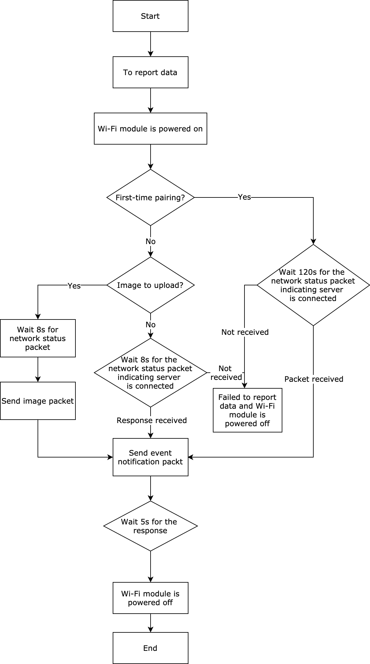
Event notification
The MCU notifies the module of an event through the command 0x60. If an event contains an image, the module will enable the image transmission on receiving this command.
- For more information about the event code, see Appendix 1.
- If an event contains an image, the module will wait for 20 seconds for the MCU to transmit the image. After a 20-second timeout period, the module will exit from receiving images and return a failure code to the MCU through the command
0x62. - Every time the MCU transmits an image, it first sends
0x60to notify the module to enable the image upload function. - A single event only triggers transmitting one image. If it has multiple images to upload, the MCU should repeat the process for each image.
The MCU sends the following command:
| Field | Bytes | Description |
|---|---|---|
| Header | 2 | 0x55aa |
| Version | 1 | 0x00 |
| Command | 1 | 0x60 |
| Data length | 2 | 0x04 |
| Data | 2 | Event code: 0x0000: anti-pry alert 0x0001: remote unlocking request 0x0002: fingerprint attempt 0x0003: password attempt 0x0004: face attempt 0x0005: palm print attempt 0x0006: finger vein attempt 0x0007: fingerprint unlocking |
| - | 1 | Whether the event contains an image: 0x00: no image contained. The subsequent data is invalid. 0x01: image contained. |
| - | 1 | The number of images (≤10): 0x00: The content of this field is invalid. |
| Checksum | 1 | Start from the header, add up all the bytes, and then divide the sum by 256 to get the remainder. |
For example, 55 AA 00 60 00 04 00 00 01 01 18
The module returns the following command:
| Field | Bytes | Description |
|---|---|---|
| Header | 2 | 0x55aa |
| Version | 1 | 0x00 |
| Command | 1 | 0x60 |
| Data length | 2 | 1 |
| Data | 1 | The result: 0: message received. Other values: failed. |
| Checksum | 1 | Start from the header, add up all the bytes, and then divide the sum by 256 to get the remainder. |
For example, 55 AA 00 60 00 01 00 93
Image upload
The image can be transmitted through SPI or UART.
-
A single packet is limited to 15 KB for UART transmission.
-
A single packet is limited to 30 KB for SPI transmission.
-
During image transmission, the module waits for five seconds for the next packet. After a timeout period, the module will exit from receiving images and return a failure code to the MCU through the command
0x62. -
To retransmit the lost packet, the MCU must initiate image transmission through the command
0x60. -
During SPI transmission, the module acts as a slave and the MCU as a master. The module acknowledges receipt of data through the serial port.
Note: If you use the module to associate images with events, the reported time must be consistent with the one in the commands
0x60and0x61.
The MCU sends the following command:
| Field | Bytes | Description |
|---|---|---|
| Header | 2 | 0x55aa |
| Version | 1 | 0x00 |
| Command | 1 | 0x61 |
| Data length | 2 | N |
| Data | 7 | Data[0]: indicates whether the local time flag is valid. 0: The local time flag is invalid and time data is not processed. 1: The local time flag is valid and time data is represented in local time. 2: The local time flag is valid and time data is represented in GMT. Data[1]: indicates the year. For example, 0x00 indicates the year 2000. Data[2]: indicates the month, ranging from 1 to 12. Data[3]: indicates the day, ranging from 1 to 31. Data[4]: indicates the hour, ranging from 0 to 23. Data[5]: indicates the minute, ranging from 0 to 59. Data[6]: indicates the second, ranging from 0 to 59. |
| - | 2 | Image ID: the identifier of one image. |
| - | 2 | The total number of packets: the number of packets used to transmit the total images. |
| - | 2 | The serial number of the packet, starting with 0: indicates the serial number of the current packet. |
| - | N | Image data |
| Checksum | 1 | Start from the header, add up all the bytes, and then divide the sum by 256 to get the remainder. |
The module returns the following command:
| Field | Bytes | Description |
|---|---|---|
| Header | 2 | 0x55aa |
| Version | 1 | 0x00 |
| Command | 1 | 0x61 |
| Data length | 2 | 1 |
| Data | 1 | The result: 0: message received. Other values: failed. |
| Checksum | 1 | Start from the header, add up all the bytes, and then divide the sum by 256 to get the remainder. |
Image upload result
-
Get the image upload result. If the module returns a failure code, the image upload failed and the transmission should be stopped.
-
If the module returns a success code, the MCU should include the image ID and the time returned by the module in event reporting.
The module sends the following command:
| Field | Bytes | Description |
|---|---|---|
| Header | 2 | 0x55aa |
| Version | 1 | 0x00 |
| Command | 1 | 0x62 |
| Data length | 2 | 9 |
| Data | 2 | Image ID: the identifier of one image. |
| - | 6 | The time when the current image is uploaded: Data[1]: indicates the year. For example, 0x00 indicates the year 2000. Data[2]: indicates the month, ranging from 1 to 12. Data[3]: indicates the day, ranging from 1 to 31. Data[4]: indicates the hour, ranging from 0 to 23. Data[5]: indicates the minute, ranging from 0 to 59. Data[6]: indicates the second, ranging from 0 to 59. |
| - | 1 | The result: indicates whether the image upload succeeded. If upload failed, the time data is invalid. 0: Upload succeeded. 1: Upload failed due to network disconnection. 2: Upload failed due to image size limits of 30 KB. 3: Upload failed due to image transmission timeout. 4: Upload failed due to other reasons. |
| Checksum | 1 | Start from the header, add up all the bytes, and then divide the sum by 256 to get the remainder. |
The MCU returns the following command:
| Field | Bytes | Description |
|---|---|---|
| Header | 2 | 0x55aa |
| Version | 1 | 0x00 |
| Command | 1 | 0x62 |
| Data length | 2 | 1 |
| Data | 1 | The result: 0: All images have been uploaded. Other values: There are still images to be uploaded. |
| Checksum | 1 | Start from the header, add up all the bytes, and then divide the sum by 256 to get the remainder. |
Image upload status
Get the image upload status. If the module returns a failure code, the image upload failed and the transmission should be stopped.
-
If
0is returned, there is no image to be uploaded. The event ID and image ID are invalid. -
The time returned by the module only supports the local time.
-
This command is sent through the serial port to get the current processing status of the module. What SPI gets is the status of the previous SPI data transmission.
The MCU sends the following command:
| Field | Bytes | Description |
|---|---|---|
| Header | 2 | 0x55aa |
| Version | 1 | 0x00 |
| Command | 1 | 0x63 |
| Data length | 2 | 0x0000 |
| Data | 1 | |
| Checksum | 1 | Start from the header, add up all the bytes, and then divide the sum by 256 to get the remainder. |
The module returns the following command:
| Field | Bytes | Description | |
|---|---|---|---|
| Header | 2 | 0x55aa | |
| Version | 1 | 0x00 | |
| Command | 1 | 0x63 | |
| Data length | 2 | 11 | |
| Data | Status data of image upload | 1 | Status: 0: Image transmission is not triggered. 1: The module is receiving the image. 2: The image is being uploaded to the cloud. 3: The image is uploaded to the cloud successfully. 4: The module fails to get the URL. 5: Image upload failed. 6: Image transmission times out. 7: The image exceeds size limits. |
| 2 | Event code: 0x0000: anti-pry alert. … |
||
| 2 | Image ID: the identifier of one image. | ||
| Time data, only local time available | 6 | The time when the current image is uploaded: Data[1]: indicates the year. For example, 0x00 indicates the year 2000. Data[2]: indicates the month, ranging from 1 to 12. Data[3]: indicates the day, ranging from 1 to 31. Data[4]: indicates the hour, ranging from 0 to 23. Data[5]: indicates the minute, ranging from 0 to 59. Data[6]: indicates the second, ranging from 0 to 59. |
|
| Checksum | 1 | Start from the header, add up all the bytes, and then divide the sum by 256 to get the remainder. |
Image capturing and video stream
- To simplify processing logic, we integrate image capturing into the Wi-Fi module.
Image upload
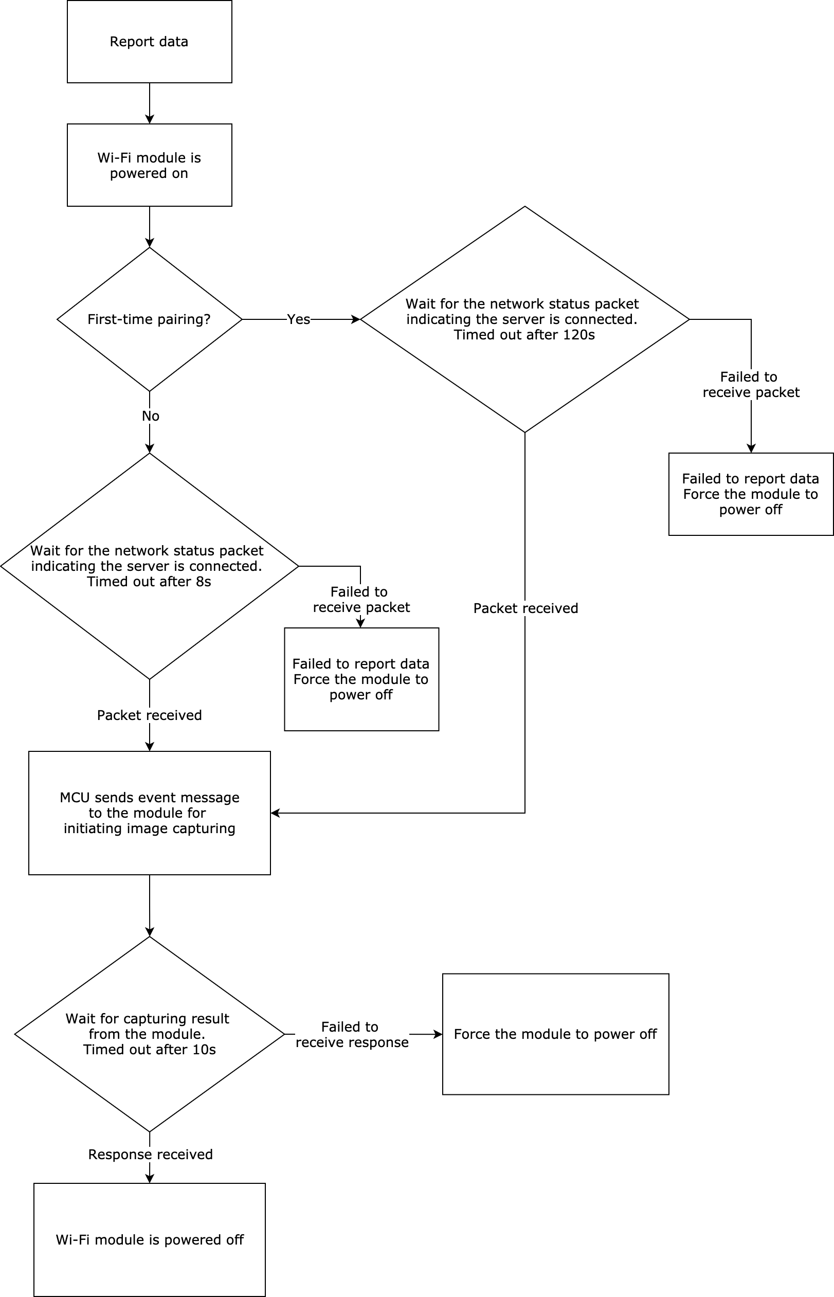
Trigger capturing
The MCU notifies the module of an event through the command 0x64. If this event triggers capturing, the module will enable relevant functionality on receiving this command.
-
For more information about the event code, see appendix 1.
-
When an event triggers image capturing, the module will capture images and upload them to the server. If the server does not return a success code within the timeout period, the module will return a failure code to the MCU through the command
0x62. -
Every time an event triggers capturing, this command must be sent to notify the module to enable the capturing feature.
-
You can specify capturing modes by sub-commands.
-
To associate an event with the captured images or video stream, the module must report the corresponding recorded DP event.
The MCU sends the following command:
| Field | Bytes | Description |
|---|---|---|
| Header | 2 | 0x55aa |
| Version | 1 | 0x00 |
| Command | 1 | 0x64 |
| Data length | 2 | 0x01+0x05+0x07 |
| Data | 1 | Sub-command: 0x00 by default |
| 2 | Event code: 0x0000: anti-pry alert 0x0001: remote unlocking request 0x0002: fingerprint attempt 0x0003: password attempt 0x0004: face attempt 0x0005: palm print attempt 0x0006: finger vein attempt 0x0007: fingerprint unlocking |
|
| 1 | Whether to capture an image. 0x00: no capturing. The subsequent data is invalid. 0x01: capturing. |
|
| 1 | Capturing modes: 0x00: single capturing. 0x01: continuous capturing. 0x02: smart capturing. |
|
| 1 | The number of images captured (≤16): 0x00: The content of this field is invalid. |
|
| 7 | The data length is 7 bytes. Data[0]: indicates whether the local time flag is valid. 0: The local time flag is invalid and time data is not processed. Time is required by default. 1: The local time flag is valid and time data is represented in local time. 2: The local time flag is valid and time data is represented in GMT. Data[1]: indicates the year. For example, 0x00 indicates the year 2000. Data[2]: indicates the month, ranging from 1 to 12. Data[3]: indicates the day, ranging from 1 to 31. Data[4]: indicates the hour, ranging from 0 to 23. Data[5]: indicates the minute, ranging from 0 to 59. Data[6]: indicates the second, ranging from 0 to 59. |
|
| Checksum | 1 | Start from the header, add up all the bytes, and then divide the sum by 256 to get the remainder. |
The module returns the following command:
| Field | Bytes | Description |
|---|---|---|
| Header | 2 | 0x55aa |
| Version | 1 | 0x00 |
| Command | 1 | 0x64 |
| Data length | 2 | 1 |
| Data | 1 | The result: 0: message received. Other values: failed. |
| Checksum | 1 | Start from the header, add up all the bytes, and then divide the sum by 256 to get the remainder. |
For example, 55 AA 00 64 00 01 00 64
Capturing result
Returns the result of image capturing or video stream.
- When image capturing is triggered, the returned
0indicates successful upload.
The MCU must include the image ID and the time returned by the module in event reporting. - When a video stream is triggered, the returned
0indicates successful streaming.
When the streaming ends, the time in the returned data is invalid. The MCU must determine the trigger type, and power off the module after a timeout.
The module sends the following command:
| Field | Bytes | Description |
|---|---|---|
| Header | 2 | 0x55aa |
| Version | 1 | 0x00 |
| Command | 1 | 0x62 |
| Data length | 2 | 9 |
| Data | 2 | Image ID: the identifier of one image. |
| 6 | The time when the current image is uploaded. Data[1]: indicates the year. For example, 0x00 indicates the year 2000. Data[2]: indicates the month, ranging from 1 to 12. Data[3]: indicates the day, ranging from 1 to 31. Data[4]: indicates the hour, ranging from 0 to 23. Data[5]: indicates the minute, ranging from 0 to 59. Data[6]: indicates the second, ranging from 0 to 59. |
|
| 1 | The result: If the operation failed, time data is invalid. 0: Image upload succeeds or video streaming starts. 1: Connection error. 2: Exceed the maximum size limit. 3: Capturing timeout. 4: Other failure reasons. 5: Streaming ends. |
|
| Checksum | 1 | Start from the header, add up all the bytes, and then divide the sum by 256 to get the remainder. |
The MCU returns the following command:
| Field | Bytes | Description |
|---|---|---|
| Header | 2 | 0x55aa |
| Version | 1 | 0x00 |
| Command | 1 | 0x62 |
| Data length | 2 | 1 |
| Data | 1 | The result: 0: All images have been uploaded. Other values: There are still images to be uploaded. |
| Checksum | 1 | Start from the header, add up all the bytes, and then divide the sum by 256 to get the remainder. |
Configure graphics parameters
- You can use this command to change graphics parameters including image resolution, image quality, and video frame rate, as well as to enable infrared night vision. Your configuration will be remembered by the module, which will be used for later initialization.
- After this command is sent, the module will reboot automatically.
- If your configuration is not sent, the module will be initialized with the default graphics parameters.
- This command must be sent after the module responds with the PID and is initialized (that is, after the module sends the command
0x02).
The MCU sends the following command:
| Field | Bytes | Description |
|---|---|---|
| Header | 2 | 0x55aa |
| Version | 1 | 0x00 |
| Command | 1 | 0x65 |
| Data length | 2 | 0x0004 |
| Data | 1 | Image resolution: 0x00: 320 × 240 pixels 0x01: 640 × 480 pixels |
| 1 | Image compression ratio: 25 50 |
|
| 1 | Video frame rate: 12 15 20 |
|
| 1 | Infrared night vision: 0x00: disable 0x01: enable |
|
| Checksum | 1 | Start from the header, add up all the bytes, and then divide the sum by 256 to get the remainder. |
The module returns the following command:
| Field | Bytes | Description |
|---|---|---|
| Header | 2 | 0x55aa |
| Version | 1 | 0x00 |
| Command | 1 | 0x65 |
| Data length | 2 | 1 |
| Data | 1 | Configuration result: 0x00: success 0x01: failure |
| Checksum | 1 | Start from the header, add up all the bytes, and then divide the sum by 256 to get the remainder. |
Configure graphics register
- You can get the required image effect by configuring graphics registers.
- After this command is sent, the module will reboot automatically.
- If your configuration is not sent, the module will be initialized with the default graphics register.
- This command must be sent after the module responds with the PID and is initialized.
The MCU sends the following command:
| Field | Bytes | Description |
|---|---|---|
| Header | 2 | 0x55aa |
| Version | 1 | 0x00 |
| Command | 1 | 0x66 |
| Data length | 2 | 2N+1 |
| Data | 1 | The number of registers (N) |
| 2N | Data[0]: the address of the register Data[1]: the value of the register |
|
| Checksum | 1 | Start from the header, add up all the bytes, and then divide the sum by 256 to get the remainder. |
The module returns the following command:
| Field | Bytes | Description |
|---|---|---|
| Header | 2 | 0x55aa |
| Version | 1 | 0x00 |
| Command | 1 | 0x66 |
| Data length | 2 | 1 |
| Data | 1 | Configuration result: 0x00: success 0x01: failure |
| Checksum | 1 | Start from the header, add up all the bytes, and then divide the sum by 256 to get the remainder. |
Image download (Not supported currently)
Notify module of image download
- Notify the module to download images and send them to the MCU.
The MCU sends the following command:
| Field | Bytes | Description |
|---|---|---|
| Header | 2 | 0x55aa |
| Version | 1 | 0x00 |
| Command | 1 | 0x65 |
| Data length | 2 | 1 |
| Data | 1 | The image size of a single packet: 0x01: 1024 0x02: 2048 0x03: 3072 0x04: 4096 |
| Checksum | 1 | Start from the header, add up all the bytes, and then divide the sum by 256 to get the remainder. |
The module returns the following command:
| Field | Bytes | Description |
|---|---|---|
| Header | 2 | 0x55aa |
| Version | 1 | 0x00 |
| Command | 1 | 0x65 |
| Data length | 2 | 1 |
| Data | 1 | The result: 0: message received and image download starts. Other values: failure. |
| Checksum | 1 | Start from the header, add up all the bytes, and then divide the sum by 256 to get the remainder. |
Image transmission
The serial port sends the following command:
| Field | Bytes | Description |
|---|---|---|
| Header | 2 | 0x55aa |
| Version | 1 | 0x00 |
| Command | 1 | 0x66 |
| Data length | 2 | N |
| Data | 2 | Image ID: the identifier of one image. |
| 2 | The total number of packets: the number of packets used to transmit the total images. | |
| 2 | The serial number of the packet, starting with 0: indicates the serial number of the current packet. | |
| N | Image data | |
| Checksum | 1 | Start from the header, add up all the bytes, and then divide the sum by 256 to get the remainder. |
The MCU returns the following command:
| Field | Bytes | Description |
|---|---|---|
| Header | 2 | 0x55aa |
| Version | 1 | 0x00 |
| Command | 1 | 0x66 |
| Data length | 2 | 1 |
| Data | 1 | The result: 0: message received. Other values: failure. |
| Checksum | 1 | Start from the header, add up all the bytes, and then divide the sum by 256 to get the remainder. |
Appendix 1: Event code of image upload
| Event status | Description | Status value |
|---|---|---|
| Status 1 | Anti-pry alert | 0x0000 |
| Status 2 | Remote unlocking request | 0x0001 |
| Status 3 | Fingerprint attempt | 0x0002 |
| Status 4 | Password attempt | 0x0003 |
| Status 5 | Card attempt | 0x0004 |
| Status 6 | Face attempt | 0x0005 |
| Status 7 | Palm print attempt | 0x0006 |
| Status 8 | Finger vein attempt | 0x0007 |
| Status 9 | Unlock with fingerprint | 0x0008 |
| Status 10 | Unlock with password | 0x0009 |
| Status 11 | Unlock with card | 0x000A |
| Status 12 | Unlock with face recognition | 0x000B |
| Status 13 | Unlock with palm vein | 0x000C |
| Status 14 | Unlock with finger vein | 0x000D |
| Status 15 | Unlock with temporary password | 0x000E |
| Status 16 | Unlock with dynamic password | 0x000F |
| Status 17 | Remote unlocking | 0x0010 |
| Status 18 | Report offline password unlocking | 0x0011 |
| Status 19 | Report doorbell request | 0x0012 |
| Status 20 | Duress alarm | 0x0013 |
| Status 21 | Low battery warning | 0x0014 |
| Status 22 | Mechanical key attempt | 0x0015 |
| Status 23 | High temperature alert | 0x0016 |
| Status 24 | Doorbell ringing and remote unlocking | 0x0017 |
| Status 25 | Loitering alert | 0x0018 |
| Status 26 | Lock tampering | 0x0019 |
| Status 27 | Unlock with special fingerprint | 0x001A |
| Status 28 | Unlocking in arm mode | 0x001B |
Appendix 2: SPI configuration
Default parameters are as follows.
| Parameter name | Description | Status value |
|---|---|---|
| Clock | Clock rate | 6000000 |
| Clock mode | - | SPI_SCLK_Mode0 |
| Level of first byte | - | SPI_TCTRL_FBS_MSB |
| Cs | Chip select signal | Low level |
| Byte alignment | - | 8-bit |
Protocol version
The following table lists the change history for this document.
| Version | Description | Date | Remark |
|---|---|---|---|
| 1.0.0 | The first release. | September 15, 2018 | Add |
| 1.0.1 | Added interface for requesting multiple temporary passwords. | October 19, 2018 | Modify |
| 1.0.2 | 1. Added the response parameter when a request for multiple temporary passwords returns no password. 2. Added description of combined unlocking methods. |
December 17, 2018 | Modify |
| 1.0.3 | Added the command to get DP cache. | July 10, 2019 | Modify |
| 1.0.4 | Added low power mode to the network status. | July 13, 2019 | Modify |
| 1.0.5 | 1. Added offline dynamic password. 2. Added the report of the MCU serial number. | September 9, 2019 | Modify |
| 1.0.6 | Added periodic temporary password (with schedule list). | October 10, 2019 | Modify |
| 1.0.7 | 1. Added rapid status reporting. 2. Added pairing mode of EZ and AP coexistence. 3. Added the field of pairing method in product information query. 4. Added functionality of locks with camera. 5. Added the field of capability (cap) to the product information. 6. Added status notification of module reset. 7. Added acquisition of image upload status. |
July 9, 2020 | Modify |
| 1.0.8 | Added data reporting through mobile network operators. | July 13, 2020 | Modify |
| 1.0.9 | Extended image upload command that applies to module integrated with image capturing. | July 21, 2020 | Modify |
| 1.0.10 | Added protocol to proactively get Wi-Fi status and Unix timestamp. | July 30, 2020 | Modify |
| 1.0.11 | 1. Modified logic of uploading images. The MCU triggers image transmission when receiving the network status packet rather than the 0x04 status packet. 2. Modified the correlation logic between the image and the time. Use the module to associate images with events, so the time when an event is reported must be consistent with the one when the MCU transmits an image. |
September 12, 2020 | Modify |
| 1.0.12 | Added debugging command 0xDB to define error severities. |
October 14, 2020 | Modify |
| 1.0.13 | 1. Added positional notation settings. 2. Added protocols for dynamic passwords and multiple temporary passwords. |
January 6, 2021 | Modify |
| 1.0.14 | Added command for short videos and video stream in 0x64 and modified the field of capturing modes. |
January 25, 2021 | Modify |
| 1.0.15 | Added command 0xF0 for SPI production test. |
February 24, 2021 | Modify |
| 1.0.16 | 1. Added two commands 0x65 and 0x66 for configuring graphics parameters. 2. Removed protocols related to rapid reporting. |
February 26, 2021 | Modify |
| 1.0.17 | 1. Modified the trigger types in command 0x64 and removed the type of short video. 2. Added the returned status of streaming end in command 0x62. |
March 27, 2021 | Modify |
| 1.0.18 | Added four items in Appendix 1. | April 8, 2021 | Modify |
Is this page helpful?
YesFeedbackIs this page helpful?
YesFeedback


