Create Electrical Products
This topic describes how to create electrical products with a no-code solution on the Tuya Developer Platform, using Wi-Fi + Bluetooth energy monitoring socket as an example.
Create electrical products
Procedure
-
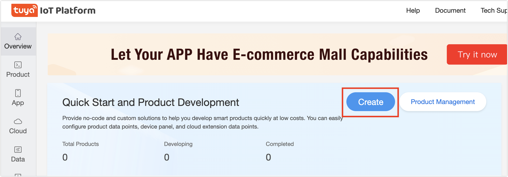
Log in to Developer Platform.
-
Click Create.
-
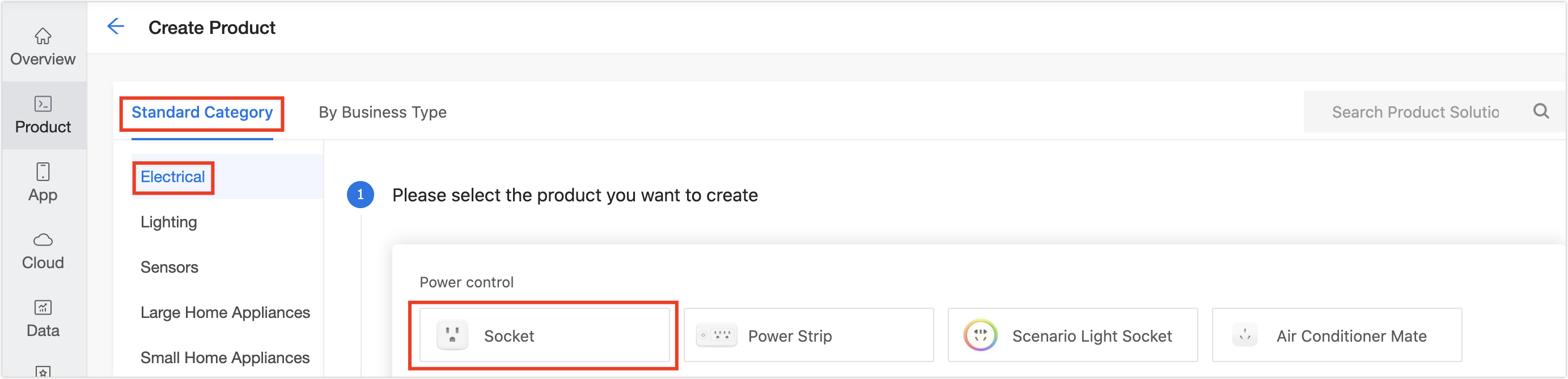
Find Standard Category, and click Electrical > Socket.
-
In the Choose a product plan section, click Zero-Coding Development > Wi-Fi+Bluetooth> Energy Monitor > Power Statistics Socket_Wi-Fi_Bluetooth Low Energy (LE).
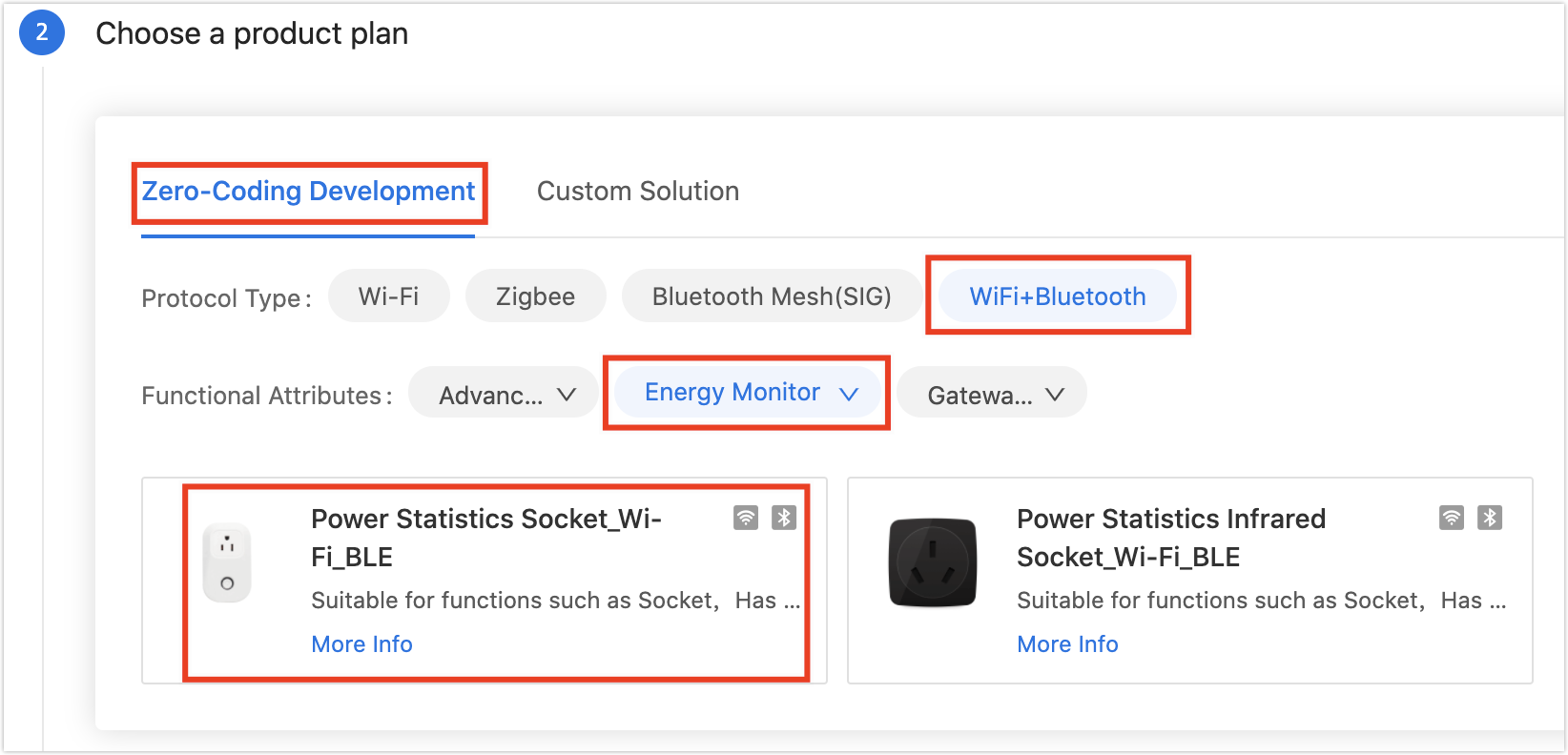
Note: If the functions provided by the no-code solution fails to meet your requirements, you can turn to custom solutions with the reference of SoC Custom Firmware.
-
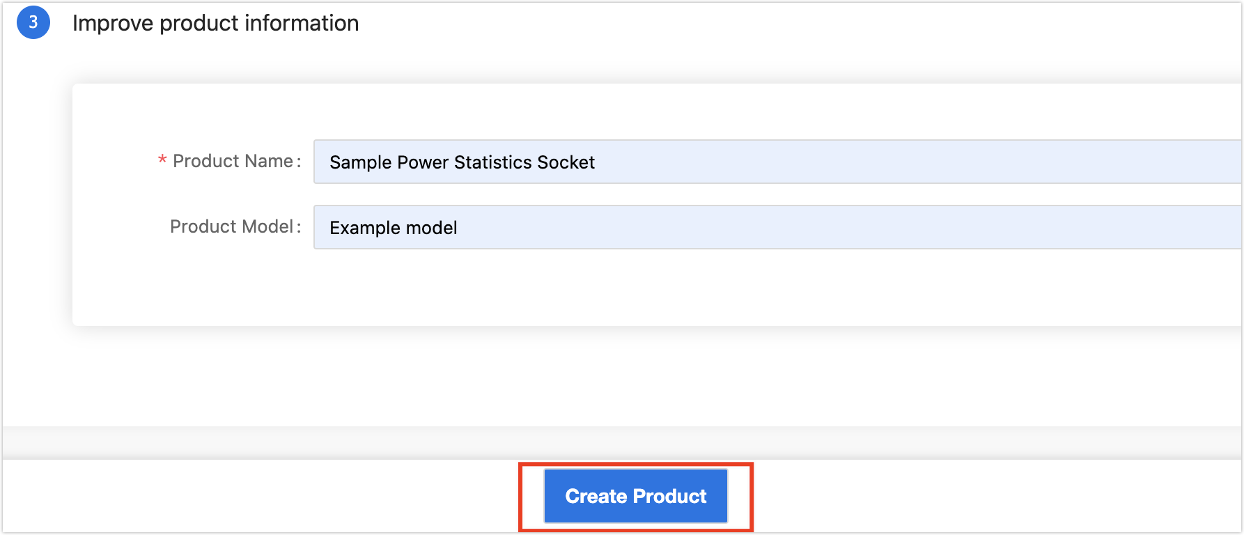
Complete product information.
- Product Name (required): Enter the brand and product name. The name will be displayed on the app control panel.
- Product Model (optional): Enter the product’s model. Multiple models are available, separated by a comma.
Note:
- The model will not be displayed on the app. It is recommended to enter the internal model name or customer’s product model to ease product and order management on the Developer Platform.
- The product information above can be modified in subsequent steps. See Modify product information
-
Click Create. When a product is created, you will see Create Standard Functions of the step of Function Definition.
Define product features
Procedure
- In the dialog box of Create Standard Functions, click Confirm.
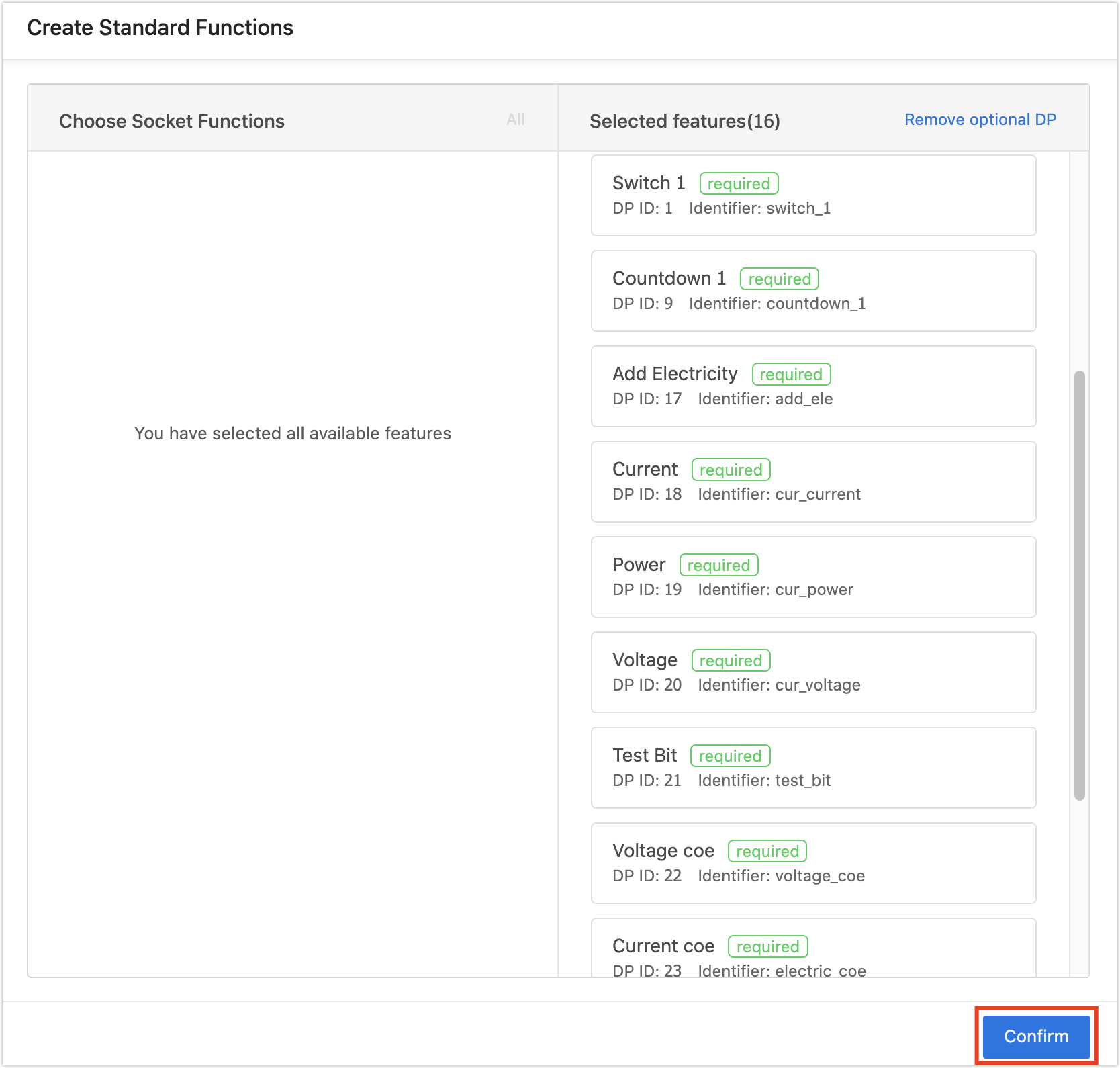
Note:
- The required functions cannot be removed from the selected functions.
- Select data points for different products according to actual interface prompts.
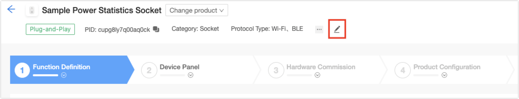
2.(Optional)Modify product information.
The product information can be modified in any stage.
3. (Optional) On Function Definition page, enable Cloud Functions as needed.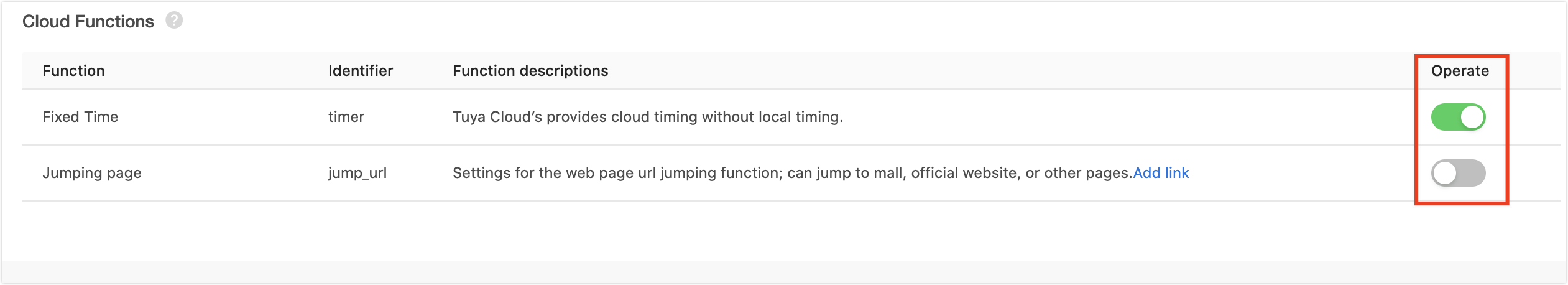
4. Click Next: Device Panel at the bottom of the page. You will see Device Panel page.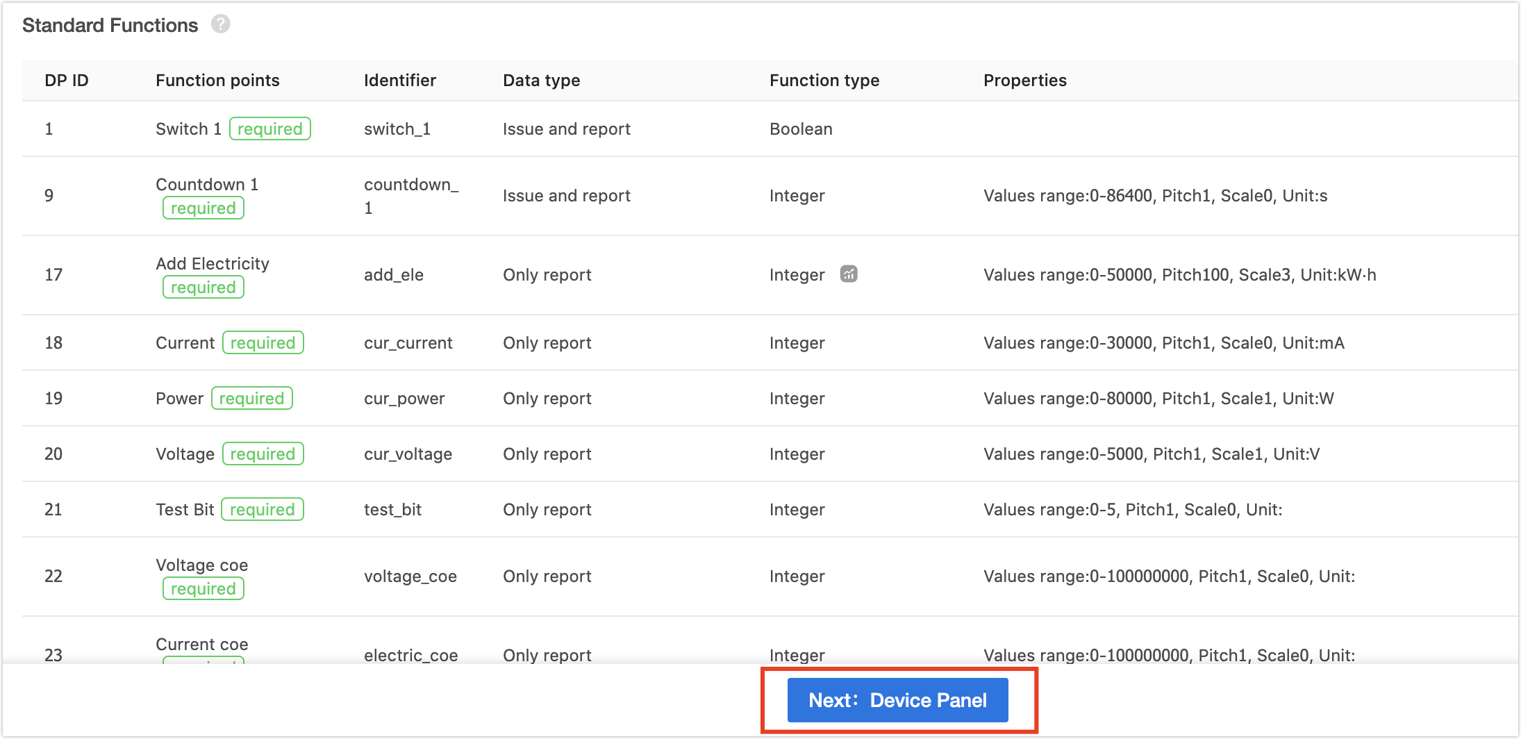
Configure device panel
This section describes how to configure a device panel, using a public panel as an example. If you require custom panels or panel editing, you can proceed with relevant operations as per the prompts.
Procedure
-
On the Device Panel page, find an ideal panel and click Apply.
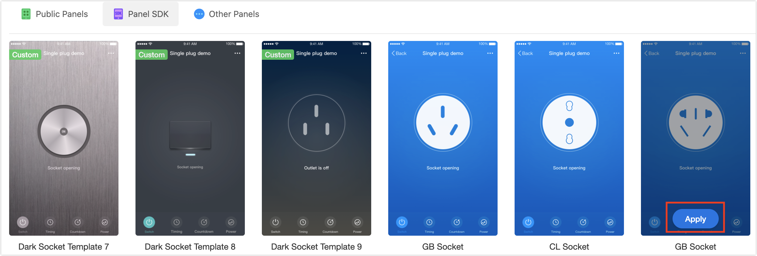
Note: More panels are available after upgrading to an enterprise account.
-
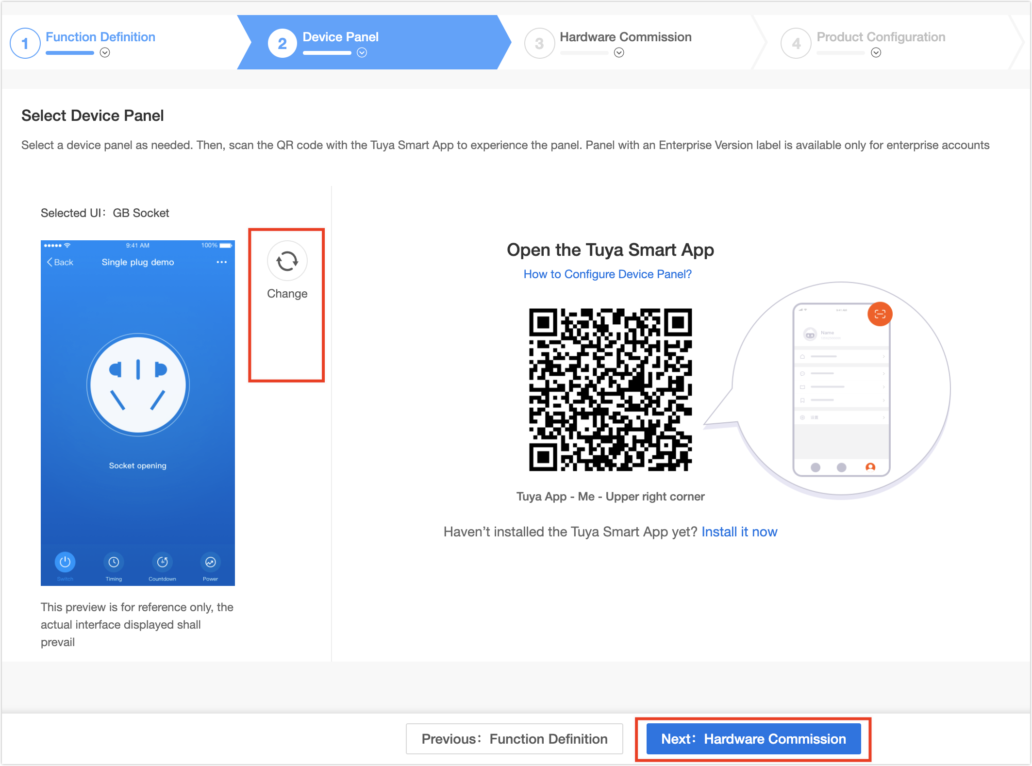
You can change or edit the panel as needed. Scan QR code with Tuya app to preview.
-
Click Next: Hardware Commission. You will see Hardware Commission page.
Hardware commission
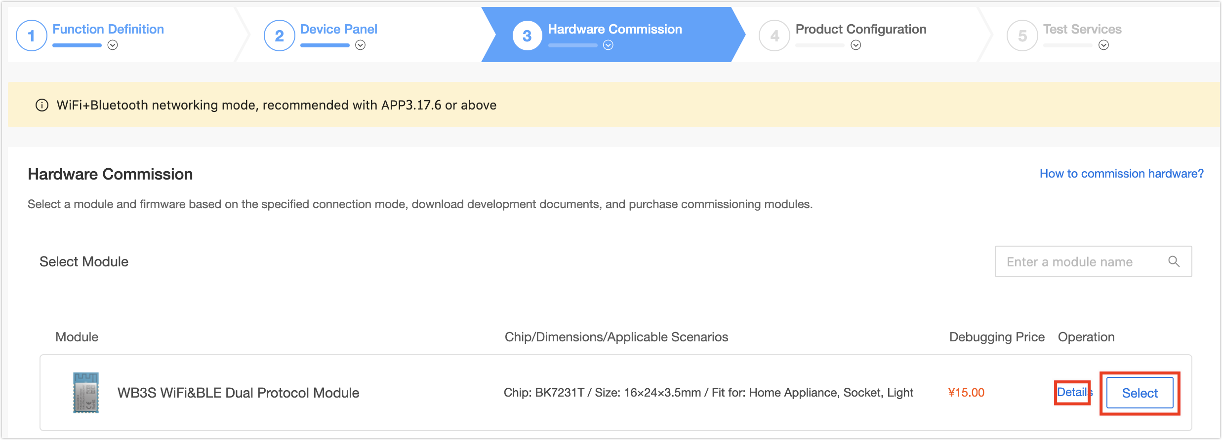
This section uses the WB3S Wi-Fi module to describe hardware commission. It is recommended that professional engineers perform hardware commissioning.
Hardware configuration information
I/O port configuration
Your configured I/O ports and drive level determine how the firmware works. For example, configure the I/O 3 port as button and Low-level active. When the firmware detects that the I/O 3 button input signal changes from high to low, the button function will be triggered. If the I/O 3 port is incorrectly connected to the LED light or relay, the firmware cannot detect the button input signal.
Function configuration
You can implement different firmware functionality through custom configuration. For example, if you set Long press network pairing time as 3 seconds, pressing the button for more than 3 seconds will trigger pairing mode switching.
Notice:
- After the configuration is saved and the module is sent, the I/O and configured functions of the module cannot be modified. If the hardware schematic diagram is inconsistent with the selected I/O port, you can modify and save the configuration and send the module again.
- Currently, the energy monitoring socket only supports pulse-count chips including bl0937 and hlw8012. If other types of chips are used, the power statistics function will be unavailable.
Procedure
-
Select a module as needed after checking the module details.
-
Configure firmware parameters in the Generate firmware 1 To be generated area. The specific parameter configuration is as follows.
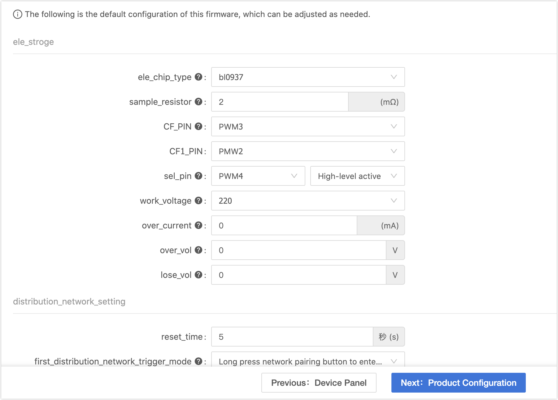
Parameter type Parameters Description ele_stroge ele_chip_type Select a chip as needed.
Currently, only pulse-count chips are compatible, including bl0937 and hlw8012.sample_resistor (mΩ) Value range: 1mΩ and 2mΩ. CF_PIN This I/O port is used to collect the pulse output from the CF pin of the sampling chip, and calculate the power value. CF1_PIN This I/O port corresponds to the CF1 pin of the power statistics chip and is used to detect the voltage and current value. sel_pin This I/O port is connected to the SEl pin of the sampling chip and is used to determine whether the pulse of the sampling CF1 pin is voltage or current. The voltage pulse is detected at high level, and the current pulse is detected at low level. work_voltage It indicates the socket operating voltage, also known as calibration voltage. You can choose 120V or 220V. over_current The overcurrent threshold. The occurrence of overcurrent triggers the relay to power off
Value range: 0 to 30000 mA.Note:
- Enter the current value if overcurrent protection is required. It is recommended to set the current value to 10% greater than the relay specification.
- Enter 0 if overcurrent protection is not required.
over_vol Overvoltage threshold. The occurrence of overvoltage triggers the relay to power off. - If the **work_voltage** is 220V, select the range of 220V to 300V accordingly.
- If the **work_voltage** is 120V, select the range of 120V to 200V accordingly.
lose_vol Under voltage threshold. The occurrence of overvoltage triggers the relay to disconnect. - If the **work_voltage** is 220V, select the range of 73V to 176V accordingly.
- If the **work_voltage** is 120V, select the range of 40V to 96V accordingly.
distribution_network_setting reset_time The time of pressing and holding the button to restore the device.
Value range: 3 to 10 seconds.first_distribution_network_trigger_mode Pairing triggering mode when the socket is powered on for the first time. - Start continuous fast flash when initially power on, no re-link logic included: The indicator keeps blinking upon the first time pairing after power-on. The function of unexpected-trigger-proof is not included.
- Long press network pairing button to enter fast flash pairing status for 3 minutes, re-link logic included: Press the pairing button until the indicator starts blinking, which indicates that the pairing is ready to start. The function of unexpected-trigger-proof is included.
- Start fast flash when initially power on for 3 minutes, re-link logic included: The indicator keeps blinking upon the first time pairing after power-on, which indicates that the pairing is ready to start. The function of unexpected-trigger-proof is included.
Note: With the 3-minute timeout unexpected-trigger-proof function, when a device is locally reset, if it is not paired by another account in 3 minutes, it will retain all the configuration information of the previous account; whereas if it is paired by another account in 3 minutes, then it will be paired as a new device. If you want to remove pairing information of this device from the previous account, you use the app, including Tuya Smart, Smart Life, and OEM app, to remove the configuration or restore factory defaults.
netled1 Select a pin from the pull-down menu and the selected one cannot be used for other parameter configuration. unlink_network_led_status Set the Wi-Fi indicator status when the socket is not connected to the network. Note:
- It is advisable to set to relay status when applying the single light solution.
- It is advisable to set to off when applying the double light solution.
link_network_led_status Set the Wi-Fi indicator status as needed when the socket is connected to the network. Note:
- It is advisable to set to relay status when applying the single light solution.
- It is advisable to set to on when applying the double light solution.
channel_num1 button_type Select level_trig or edge_trig. button1 Select a pin from the pull-down menu and the selected one cannot be used for other parameter configuration. relay1_type Select Electric holding relay or Magnetic holding relay. rl1 Select a pin from the pull-down menu and the selected one cannot be used for other parameter configuration. relay led1 Select a pin from the pull-down menu and the selected one cannot be used for other parameter configuration. Note: It is recommended to select None for the single light solution, and select as needed for the double light solution.
channel1_status Select it as needed. - Power off: Each time the device is powered on again, the relay is off.
- Power on: Each time the device is powered on again, the relay is on.
- Power off memory: Each time the device is powered on again, the relay is in the last status before power off.
-
When the configuring is finished, click Online Firmware Generation.
-
Development debugging. Follow the interface prompts, view the circuit schematic, download the Tuya Cloud Test app, and perform debugging.
-
After debugging is completed, Click Next: Product Configuration. You will see Product Configuration page.
Product configuration
Configure items according to operating instructions. When the configuring is finished, click Next: Test Services. 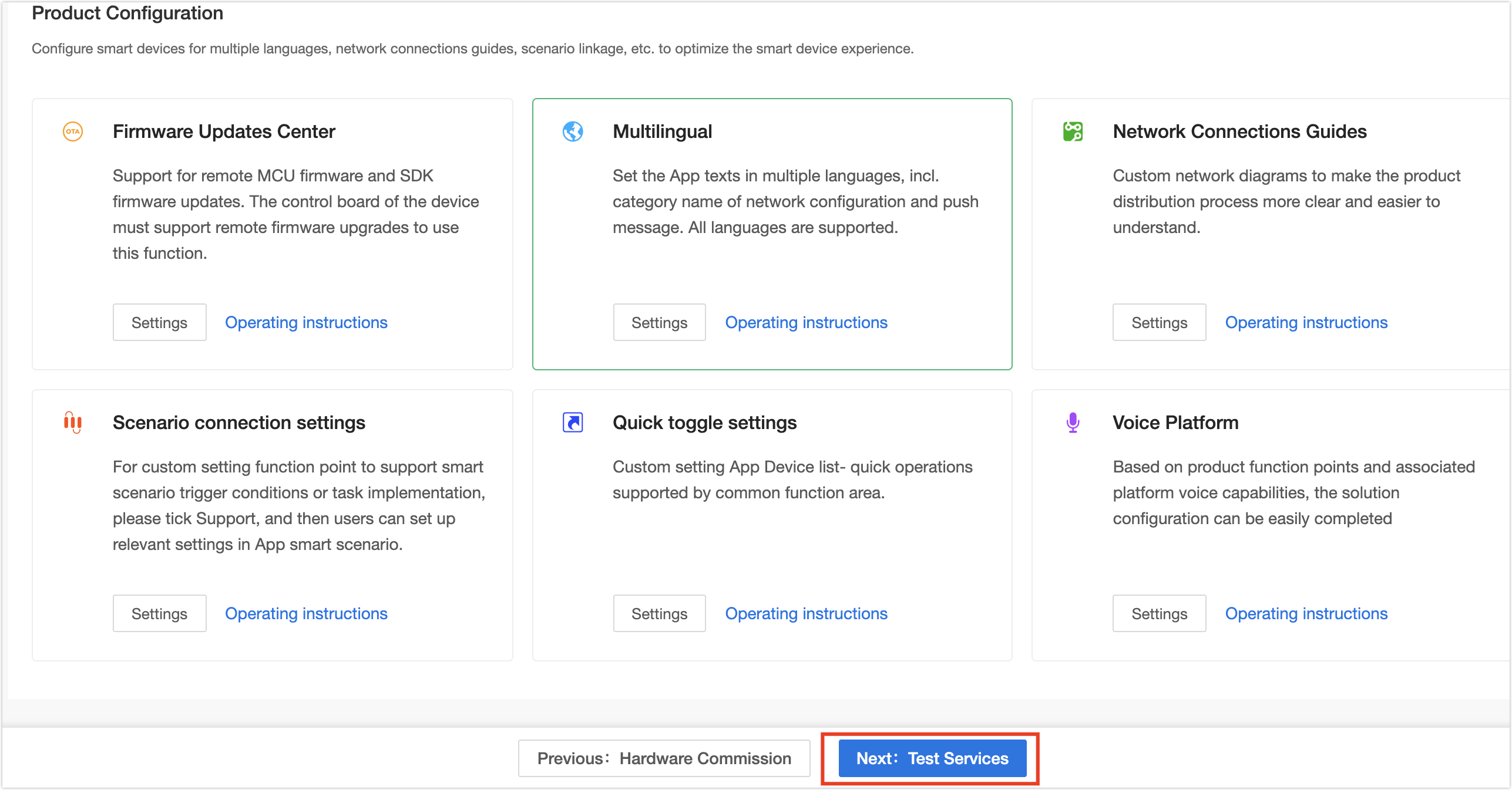
Test services
Follow the prompts on the page to perform a self-service test with the Tuya Cloud Test app and produce a test report. You can also subscribe to the Tuya Test service. When the test is completed, click Next: Product Release. 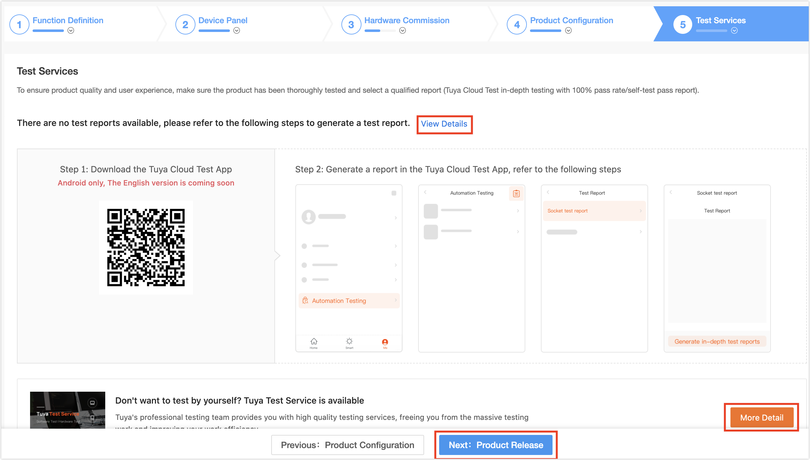
Note:
- Tuya Cloud Test app is only available for Android.
- For more information about the Tuya Cloud Test process, see Tuya Cloud Test App.
- Do not delete developing or developed products to avoid data loss and affecting proper product usage.
Is this page helpful?
YesFeedbackIs this page helpful?
YesFeedback


