GR4 Module Datasheet
GR4 is an embedded low-power quad-band GSM/GPRS module that Tuya has developed. It supports the SM/GPRS radio communication protocol (3GPP Rel.13 and 3GPP Rel.14). GR4 contains a highly integrated SoC RDA8955L (which is internally embedded with an application processor, a low-power multi-band GSM transceiver, a power management unit (PMU) and audio components) and a few peripherals.
After a period of service, this module will become deprecated due to product upgrades and iterations, user requirements, production inventory, or other reasons. To improve the compatibility of your smart devices and minimize the impact on your use, Tuya continues to provide webpage documentation of deprecated modules, but no longer maintains or updates the documentation. The content herein is for reference only.
If you have any questions, submit a ticket to contact Tuya or consult Tuya’s account manager to request support.
Overview
GR4 further contains an embedded low-power 32-bit central processing unit (CPU), is integrated with 32-Mb 1.8-V double data rate pseudo static random access memory (DDR PSRAM), 32-Mb 1.8-V SPI NOR Flash, and supports interfaces including UART, I2C, SPI, PWM, ADC, AUDIO, SIM, etc.
Features
- Embedded low-power 32-bit RDA RISC Core processor
- Working voltage: 3.8 ± 0.4V
- Peripherals: 16 GPIOs, 2 universal asynchronous receiver/transmitters (UART), 2 pulse width modulations (PWM), 1 analog-to-digital converter (ADC), 2 serial peripheral interfaces (SPI) and 1 inter-integrated circuit (I2C)
- SIM: 3V/1.8V SIM card
- USB interface: USB 1.1
- GSM/GPRS network:
- GSM Phase 2/2+
- GSM850/GSM900 33 dBm±2 db; DCS1800/PCS1900 30 dBm±2 db
- Receiving sensitivity -107.5 dBm
- 50Ω characteristic impedance. The module can have an external SMA rod antenna or IPEX can connect to an FPC antenna.
- Data rate: 85.6 kbps (downlink), 85.6 kbps (uplink)
- Network protocol features: TCP/UDP/FTP/PPP
- Working temperature: -20 to 85℃
Applications
- Public utilities: meter reading (water, gas, and electricity), intelligent water affairs (pipe network, leakage and quality inspection), smart fire extinguisher, fire hydrant, etc.
- Smart health: drug traceability, remote medical monitoring, blood pressure meter, blood glucose meter, heart armor monitoring, baby monitor, etc.
- Smart city: smart street lights, smart parking, urban trash can management, public safety alarms, urban environment monitoring (water pollution, noise, air quality PM2.5, etc.)
- Consumers: wearable devices, bicycles, mopeds anti-theft, smart luggage, VIP tracking (children, elderly, pets, and vehicle rental), and payment/POS machines
- Agricultural environment: precision planting (environment parameters: water, temperature, sunshine, biocide, and fertilizer), animal husbandry (health and tracking), aquaculture and food safety traceability
- Logistics warehousing: asset, container tracking, warehouse management, fleet management tracking, and logistics status tracking
- Smart building: access control, smart HVAC, smoke detection, fire detection, and elevator failure/repair
- Manufacturing industry: production, equipment status monitoring, energy facilities, oil and gas monitoring, chemical park monitoring, large-scale rental equipment, and predictive maintenance (home appliances, machinery, etc.)
Module interfaces
Pin distribution
The GR4 module has 41 pins. Among them, there are 38 LCC pins, and 3 GND pins at the bottom. This part illustrates module interfaces and their definitions in detail.

Pin definition
| Pin number | Symbol | I/O type | Function |
|---|---|---|---|
| 1 | PWRKEY | I | PowerKey pin, which internally pulled up to realize power-on self-start |
| 2 | SPI1_CS/GPIO_10 | I/O | SPI |
| 3 | SPI1_CLK/GPIO_8 | I/O | SPI |
| 4 | SPI1_DO/GPIO_11 | I/O | SPI |
| 5 | SPI1_DI/GPIO_12 | I/O | SPI |
| 6 | UART1_CTS/GPIO_2 | I/O | Be allowed to send data |
| 7 | UART1_RTS/GPIO_3 | I/O | DTE requests to send data to the module |
| 8 | UART1_TXD/GPIO_1 | I/O | The module transmits data |
| 9 | UART1_RXD/GPIO_0 | I/O | The module receives data |
| 10 | UART1_DCD/GPIO_31 | I/O | Carrier detection (when the pin is effective, it means the communication link has been established) |
| 11 | UART1_RI/GPIO_30 | I/O | The module outputs the ring prompt |
| 12 | UART1_DTR/GPIO_29 | I/O | DTE is prepared |
| 13 | 32K_OUT/GPIO_33 | I/O | The network status indicator |
| 14 | ADC0 | I | Analog-to-digital converter |
| 16,17 | SPKP, SPKN | O | Differential audio output, which can directly drive an 8 Ω loudspeaker |
| 18,19 | MICP,MICN | I | Differential audio input |
| 20 | SIM_RST | I | A SIM card resets |
| 21 | SIM_VDD | O | The power supply voltage of a SIM card |
| 22 | SIM_DAT | I/O | Data cables for a SIM card |
| 23 | SIM_CLK | O | Clock lines for a SIM card |
| 24 | VDDIO | O | Output the voltage of 2.8V 10mA |
| 25 | HOST_RXD | I | Used for software debugging and firmware download |
| 26 | HOST_TXD | I/O | Used for software debugging and firmware download |
| 27 | UART2_RXD/GPIO_4 | I | Hardware UART2 |
| 28 | UART2_TXD/GPIO_5 | O | Hardware UART2 |
| 29 | UART2_RTS/GPIO_7 | I/O | An I2C interface, which needs an external pull-up resistor when used |
| 30 | UART2_CTS/GPIO_6 | I/O | An I2C interface, which needs an external pull-up resistor when used |
| 32 | ANT | I/O | A GPRS RF signal is input and output |
| 34 | RESET | I | Reset module |
| 37, 38 | VBAT | P | Main power supplies of the module, VBAT=3.4 to 4.2V |
| 15, 31, 33, 35, 36, 39, 40 | GND | P | Grounds for the module |
Note:
Pindicates power supply pins and I/O indicates input/output pins.
Electrical parameters
Absolute electrical parameters
| Parameter | Description | Minimum value | Maximum value | Unit |
|---|---|---|---|---|
| Ts | Storage temperature | -40 | 90 | ℃ |
| VBAT | Power supply voltage | -0.3 | 4.2 | V |
| Contact discharge | VBAT, GND | -5 | +5 | KV |
| Contact discharge | Antenna interface | -5 | +5 | KV |
| Contact discharge | Other interfaces | -0.5 | +0.5 | KV |
| Air discharge | VBAT, GND | -10 | +10 | KV |
| Air discharge | Antenna interface | -10 | +10 | KV |
| Air discharge | Other interfaces | -1 | +1 | KV |
Normal working conditions
| Parameter | Description | Minimum value | Typical value | Maximum value | Unit |
|---|---|---|---|---|---|
| Ta | Working temperature | -20 | 25 | 85 | ℃ |
| VBAT | Power supply voltage | 3.4 | 4.0 | 4.2 | V |
| VIL | IO low-level intput | -0.3 | - | VCC*0.25 | V |
| VIH | IO high-level input | VCC*0.75 | - | VCC | V |
| VOL | IO low-level output | - | - | VCC*0.1 | V |
| VOH | IO high-level output | VCC*0.8 | - | VCC | V |
| Imax | IO drive current | - | - | 12 | mA |
TX and RX power consumption
Data transmission mode, GPRS (2 for receiving and 2 for transmitting) CLASS8 & CLASS 12:
| Work status | Current consumption |
|---|---|
| GSM850 | @power level 5, <550mA, typical value 281.6 mA; @power level 10, typical value 148.4 mA; @power level 19, typical value 82.5 mA |
| EGSM900 | @power level 5, <550mA, typical value 315.9mA; @power level 10, typical value 158.2mA; @power level 19, typical value 83.5mA |
| DCS1800 | @power level 0, <450mA, typical value 208.7mA; @power level 5, typical value 125mA; @power level 15, typical value 78.4mA |
| PCS1900 | @power level 0, <450mA, typical value 195.6mA; @power level 5, typical value 118.5mA; @power level 15, typical value 78.4mA |
Data transmission mode, GPRS (4 for receiving and 1 for transmitting) CLASS8 & CLASS 12:
| Work status | Current consumption |
|---|---|
| GSM850 | @power level 5, <350mA, typical value 189.4mA; @power level 10, typical value 91.6mA; @power level 19, typical value 57.7mA |
| EGSM900 | @power level 5, <350mA, typical value 203.5mA; @power level 10, typical value 101.3mA; @power level 19, typical value 62.4mA |
| DCS1800 | @power level 0, <300mA, typical value 150.1mA; @power level 5, typical value 79.4mA; @power level 15, typical value 55.8mA |
| PCS1900 | @power level 0, <450mA, typical value 136.3mA; @power level 5, typical value 80.5mA; @power level 15, typical value 62.9mA |
RF parameters
Basic RF features
| Parameter | Description |
|---|---|
| Working frequency | GSM850: 824-849Mhz, 869-894Mhz GSM900: 880-915Mhz, 925-960Mhz DCS1800: 1710-1785Mhz, 1805-1880Mhz PCS1900: 1850-1910Mhz, 1930-1990MHz |
| GSM GPRS standards | 3GPP TS 45.005 |
| Data transmission rate | 85.6kbps (downlink), 85.6kbps (uplink) |
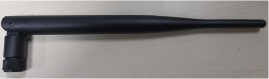
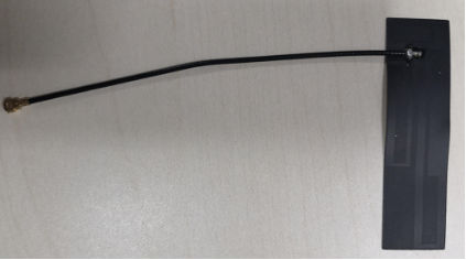
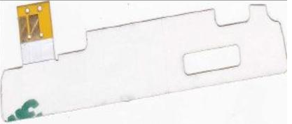
| Antenna type | Antenna provided by the third party (external SMA rod antenna, FPC antenna, etc.) |
TX performance
| Parameter | Minimum value | Maximum value | Unit |
|---|---|---|---|
| GSM850 | -39 | 32.5±2 | dBm |
| GSM900 | -39 | 32.5±2 | dBm |
| DCS1800 | -39 | 30.5±2 | dBm |
| PCS1900 | -39 | 30.5±2 | dBm |
| Frequency error | -15 | +15 | ppm |
RX performance
| Parameter | Minimum value | Typical value | Unit |
|---|---|---|---|
| GSM850 | - | -107.5 | dBm |
| GSM900 | - | -107.5 | dBm |
| DCS1800 | - | -107.5 | dBm |
| PCS1900 | - | -107.5 | dBm |
Antenna
Antenna type
The module does not have its own PCB board antenna, and the third party needs to provide an antenna. The antenna can be an external rod antenna, a spring antenna, an IPEX-FPC antenna, a PCB board antenna, etc. The antenna forms include monopole antenna, PIFA antenna, IFA antenna, loop antenna, etc.
Antenna interference reduction
To ensure optimal GSM/GPRS performance, it is recommended that the antenna be at least 10mm away from other metal parts.
Packaging and production
Mechanical dimensions
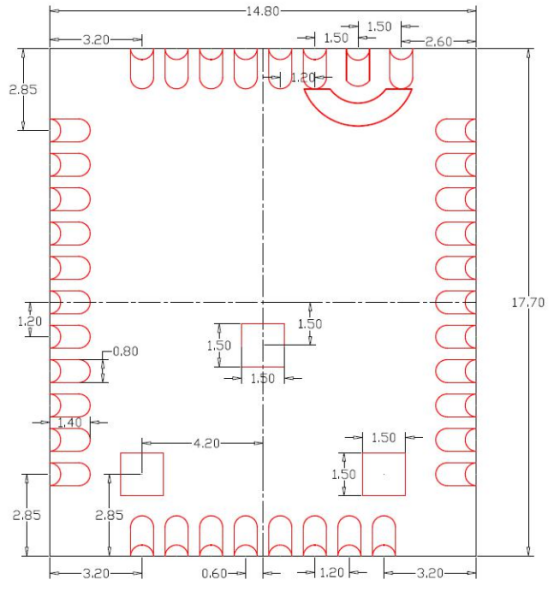
GR4 has 41 pins in total. Among them, 38 pins are LCC package, and 3 pins are LGA package.
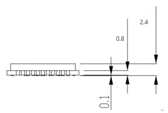
The GR4 dimensions are 17.7±0.35mm (L)×14.8±0.35mm (W) ×2.4±0.15mm (H), which are shown below:
Note: The module length and width tolerance is ±0.35 mm, the height tolerance is ±0.15 mm, and the PCB thickness tolerance is ±0.1 mm.
Side view
Schematic diagram of packaging
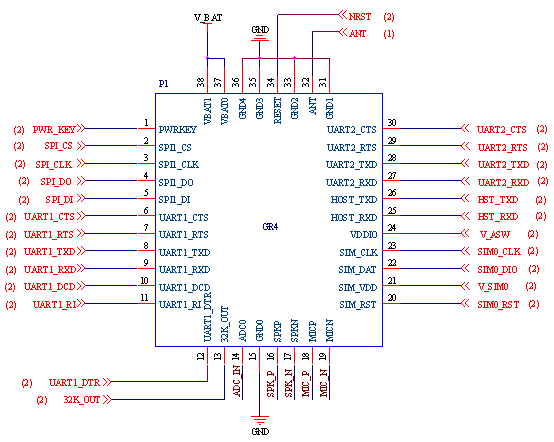
Diagram of PCB packaging-SMT
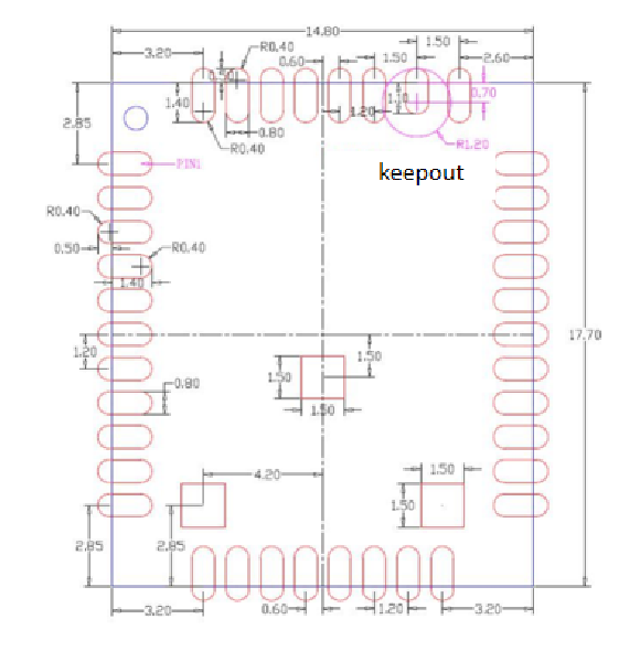
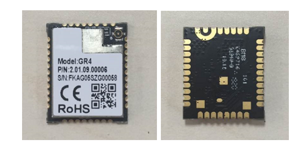
Top/bottom/side view
Production instructions
- The Tuya SMT module should be mounted by the SMT device. After being unpacked, it should be soldered within 24 hours. Otherwise, it should be put into the drying cupboard where the RH is not greater than 10%; or it needs to be packaged under vacuum again and the exposure time needs to be recorded (the total exposure time cannot exceed 168 hours).
- SMT devices:
- Mounter
- SPI
- Reflow soldering machine
- Thermal profiler
- Automated optical inspection (AOI) equipment
- Baking devices:
- Cabinet oven
- Anti-electrostatic and heat-resistant trays
- Anti-electrostatic and heat-resistant gloves
- SMT devices:
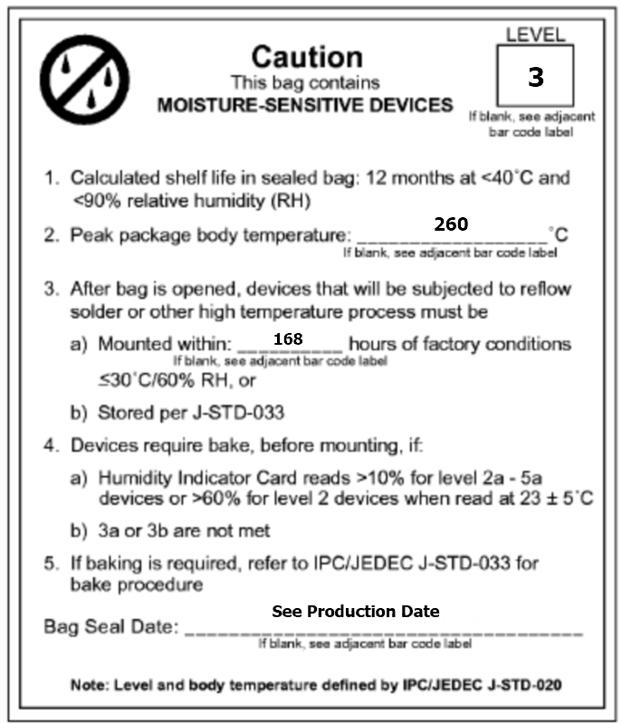
- Storage conditions for a delivered module:
-
The moisture-proof bag must be placed in an environment where the temperature is below 40°C and the relative humidity is lower than 90%.
-
The shelf life of a dry-packaged product is 12 months from the date when the product is packaged and sealed.
-
There is a humidity indicator card (HIC) in the packaging bag.

-
- The module needs to be baked in the following cases:
- The packaging bag is damaged before unpacking.
- There is no HIC in the packaging bag.
- After unpacking, circles of 10% and above on the HIC become pink.
- The total exposure time has lasted for over 168 hours since unpacking.
- More than 12 months have passed since the sealing of the bag.
- Baking settings:
- Temperature: 40°C and ≤ 5% RH for reel package and 125°C and ≤5% RH for tray package (please use the heat-resistant tray rather than plastic container)
- Time: 168 hours for reel package and 12 hours for tray package
- Alarm temperature: 50°C for reel package and 135°C for tray package
- Production-ready temperature after natural cooling: < 36°C
- Re-baking situation: If a module remains unused for over 168 hours after being baked, it needs to be baked again.
- If a batch of modules is not baked within 168 hours, do not use wave soldering to solder them. Because these modules are Level-3 moisture-sensitive devices, they are very likely to get damp when exposed beyond the allowable time. In this case, if they are soldered at high temperatures, it may result in device failure or poor soldering.
- In the whole production process, take electrostatic discharge (ESD) protective measures.
- To guarantee the passing rate, it is recommended that you use the SPI and AOI to monitor the quality of solder paste printing and mounting.
Recommended oven temperature curve
Set oven temperatures according to the following temperature curve of reflow soldering. The peak temperature is 245°C.

-
A: Temperature axis
-
B: Time axis
-
C: Liquidus temperature: 217 to 220°C
-
D: Ramp-up slope: 1 to 3°C/s
-
E: Duration of constant temperature: 60 to 120s; the range of constant temperature: 150 to 200°C
-
F: Duration above the liquidus: 50 to 70s
-
G: Peak temperature: 235 to 245°C
-
H: Ramp-down slope: 1 to 4°C/s
Note: The above curve is just an example of the solder paste SAC305. For more details about other solder pastes, please refer to Recommended oven temperature curve in the solder paste specifications.
Storage conditions
MOQ and packaging information
| Product number | MOQ (pcs) | Packaging method | The number of modules per reel | The number of reels per carton |
|---|---|---|---|---|
| GR4 | 5600 | Tape reel | 1400 | 4 |
Is this page helpful?
YesFeedbackIs this page helpful?
YesFeedback


