IR Hardware Reference
Last Updated on : 2021-04-22 10:20:55Copy for LLMView as MarkdownDownload PDF
The infrared (IR) capability function requires hardware. The hardware includes the IR transmitter circuit and the IR receiver circuit. This topic describes the IR transmitter circuit, IR receiver circuit, recommended device selection, IR board angle, and IR LED angle.
IR transmitter circuit
Circuit diagram
The module connected to the out part corresponds to the IR transmitting I/O port that outputs IR signals to drive the circuit.
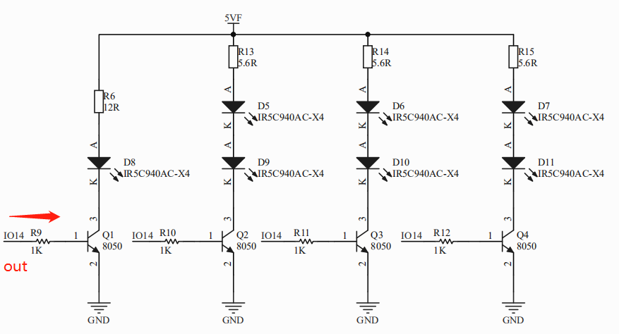
Recommended model
XYC-IR5C940AC-X4. For more information, see the attachment.
IR receiver circuit
Circuit diagram
The module connected to the in part corresponds to the IR receiving I/O port that receives, parses, and analyzes IR signals.
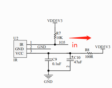
Recommended model
LF0038KAHA. For more information, see the attachment.
IR circuit layout recommendations
- Place the filter capacitor as close to the IC pin as possible.
- The IR LEDs are evenly arranged. It is recommended to place one piece perpendicular to the PCB, and one piece every 60° on the outer ring (30° to 40° with the PCB).
- It is recommended that the current limiting resistor package of the IR LED should not be less than 0805.
- After the power supply filtering is completed, the front surface of the receiver shall be kept away from direct light.
Attachment
Is this page helpful?
YesFeedbackIs this page helpful?
YesFeedbackMarketing Cooperation
Business Cooperation
Customer Service
Media Inquiry


