MCU SDK Porting
The MCU SDK contains all you need to get started with MCU program development, such as functions and sample code. It is automatically generated based on the product features defined on the Tuya Developer Platform. This topic describes how to port the NB-IoT MCU SDK to your project.
Overview
The MCU SDK is automatically generated based on the product features defined on the Tuya Developer Platform. With the built-in support for communication and protocol parsing, the MCU SDK can facilitate interfacing with Tuya’s NB-IoT modules. You can add this SDK to existing projects and complete the required configuration to implement the MCU program development.
Resource requirements
The SDK requirements for the MCU are as follows. If your hardware is constrained in resources, you can refer to functions in the SDK and port the protocol yourself.
- Memory: 4 KB
- RAM: About 100 bytes of RAM are required, depending on the data length of the data point (DP). If you enable OTA updates, it must be greater than 260 bytes.
- Nested function: 9-level.
File structure
| Files | Description |
|---|---|
mcu_api.c |
Contains functions that can be called. |
mcu_api.h |
Contains declarations for functions in mcu_api.c. |
protocol.c |
Contains functions for processing protocol data. You can add code to related functions as needed to get data sent by the NB-IoT module to the MCU. |
protocol.h |
Contains parameters that the MCU sends to the NB-IoT module for initialization, macros defined for custom functions, and declarations for functions in the protocol.c. |
system.c |
Contains the implementation of parsing the serial protocol. |
system.h |
Contains definitions of commands and some global variables, and declarations for functions in system.c. |
nbiot.h |
Contains macro definitions for NB-IoT communication. |
How to port SDK
- Program the MCU and port the SDK.
- Configure the operation mode and cloud connectivity for the product based on
nbiot.h. - Check macro definitions in the
protocol.h. - Port the
protocol.cfile and call functions. - Add the function for DP data communication.
Step 1: Programming and porting
-
In your original project, initialize the MCU peripherals, including the serial port and GPIO (configure the NB-IoT wakeup source).
-
Copy the
.cand.hfiles in the MCU SDK folder to your project directory where other.cand.hfiles are located.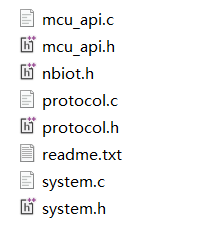
Step 2: Check the parameter configurations in nbiot.h.
- Define the operation mode:
SIM_MODEspecifies the operation mode that can be set topsm,drx, oredrx. The operation mode you set must be the same as that of the product you create on the Tuya Developer Platform. - Define cloud connectivity:
CONNECT_MODEspecifies how the NB-IoT module is connected to the Tuya Cloud. Valid values includeispandtuya. The mode you set must be the same as that of the product you create on the Tuya Developer Platform.isp: The NB-IoT module is connected to the carrier’s cloud and then to the Tuya Cloud.tuya: The NB-IoT module is directly connected to the Tuya Cloud. Currently, this mode applies to China Mobil SIM cards only.
- Configure MCU updates:
SUPPORT_MCU_FIRM_UPDATEspecifies whether to enable MCU updates or file download. You can enable this macro if you need this feature.
Step 3: Check macro definitions in protocol.h
-
Define product ID (PID):
PRODUCT_KEYis the macro defined for the PID. PID is the unique identifier of each product. It can be found on the page of Product Development.If the
PRODUCT_KEYand the PID are inconsistent, you can go to Hardware Development > Download Documents section and download the latest SDK.#define PRODUCT_KEY "ny18le8hpsb3z97g" -
Define MCU version number:
MCU_VERspecifies the software version, which defaults to1.0.0. If you enable OTA updates for the MCU firmware, you need to update the MCU version number after the firmware update is installed.#define MCU_VER "1.0.0" -
Configure clock synchronization:
SUPPORT_MCU_RTC_CHECKspecifies whether to enable clock synchronization with a time server. If your product is time-sensitive, this feature can ensure the RTC of the NB-IoT module is accurate. If you enable this macro, you need to implementmcu_write_rtctimeinProtocol.c.
(Optional) Step 4: Transmit and receive buffer
-
Serial receive buffer: The buffer size depends on how often the serial data handler is called. If the MCU can quickly process serial data, the buffer size can be reduced.
-
Serial transmit buffer: The buffer size must be greater than the maximum length of DP data.
-
Buffer for serial data processing: The buffer size must be greater than the maximum length of DP data. If the OTA update feature is enabled, the buffer size must be greater than the maximum amount of payload.
/******************************************************************************
                        3: Define the transmit and receive buffer:
                    If your MCU has insufficient RAM, you can change the buffer size to 24 bytes.
******************************************************************************/
#ifndef SUPPORT_MCU_FIRM_UPDATE
#define NBIOT_UART_QUEUE_LMT             16              // The size of the data receive queue, which can be reduced if your MCU has insufficient RAM.
#define NBIOT_UART_RECV_BUF_LMT          24              // It depends on the amount of DP data but must be greater than 24 bytes.
#else
#define NBIOT_UART_QUEUE_LMT             128              // The size of the data receive queue, which can be reduced if your MCU has insufficient RAM.
#define NBIOT_UART_RECV_BUF_LMT          300              // It depends on the amount of DP data but must be greater than 24 bytes.
#endif
#define NBIOT_UART_SEND_BUF_LMT          64               // It depends on the amount of DP data but must be greater than 24 bytes.
/******************************************************************************
Step 5: Port protocol.c file and call functions
-
Copy the
nbiot.hfile to the folder where NB-IoT files are stored, such as themain.cfolder. -
Call the
nbiot_protocol_init()function in themcu_api.cfile after the MCU serial port and other peripherals are initialized. -
Specify the serial transmission function in
uart_transmit_outputin theprotocol.cfile, and delete#error.
Example:void uart_transmit_output(unsigned char value) { extern void Uart_PutChar(unsigned char value); Uart_PutChar(value); // Serial transmission function } -
In the interrupt handler for serial data reception, call
uart_receive_inputin themcu_api.cfile and pass in the received data as the parameters.Example:
void USART3_IRQHandler(void) { unsigned char Res=0; if((USART3->SR&UART_FLAG_RXNE) != 0) { Res=USART3->DR; uart_receive_input(Res); } } -
After the MCU runs in the
while(1)loop, it calls thenbiot_uart_service()function in themcu_api.cfile. The sample code inmain.cis as follows:#include "nbiot.h" ... void main(void) { nbiot_protocol_init(); ... while(1) { nbiot_uart_service(); ... } ... }The MCU must directly call the
nbiot_uart_service()function in themcu_api.cfile in thewhile(1)loop. After the program is initialized, if an interrupt service routine (ISR) is necessary, you must keep it as short as possible. Do not call the data reporting function to avoid loss of data.
Things to note
Power saving lock
The NB-IoT module sleeps when it is idle (no data communication) to save power.
If the MCU needs to process a large amount of data and does not want the NB-IoT module to sleep, it can send the power saving lock command to the NB-IoT module to prevent it from sleeping. After data processing is finished, the MCU can send the power saving lock command to the NB-IoT module again to resume the sleep pattern.
If the MCU does not want the NB-IoT module to sleep throughout the operation, it should send the power saving lock command to the NB-IoT module immediately upon receiving the product information query.
Discrete approach
NB-IoT features multi-connection and low power and cost. However, the narrowband imposes a limit on the number of concurrent connections.
-
When you onboard a large number of devices at the same time, you can use the discrete approach to process concurrent requests from NB-IoT devices to achieve overload control.
-
You need to test how the discrete approach works on the MCU side to ensure the effect is as expected.
-
The discrete approach only works for power-on startup. The discrete approach to data reporting should be maintained separately on the MCU side. If the NB-IoT module on your product is designed to be powered off and on frequently, do not use the discrete approach.
/*****************************************************************************
Function name: mcu_set_discrete_info
Function description: Set the discrete approach to the first power-on startup for the NB-IoT module.
Input parameter: en: 0 means to disable the discrete approach. 1 means to enable the discrete approach.
          duration: The maximum duration of random discrete, ranging from 120 to 1,800. For example, if `duration` is set to 150, the random range is 0 to 150.
          step: The step of the discrete range. With the same duration, a smaller step leads to larger discrete.

Return parameter: none
Description:
*****************************************************************************/
void mcu_set_discrete_info(unsigned char en, unsigned int duration, DISCRETE_STEP step)
{
    unsigned int  du = 0;
    unsigned int  length = 0;
    unsigned char uart_buff[128] = {0};

    du = duration;
    if (duration < 120){
        du = 120;
    }
    if (duration > 1800){
        du = 1800;
    }

    length = snprintf(uart_buff, sizeof(uart_buff), "{\"enable\":%d,\"duration\":%d,\"step\":%d}",\
                                                  (unsigned int)en, du, (unsigned int)step);

    length = set_nbiot_uart_buffer(0, uart_buff, length);
    nbiot_uart_write_frame(SET_DISCRETE_INFO_CMD, length);
}
Call DP data communication function
For more information, see MCU SDK Porting for Wi-Fi Protocol.
OTA updates or file download
This section describes how the MCU and the NB-IoT module communicates during OTA updates or file download.
File download works the same way as OTA updates. The logic described in this section also applies to file download.
| OTA update process | Description |
|---|---|
| Initiate OTA updates | When the NB-IoT module detects an MCU firmware update, it will send the MCU a command to initiate an OTA update.
|
| Transmit data | After sending the first packet, the NB-IoT module resends the data if the MCU does not respond within five seconds. If the MCU does not respond after three retries, the OTA update is considered failed.
|
| Data transmission is completed | You can determine whether the OTA transmission is completed in the following two ways.
|
Avoid downloading duplicate data when an update is initiated and installed.
Perform a cyclic redundancy check (CRC) on firmware when an update is initiated to avoid downloading duplicate data.
case MCU_OTA_START_CMD:
...
// Return a response to the module.
    #error "Implement the response to the packet size for transmission and the offset address, and then delete this line"
    /*
      1. Calculate the CRC value (crc32_app) of the firmware that is running.
      2. Compare the calculated value with the firm_crc32 given at the beginning of the update.
      if (firm_crc32 == crc32_app) {
        // If the firmware already exists, download is not needed. The MCU only needs to return the file length.
        mcu_firm_update_start_ack(unsigned char unit_len, firm_length);
      }
      else {
        // The MCU returns the offset address for resumable transfer or returns 0 for download from the beginning.
        mcu_firm_update_start_ack(unsigned char unit_len, unsigned long received_len);
      }
    */
...
break;
If the update installation is repeated, compare the firmware CRC to detect duplicate data.
/*****************************************************************************
Function name: mcu_firm_update_handle
Description: The MCU enters update mode.
Input parameters: value indicates the firmware buffer.
           position: Indicates where the packet is located in the firmware.
           length: The length of the current update package. When the length is zero, the transmission is completed.
Return parameter: none
Description: This function is intended to be implemented by you.
*****************************************************************************/
unsigned char mcu_firm_update_handle(const unsigned char value[],unsigned long position,unsigned short length)
{
  #error "Complete the implementation for OTA MCU update and then delete this line."
  if(length == 0)
  {
    // Transmission of updates is completed.

    #error "Follow the steps below to perform CRC32 checks and return the result of 0 or 1. Delete this line after you implement the code."
    /*
      1. Calculate the CRC value (crc32_app) of the downloaded firmware.
      2. Calculate the CRC value (crc32_app) of the firmware that is running.
      3. Compare the calculated value with the CRC32 value given at the beginning of the update.
      if (crc32 == crc32_dl) {        // The firmware is downloaded. Navigating to the latest firmware.
        mcu_firm_update_data_ack(1, 0);        // CRC check passed.
        // Navigate to the required application.
      }
      else if (crc32 == crc32_app){        // The latest firmware is running. The MCU returns a response.
        mcu_firm_update_data_ack(1, 0);        // CRC check passed.
      }
      else {
        mcu_firm_update_data_ack(1, 1);        // CRC check failed.
      }
    */

  }
  else
  {
    //mcu_firm_update_data_ack(0, 0);

    // Process the firmware.

  }

  return SUCCESS;
}
Is this page helpful?
YesFeedbackIs this page helpful?
YesFeedback


