NB-IoT Common Solution
Narrow Band Internet of Things (NB-IoT) is built in a cellular mobile communication network to realize thing-to-thing communication and thing-to-person communication. NB-IoT focuses on the low-power wide-area (LPWA) Internet of Things (IoT) market and is an emerging technology that can be widely used around the world.
Background information
NB-IoT network consumes only about 180 kHz bandwidth and uses the licensed band. It can coexist with the existing network in three deployment modes, including in-band, protection band, or independent carrier wave. NB-IoT network can be directly deployed in a GSM network, a UMTS network, or an LTE network to reduce the deployment cost and realize a smooth upgrade.
NB-IoT features
-
Low power consumption
The installation environment of IoT applications, such as intelligent meter reading, environmental monitoring, and intelligent agriculture, has no power supply and requires batteries. In order to meet the requirement of 5 to 10 years of battery life, the introduction of PSM and eDRX technology to the NB-IoT network greatly reduces the terminal power consumption. The device is in extremely low power consumption status during most of the life cycle, thus ensuring the service life of the battery.
-
Low cost
NB-IoT terminal adopts narrow-band technology with a less complex baseband. It only uses a single antenna, adopts half-duplex mode, and low-cost RF modules. Most unnecessary functions, such as SRVCC, IMS, emergency call, and other functions, can be cut. At the same time, the SoC built-in power amplifier (PA) is adopted, so that the requirements for the terminal flash storage space, terminal size, and terminal radiofrequency are reduced. The terminal cost of the NB-IoT is greatly reduced.
-
Large connection
NB-IoT has 50 to 100 times higher uplink capacity improvement (specific service model) than 2G, 3G, and 4G. NB-IoT provides 50 to 100 times of access compared with existing wireless technology. A single community can support 50,000 users.
-
Broad signal coverage
With 164 dB maximum coupling loss (MCL), NB-IoT improves 20 dB gain compared with GPRS. NB-IoT provides better coverage in underground garages, basements, underground pipelines, and other places where signals are difficult to reach.
| Feature | NB technical feature | Value range |
|---|---|---|
| Small amount of data | Limited air interface resources (180 kHz), suitable for small data communication | 50 bytes to 200 bytes is appropriate, the smaller the better |
| Low frequency, long period | Most terminals should be in hibernation status for a long time, with a low frequency of reporting data | Report on a daily basis, and 1 to 2 times a day is appropriate. High-frequency reporting (such as every 30 minutes) occupies a large amount of network capacity. The higher the reporting frequency, the greater the impact on network capacity. |
| Low power consumption | PSM mode of NB network has the lowest power consumption | The first-choice for applications that are sensitive to power consumption |
| Low mobility | NB is suitable for slow movement | Moving speed is less than 30 km/h |
| Deep coverage | NB coverage capacity is relatively good | Support scene coverage such as basement |
| Low rate | The theoretical upstream peak rate is 15.6 Kbit/s and the theoretical downstream peak rate is 21.25 Kbit/s | Large-rate bandwidth type service cannot be carried by NB |
NB-IoT network architecture
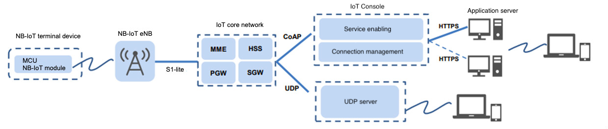
NB-IoT network consists of NB-IoT terminal, NB-IoT base station, NB-IoT Packet Core Network, IoT connection management platform, and industry application server. The access network architecture of NB-IoT is the same as that of LTE.
NB-IoT power-saving mode
The development of the NB-IoT service scale is closely related to the carrier service model. Its applicable scene is the applications with "small traffic, mainly reporting, long-term hibernation, sensitiveness to power consumption, and low mobility". In order to carry a large number of low-power devices in the NB-IoT network, the most important technologies are PSM and eDRX.
NB-IoT supports three power saving modes: PSM (power saving mode), DRX (discontinuous reception mode), and eDRX(extended discontinuous reception mode).
-
PSM mode
The terminal is in deep hibernation during the non-service period and does not receive downstream data. Only when the terminal actively sends mobile original data (MO data), the downstream data cached by the Developer Platform can be received.
In this status, the radio frequency of the terminal is turned off, which is equivalent to a shutdown status. However, the core network side still retains the user context, and the user does not need to attach PDN establishment when entering the idle status or connected status.
It is suitable for services without delay requirement on downstream data. A terminal device has low power consumption and adopts battery power supply mode, such as meter reading service.
-
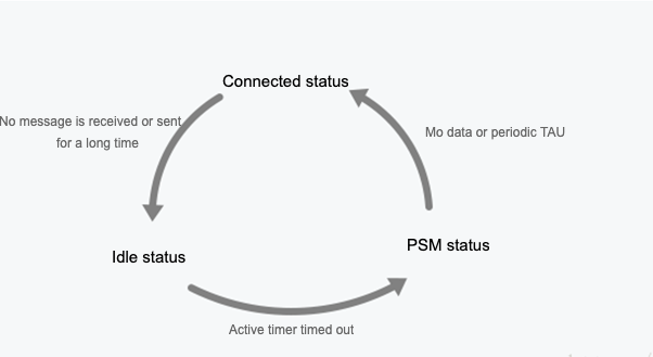
Active: the module is active, all functions are normally available, and data can be sent and received. In this mode, the module can switch to the idle mode or PSM mode.
-
Idle: the module is in the light sleep status and network connection status, and can receive paging messages. In this mode, the module can switch to the active mode or PSM mode.
-
PSM: the module is in the deep sleep status, and only RTC works. The module is disconnected from the network, and cannot receive paging messages. When the timer times out, the module is woken up. The module can also be woken up by pulling down the PSM_EINT pin.
-
-
eDRX mode
The terminal device takes into account the services with low power consumption and certain delay requirements. In each eDRX cycle, the terminal can receive downstream data only in the set paging time window. The terminal is in hibernation status for the rest of the time and does not receive downstream data. This mode can strike a balance between downstream traffic delay and power consumption, such as remotely shutting down gas supply.
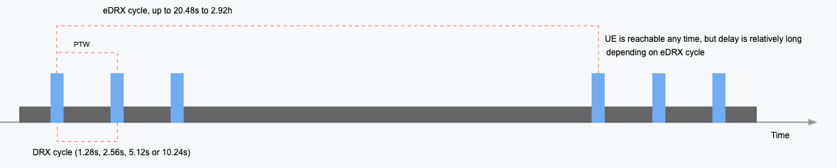
In each eDRX period, there is a paging time window (PTW). The terminal monitors the paging channel according to the DRX cycle, in order to receive downstream data. DRX cycle time is short, and it can be considered that the terminal does not hibernate and can be reached all the time. The terminal is in a hibernation status for the rest of the time. In the eDRX mode, the terminal device is accessible at any time, but the delay is longer depending on the eDRX cycle configuration. This mode can strike a balance between low power consumption and delay.
-
DRX mode
It can be considered that the downstream service can reach the terminal device at any time. In each DRX cycle, the terminal detects whether the downstream service arrives. This mode is suitable for the service with high requirements for the delay. Terminal devices generally adopt power supply, such as street lamp service.
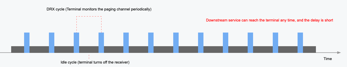
The DRX cycle is short, 1.28, 2.56, 5.12, or 10.24 seconds. The DRX cycle is determined by the operator’s network settings — handling APN service with a SIM card. It can be considered that the downstream service can be reached at any time with a small delay. It is suitable for services with high requirements for the delay, but the power consumption is relatively high. The terminal device generally is powered by mains electricity.
NB-IoT delay
First network access delay: after the NB terminal is powered on, the terminal and the network have lots of message interactions, including authentication, channel establishment, and IP address allocation. It takes 6 to 8 seconds to complete the network access, and obtain the IP address for later data transmission.
Data reporting and receiving delay: after the NB terminal is successfully accessed, when the terminal has data transmission, the terminal will actively establish a wireless connection with the base station. At this time, authentication, IP address allocation, and other processes are no longer required. After the wireless link is successfully established, the data will be sent immediately. The delay of data reporting by the terminal is closely related to the status of the terminal and the wireless network coverage.
| Terminal reports data | Platform sends data (PSM) | Platform sends data (DRX) | Platform sends data (eDRX) |
| Air interface delay + delay between private network and client server | Air interface delay + delay between private network and platform + maximum PSM hibernation cycle (maximum 310 hours) | Air interface delay (750 ms) + DRX paging cycle (maximum 10.24 seconds, minimum 1.28 seconds) | Air interface delay (750 ms) + eDRX paging cycle (maximum 2.92 hours, minimum 5.12 seconds) |
| Second level (3 seconds to 30 seconds) | Hour/day level, depending on terminal reporting cycle | Second level, depending on DRX paging cycle | Second to hour level depending on the eDRX paging cycle |
Key parameters of NB-IoT service acceptance
From the above, it can be seen that the low-power consumption mechanism of the NB application is inseparable from the configuration of SIM card operators. Therefore, when purchasing a SIM card, make clear the APN service you handle. Different APNs are suitable for different application scenes.
Consult Tuya staff when you do not know how to choose APN service.
NB-IoT power consumption
| Terminal status | Power consumption | Measured results of an environment |
|---|---|---|
| PSM status | 3 uA | 2.7 uA |
| eDRX idle status | xxuA to 2 mA | 1 mA |
| DRX idle status | 1 to 4 mA | 1 mA |
| Connection status | Sends 200 mA, and receives 65 mA | Sends 189 mA, and receives 161 mA |
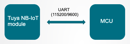
Introduction to MCU general connection solution
When the product functions are complex or the SoC solution cannot meet the requirements, you can choose the MCU connection solution.
In this solution, Tuya module is only used as a data transmission channel. MCU connection solution is often used for large and small household appliances, security sensors, and other categories of products.
Benefits: compared with the common AT instruction development mode of NB-IoT modules on the market, Tuya NB-IoT general connection serial port protocol mode is more beneficial. The development threshold of customers is lower, the maintenance is simple, and new products can be connected more easily.
Firmware type selection
- PSM general firmware — monitoring reporting service scene
- DRX general firmware — sending control service scene
- Other custom firmware — general custom service scene
Tuya now has NB modules that connect MCU, including PSM general module and DRX general module. eDRX general module has not been developed yet. In case of special needs, such as protocol customization and function customization, you can consult Tuya staff to confirm the feasibility of the solution.
Development process
The whole development process consists of product creation, hardware debugging, software development, and function debugging.
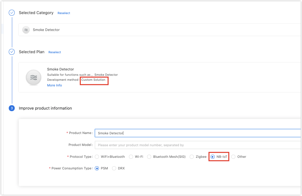
Step 1: Create products
-
Log in to the Developer Platform and create a product. Select the desired product, select NB-IoT for net pairing mode, and select power consumption type according to the product features.
- Select PSM for products with battery power supply and monitoring reporting service.
- Select DRX for products that are insensitive to power consumption and have the sending control services. Note that power consumption selection will be related to the sample sending and production of subsequent modules.
-
After finishing creation, select the functions, panel, module, and firmware based on your product, and download the MCU development documents accordingly.
You can find the specific description of creating products in the MCU connection solution. See Product creation.
Common module
The platform recommends the common module models when you create a product. Here is an example of the NM1 module, which is mostly used in the NB-IoT general solution.
After selecting the module model, you can purchase the module sample online. The hardware engineer will proceed with the board layout design. See the documentation related to hardware development in the documentation center.
Datasheet: NB-IoT Module Datasheet
Hardware design guide: NM1 hardware design
PCB documentation: Common module package library
Note: the peak working electric current of NB-IoT common modules is more than 300 mA. Reserve the electric allowance during power design.
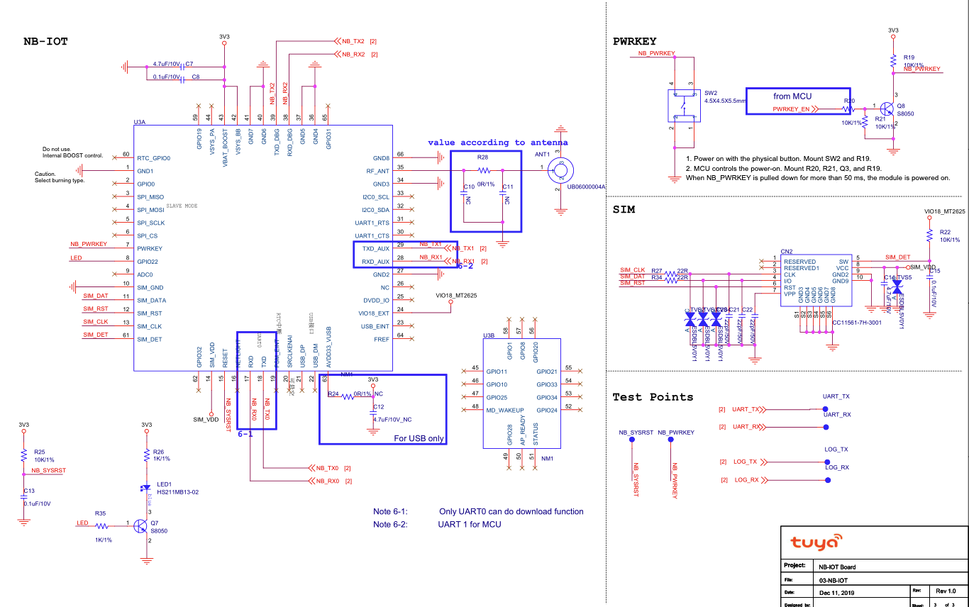
Establish the minimum system of hardware
-
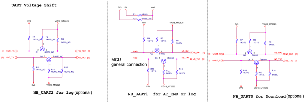
Serial communication circuit: electrical level 1.8V, level conversion required.
- UART0 (optional): module firmware burning pin, which is generally not used in the solution connection process. This I/O pin can be led out to the test point for easy debugging. Baud is 115200.
- UART1 (required): universal connection pin, used for serial communication between the module and the user chip. Baud is 115200 or 9600.
- UART2 (optional): log printing pin. If problems are found in the connection process, this pin is used for collaborative judgment by obtaining the log. This I/O pin can be led out to the test point for easy debugging. Baud is 921600.
-
Module wake-up circuit:
-
Power-on wake-up pin: PWRKEY
-
Low power wake-up pin: PSM_EINT
-
-
SIM card circuit: before design, determine the need for SIM card packaging, USIM or eSIM. Purchase the SIM card of relevant services according to the product features.
-
Power supply circuit: the peak power consumption of the module is about 300 mA, so the power supply circuit shall be properly designed.
-
Antenna circuit: for the antenna radio frequency circuit, see the hardware design manual. The antenna needs to be matched by the antenna manufacturer.
Step 2. Binding verification
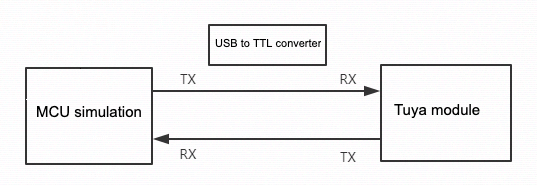
When receiving the module, it is suggested that, before you start coding, you run the provided module debugging assistant to check if the module can work properly. In MCU simulation mode, connect the module and configure the network for practice. Meanwhile, you can get familiar with the protocol interaction process, which will help you to proceed with development debugging.
In MCU simulation mode, the debugging assistant simulates the MCU to automatically respond to the module with the correct protocol data. After you bind the module through the app, you can test DP data reporting and sending. The procedure of operating the assistant and module network configuration is as follows. Before the operation, you need to learn about the operation instruction of the Tuya module debugging assistant. For beginners, see Module Debugging Assistant Instruction.
-
According to the schematic diagram of a minimum system, build the peripheral circuit of the module, make sure that the power supply is stable, the antenna complies with the standard, signal strength is good, and the NB special IoT SIM card is plugged in.
-
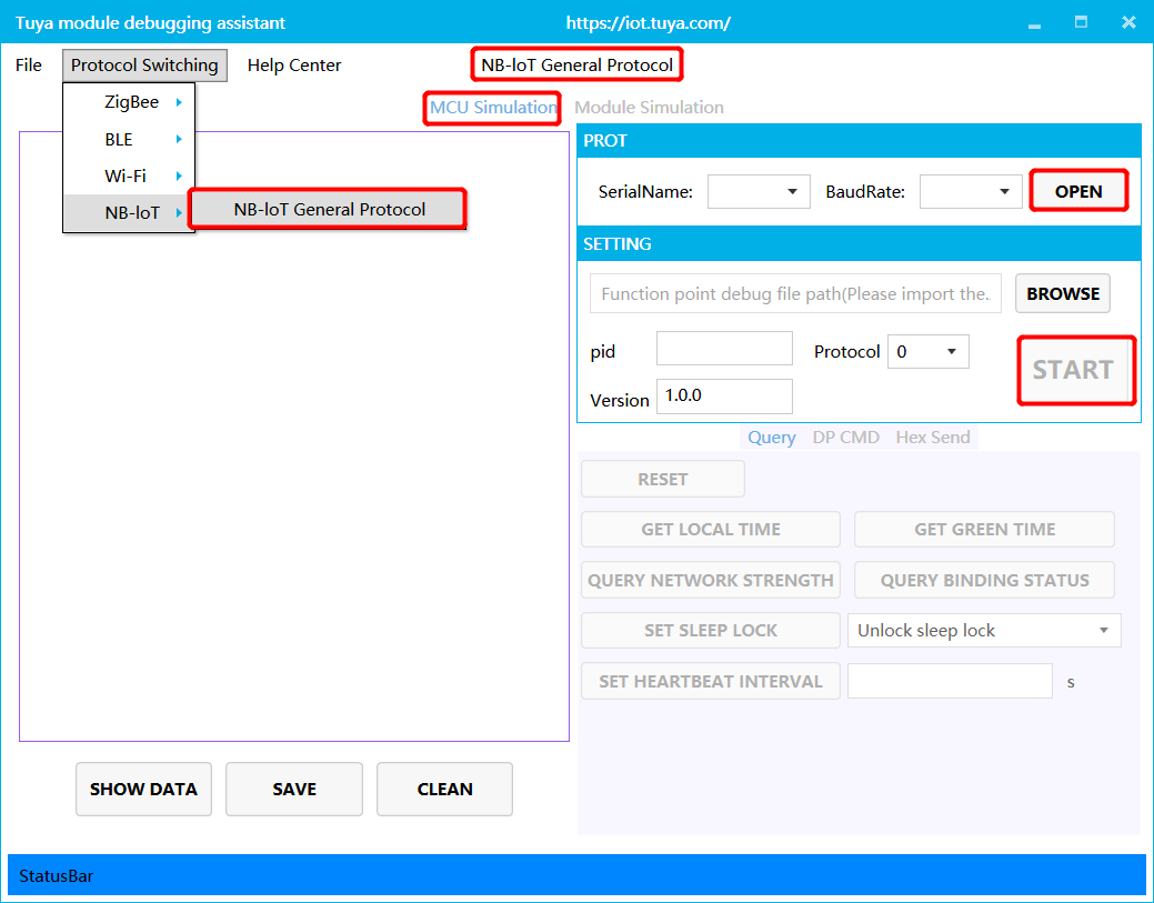
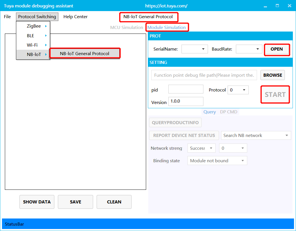
Open the debugging assistant in the development documents, and import the debugging file. Select the NB-IoT general protocol and MCU simulation mode.
-
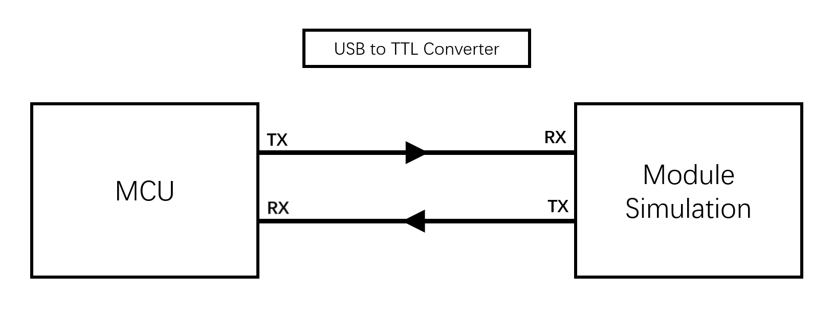
Connect the module serial port to the computer through USB-to-TTL adapter, and select the corresponding serial port and Baud in the assistant. After you open the serial port and click Start, you will see the initial protocol interaction between the module and the host.
Note: after power on, the NB-IoT module will constantly send commands to query the product information. When receiving the correct response, it will proceed with the initial protocol interaction. If the module does not send data after power on, check if the peripheral circuit of the module is correct.
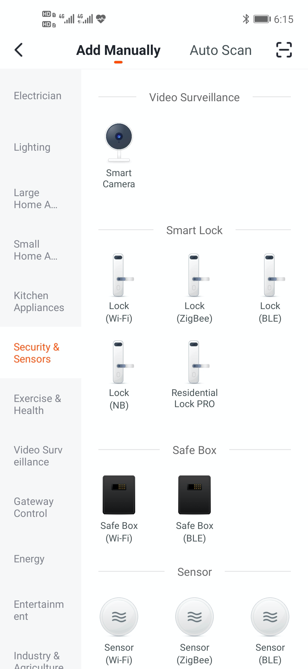
Scan QR code with the app and bind the module
-
Register: after the NB-IoT module is authorized by Tuya, Tuya Cloud will pull module information and register the module on the telecom Developer Platform.
-
Activation: after the NB-IoT module is powered on for the first time and the initialization is completed, it can be connected to the telecom Developer Platform for activation, subject to the network status issued by the module.
-
Use: only modules that have been activated and are not bound by other accounts can be successfully bound by the app.
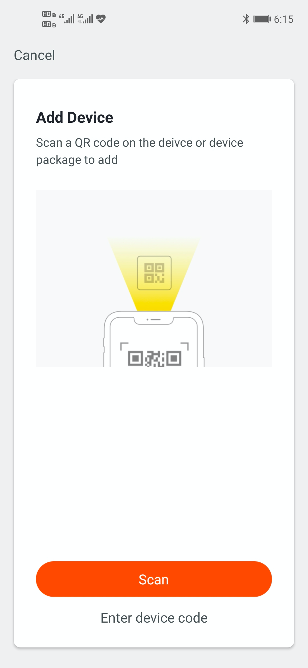
Note: NB-IoT QR code needs to be generated by Tuya production printing tools. For more information, contact Tuya staff.
Step 3: Software development
During hardware debugging, you will see a sequence of serial port protocol interaction data between the module and MCU. To understand this data, refer to the protocol documentation in the development documents. The protocol consists of a basic protocol and function protocol. The basic protocol is product-neutral and shared by the modules. It consists of a module initial command and certain extension function command. The function protocol works to report and send commands based on the basic protocol and specifies the DP data format. The basic protocol is updated in real-time in the documentation center. See Universal Serial Port Protocol of NB-IoT Module.
There are two methods to connect the MCU to Tuya module protocol, migrating MCU SDK, or connecting the protocol by yourself.
Connect the protocol by yourself
If the MCU resource is limited or migrating MCU SDK is inapplicable, you can connect the protocol by yourself.
Migrate MCU SDK
If the MCU resource is sufficient, it is recommended to directly migrate MCU SDK, which facilitates the development process. MCU SDK in the development documents is the protocol application code in C language, and it can be directly imported to the MCU project. MCU SDK requirements for MCU hardware resources: 4 KB Flash, about 100 bytes of RAM. RAM is related to DP data length. A 9-level nested function is adopted. If the resource is limited, you can connect the protocol by yourself. The functions in the SDK package can act as references.
MCU SDK migration tutorial: MCU SDK Migration
Step 4: Protocol verification
After migrating to MCU SDK, you can use the module debugging assistant in module simulation mode to verify the code. The operation is similar to the MCU simulation mode. In the module simulation mode, the assistant automatically sends the initial interaction process to verify whether the MCU response is correct. Prompts will be sent in case of data error. After the initialization interaction is passed, you can manually click other extension functions for testing. After function verification is completed, you can connect the actual module to configure the network and carry out joint debugging.
Note: the module simulation mode only verifies the MCU serial port protocol, and does not support networking.
Step 5: Joint debugging
After the assistant verifies the code, connect the MCU to the module, and configure the network on the app. You will enter function joint debugging. Joint debugging is used to test whether the DPs reporting and sending work properly. The links of useful tools adopted in the debugging are as follows:
Query the background log: log in to the Developer Platform and enter Operation center to query device background log.
Online support center: Tuya provides online support services. If the documentation cannot solve your problems, raise your questions online and our technical team will help you troubleshoot problems.
FAQ: learn about the frequently asked questions during development.
Is this page helpful?
YesFeedbackIs this page helpful?
YesFeedback


