Create a No-Code Seven-Outlet Power Strip
This topic describes how to create a power strip product with a no-code solution on the Tuya Developer Platform, using a Wi-Fi and Bluetooth LE combo seven-outlet power strip as an example.
Create a power strip product
Procedure
-
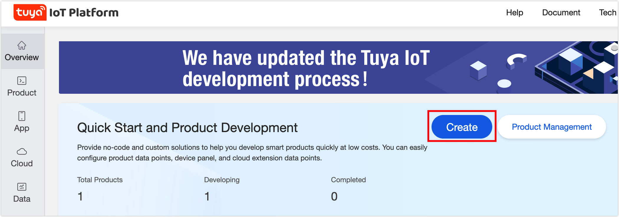
Log in to the Developer Platform.
-
Click Create.
-
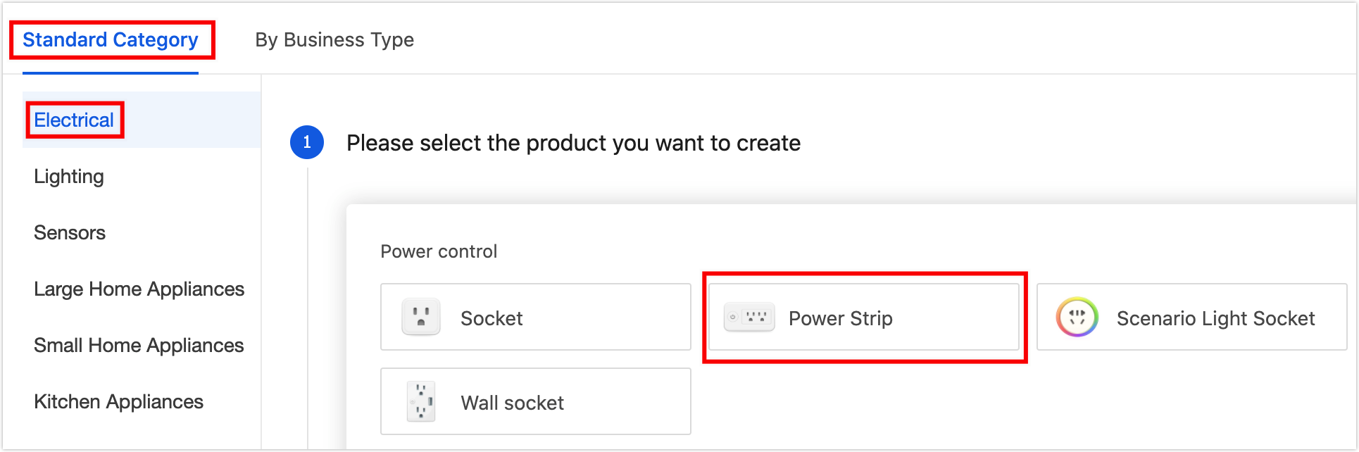
Find Standard Category, and click Electrical > Power Strip.
-
Find Choose a product plan, and click Zero-Coding Development > WiFi+Bluetooth > 7 Outlets > Seven-way Socket(Upgraded)_Wi-Fi_Bluetooth LE.
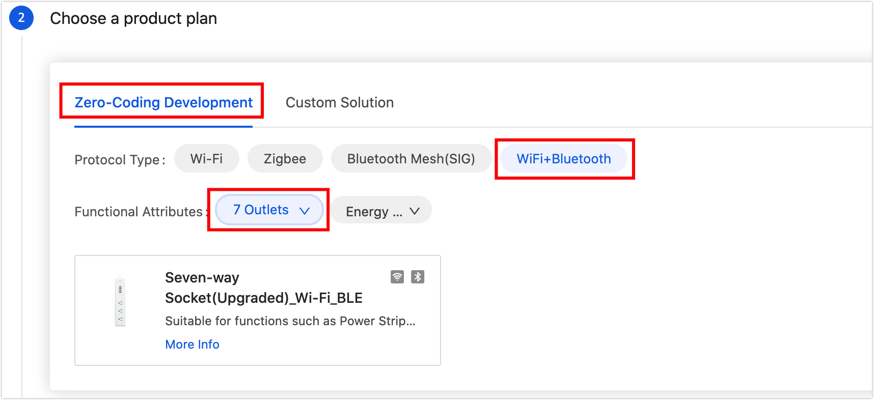
Note: If the functions provided by the no-code solution fails to meet your requirements, you can turn to custom solutions with the reference of SoC custom firmware process.
-
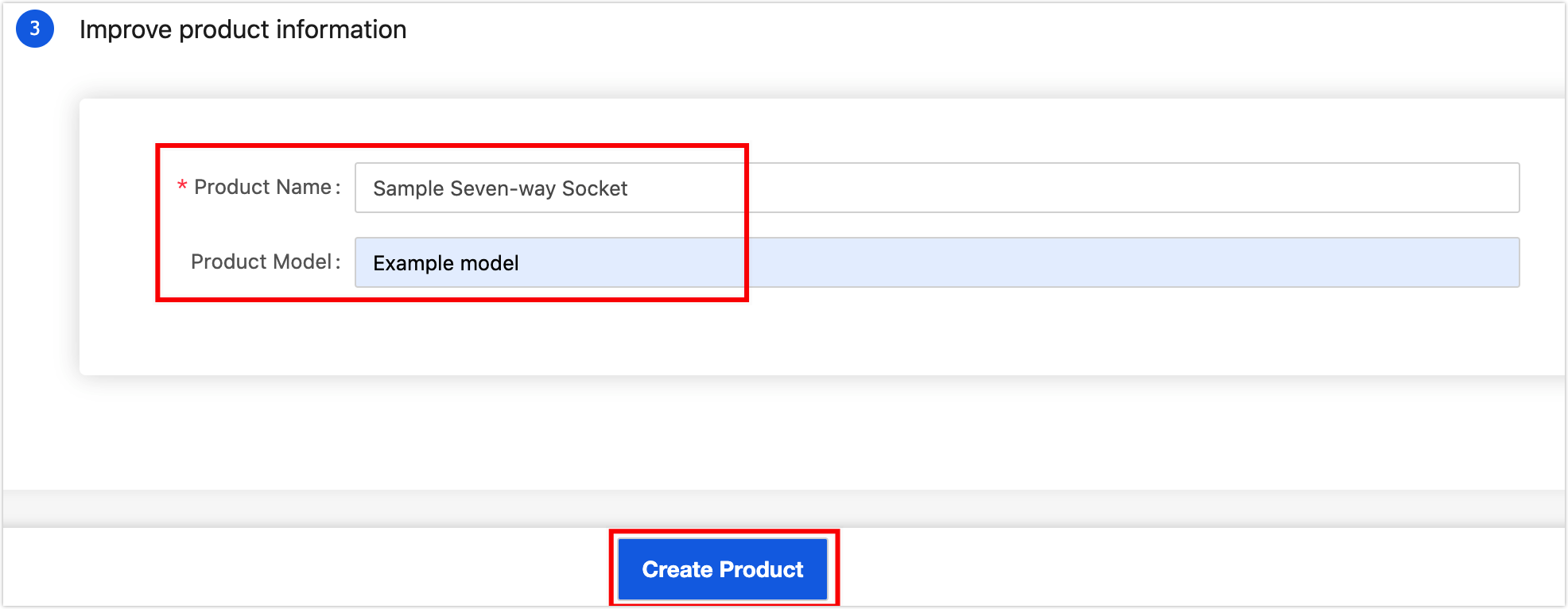
Complete product information.
- Product Name (required): Enter the brand and product name. The name will be displayed on the app control panel.
- Product Model (optional): Enter the product model. Multiple models are available, separated by a comma.
Note:
- The model will not be displayed on the app. It is recommended to enter the internal model name or customer’s product model to ease product and order management on the Developer Platform.
- The product information above can be modified in subsequent steps. See Modify product information.
-
Click Create Product. When a product is created, you will see Create Standard Functions of the step of Function Definition.
Define product features
Procedure
-
In the dialog box of Create Standard Functions, add functions as needed, and click Confirm.
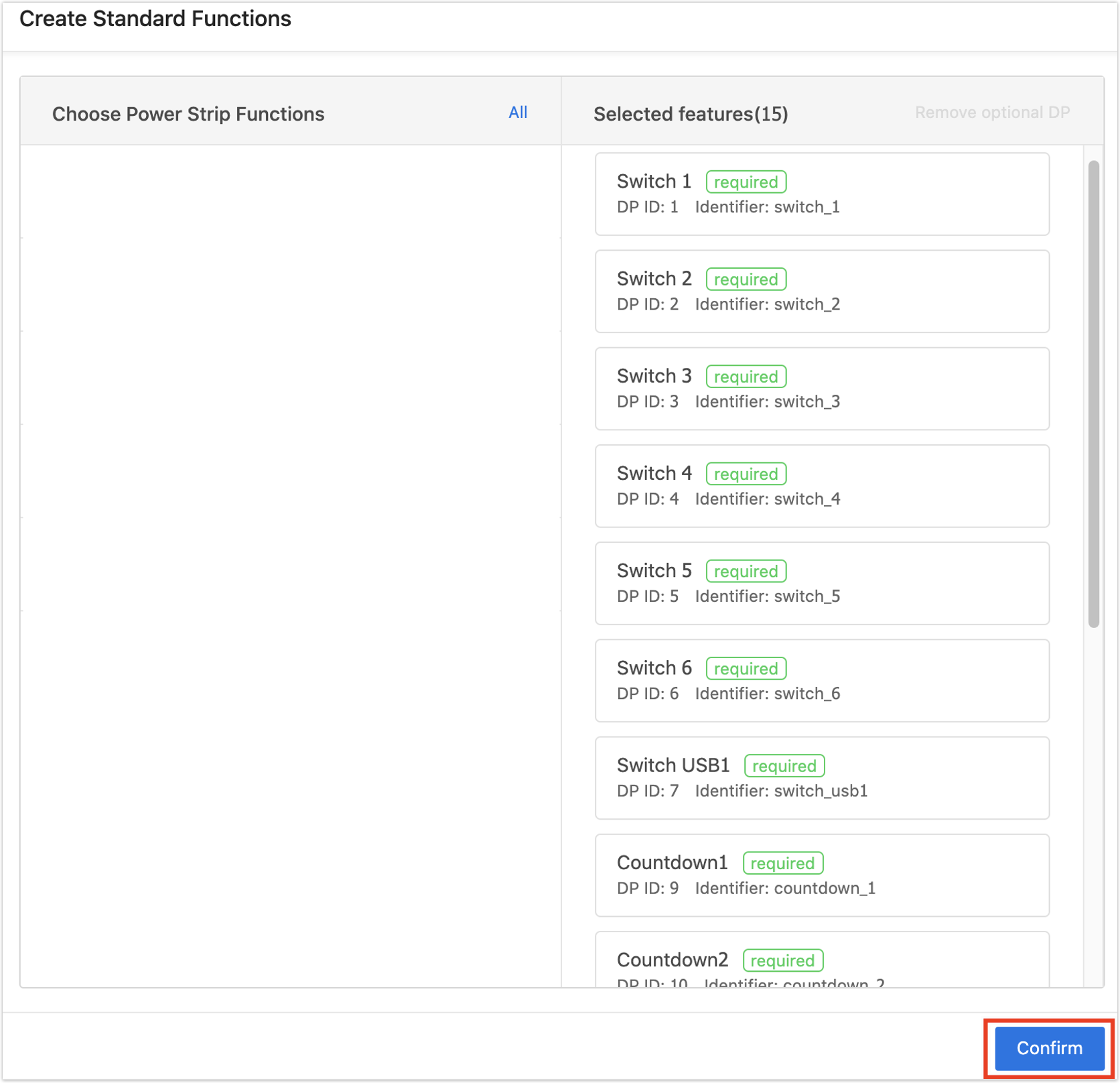
Note:
- The required functions cannot be removed from the selected functions.
- Select data points for different products according to actual interface prompts.
-
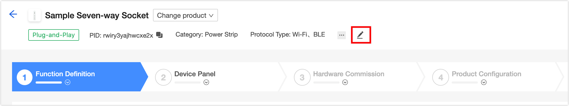
(Optional) Modify product information. Product information can be modified at any stage of the no-code solution.
-
(Optional) On the Function Definition page, enable cloud functions as needed.
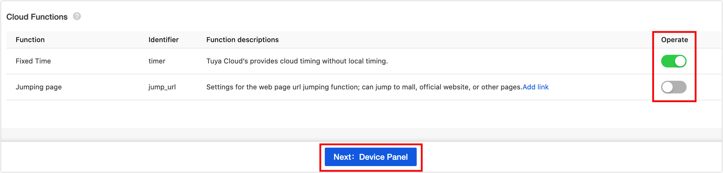
-
Click Next: Device Panel at the bottom of the page. You will see the Device Panel page.
Configure device panel
This section describes how to configure a device panel, using a public panel as an example. If you require custom panels or panel editing, you can proceed with relevant operations as per the prompts.
Procedure
-
On the Device Panel page, find an ideal panel and click Apply.
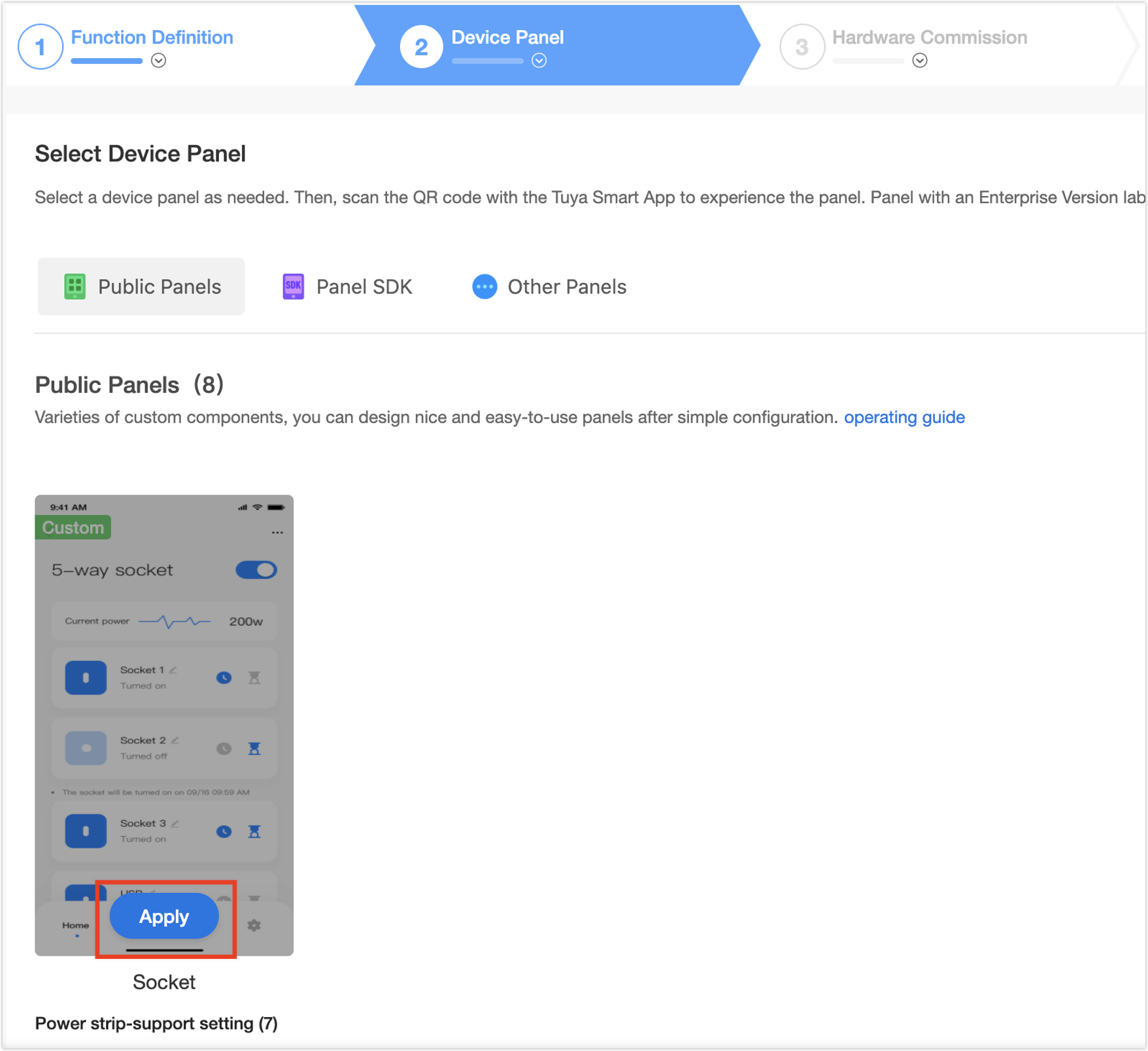
Note: More panels are available after upgrading to an enterprise account.
-
(Optional) You can change or edit the panel as needed. Scan the QR code with the Tuya app to preview.
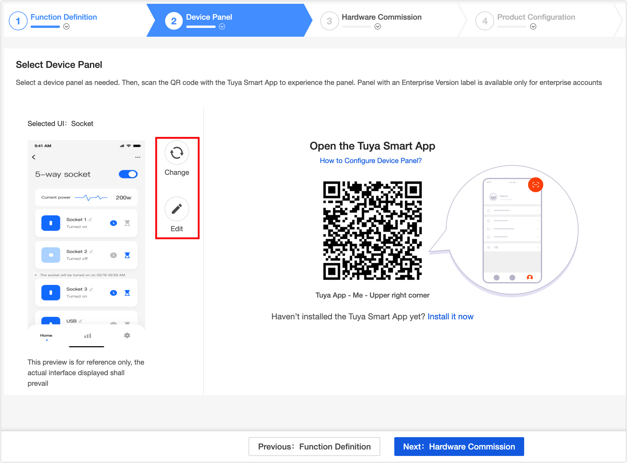
-
Click Next: Hardware Commission. You will see the Hardware Commission page.
Hardware commission
This section uses the WB3S Wi-Fi and Bluetooth LE combo module to describe hardware commission. It is recommended that professional engineers perform hardware commissioning.
Note
- The modules will be burned according to the firmware parameters in the following steps, and the modules can not be changed after being sent.
- If you change the firmware configuration parameters after the module is sent, the two modules will be inconsistent. The old product cannot be upgraded online.
Procedure
-
Select a module as needed after checking the module details.
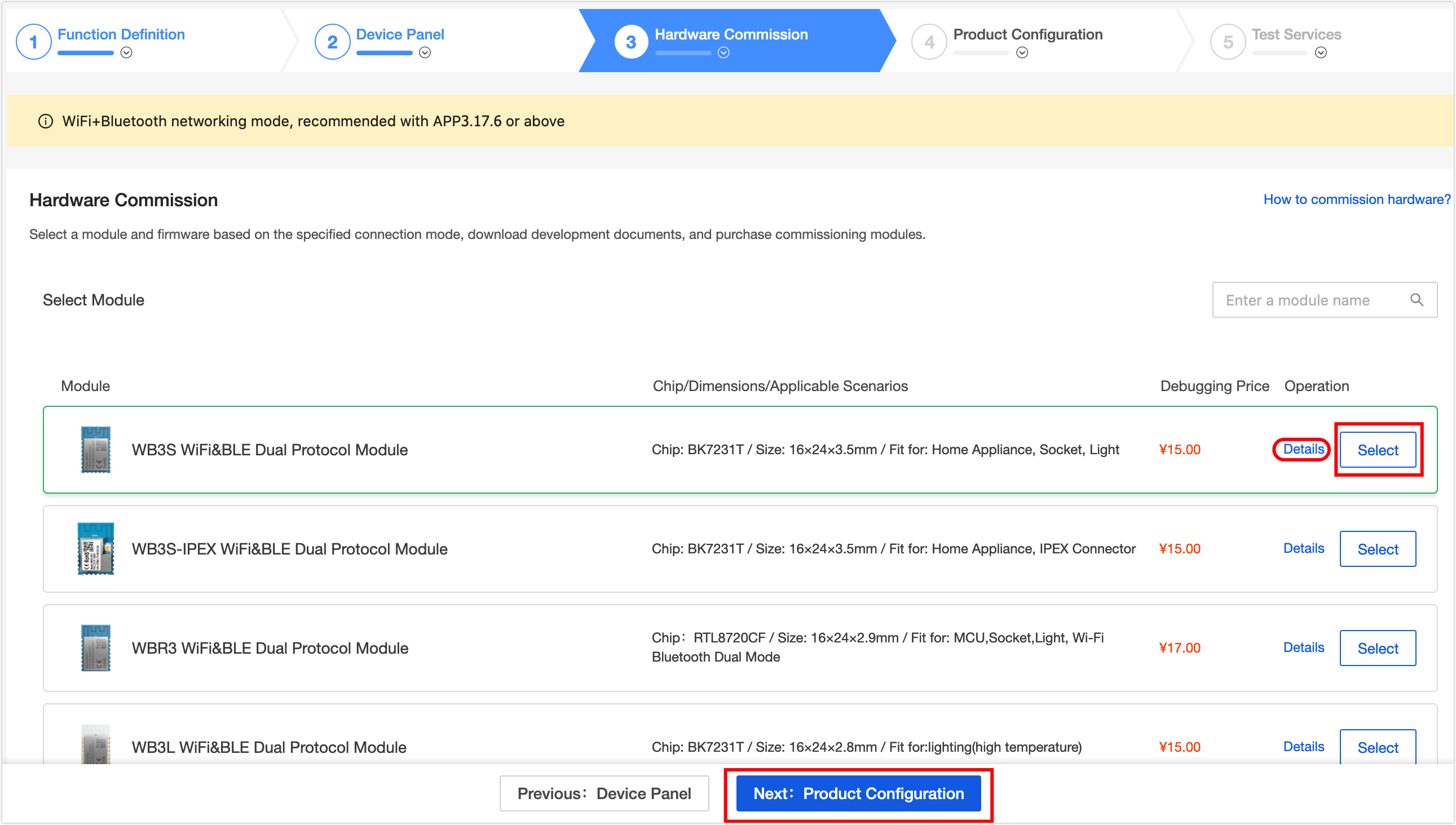
-
Configure firmware parameters in the Generate firmware 1 To be generated area. The specific parameter configuration is as follows.
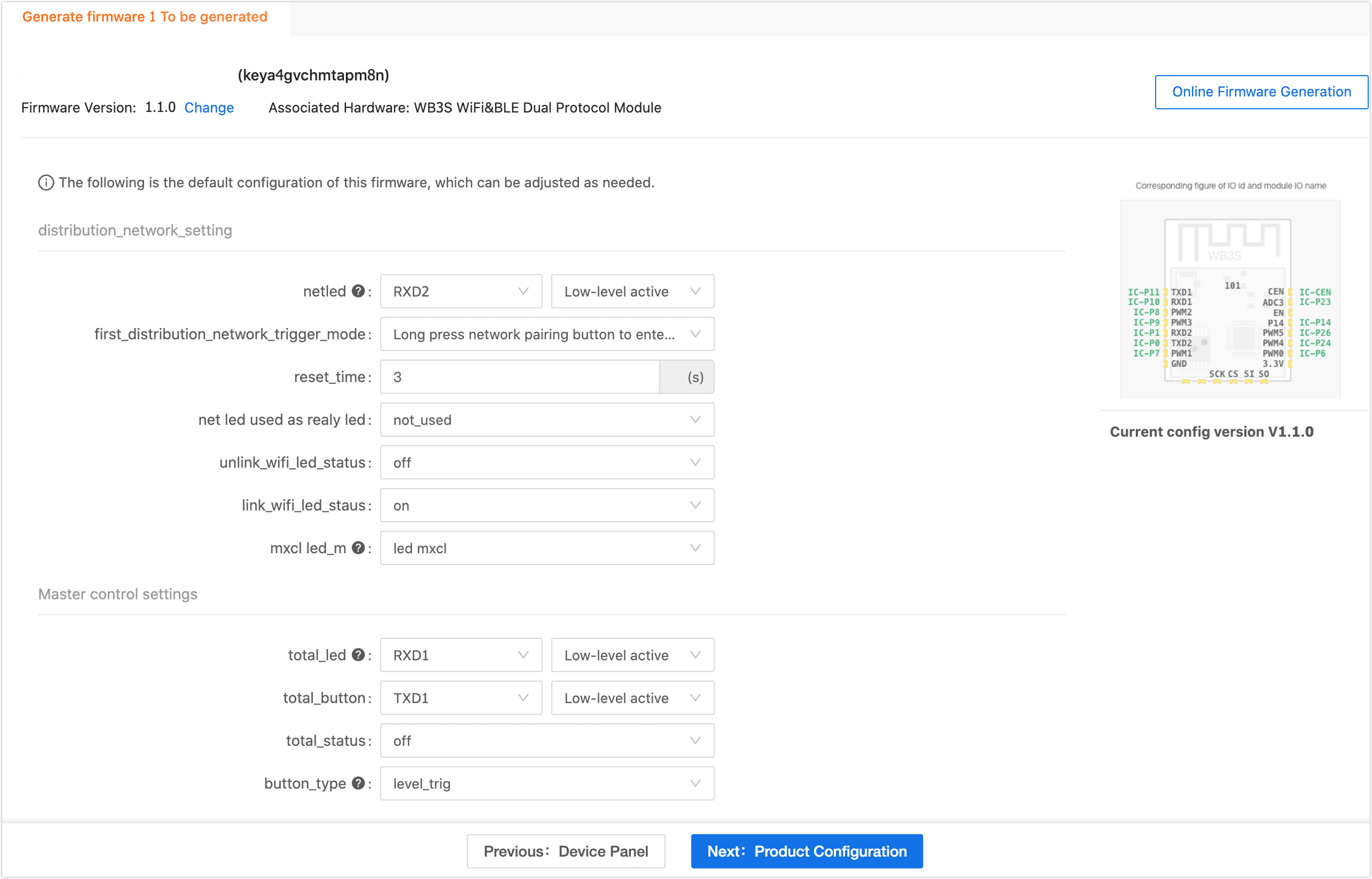
Parameter Type Parameters Description distribution_network_setting netled Select a pin from the pull-down menu and the selected one cannot be used for other parameter configurations. Note: When you set the indicator I/O port, it is recommended to add a pull-up and pull-down resistor of 1–3.3k.
first_distribution_network_trigger_mode Pairing triggering mode when the socket is powered on for the first time. - Start continuous fast flash when initially power on, no re-link logic included: The indicator keeps blinking upon the first time pairing after power-on. The relink logic is not included.
- Long press network pairing button to enter fast flash pairing status for 3 mins, re-link logic included: Press the pairing button until the indicator starts blinking, which indicates that the pairing is ready to start. The relink logic is included.
- Start fast flash when initially power on for 3 mins, re-link logic included: The indicator keeps blinking upon the first time pairing after power-on, which indicates that the pairing is ready to start. The relink logic is included.
Note: With the 3-minute timeout relink function, when a device is locally reset, if it is not paired by another account in 3 minutes, it will retain all the configuration information of the previous account. Otherwise, it will be paired as a new device. If you want to remove pairing information of this device from the account, you can use the app, including Tuya Smart, Smart Life, and OEM app, to remove the configuration or restore factory defaults.
reset_time The time of pressing and holding the button to restore the device.
Value range: 3 to10 seconds.net led used as realy led Select as needed. unlink_network_led_status Select the Wi-Fi indicator status as needed when it is not connected to the network. link_network_led_status Select the Wi-Fi indicator status as needed when it is connected to the network. mxcl led_m In terms of simultaneous lighting of dual-color indicators. - no led mxcl: Only the power indicator is on, without mixing.
- led mxcl: The power indicator and network indicator can be turned on simultaneously, with mixing.
Master control settings total_led Select a pin from the pull-down menu and the selected one cannot be used for other parameter configurations. High-level active and low-level active. Note: When you set the indicator I/O port, it is recommended to add a pull-up and pull-down resistor of 1–3.3k.
total_button Select a pin from the pull-down menu and the selected one cannot be used for other parameter configurations. High-level active and low-level active. total_status - Power off: Each time the device is powered on again, the relay is off.
- Power on: Each time the device is powered on again, the relay is on.
- Power off memory: Each time the device is powered on again, the relay is in the last status before power off.
button_type - level_trig: Triggering upon the button is pressed and released.
- edge_trig: Triggering immediately after the button is pressed.
Channel settings Button Select a pin from the pull-down menu and the selected one cannot be used for other parameter configurations. Relay Select a pin from the pull-down menu and the selected one cannot be used for other parameter configurations. High-level active and low-level active. relay led Select a pin from the pull-down menu and the selected one cannot be used for other parameter configurations. Note: When you set the indicator I/O port, it is recommended to add a pull-up and pull-down resistor of 1–3.3k.
-
When the configuration is completed, click Online Firmware Generation.
-
Development debugging. Follow the interface prompts, view the circuit schematic, download the Tuya Cloud Test app, and perform debugging.
-
After debugging is completed, Click Next: Product Configuration. You will see Product Configuration page.
Product configuration
Configure items according to operating instructions. When the configuring is finished, click Next: Test Services. 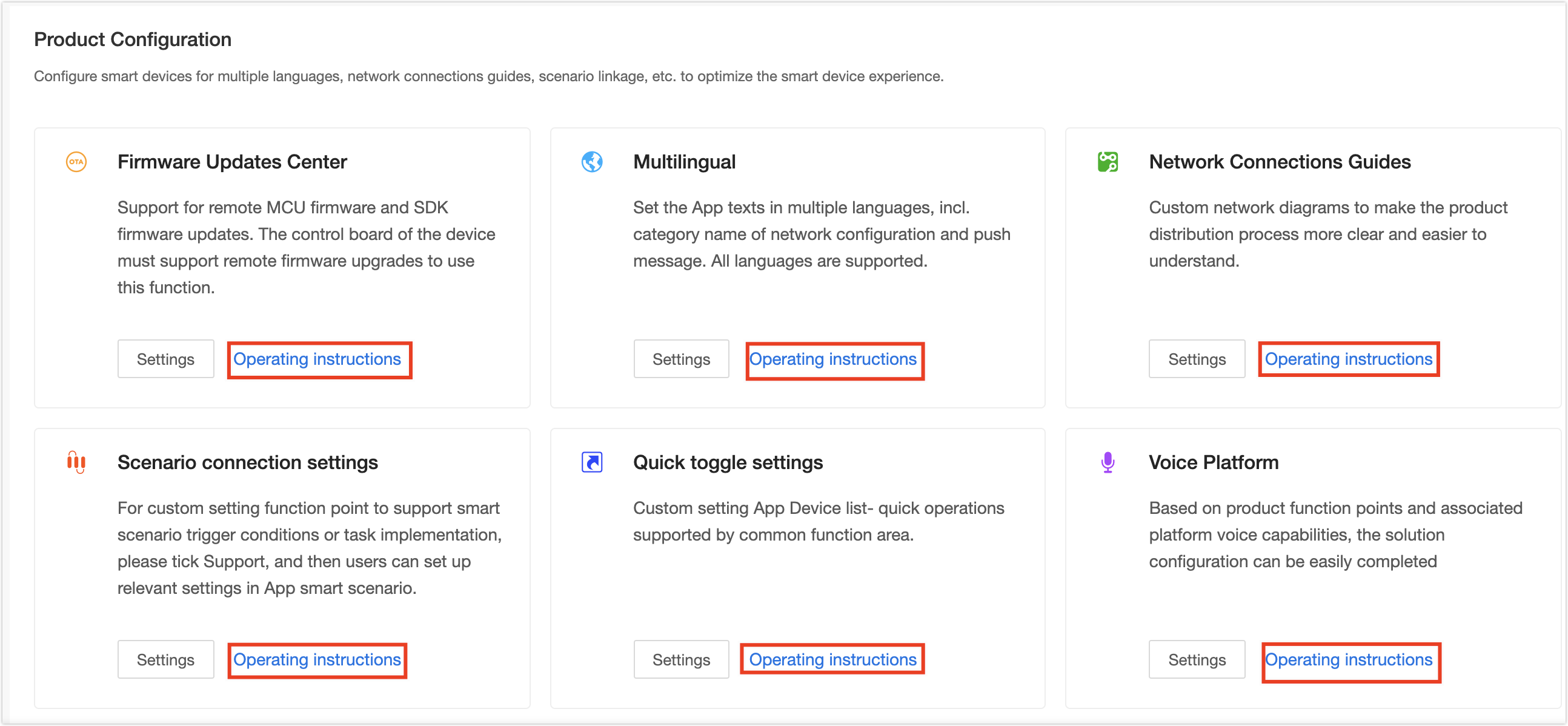
Test service
Follow the prompts on the page to perform a self-service test with the Tuya Cloud Test app and produce a test report. You can also subscribe to the Tuya Test service. When the test is completed, click Next: Product Release. 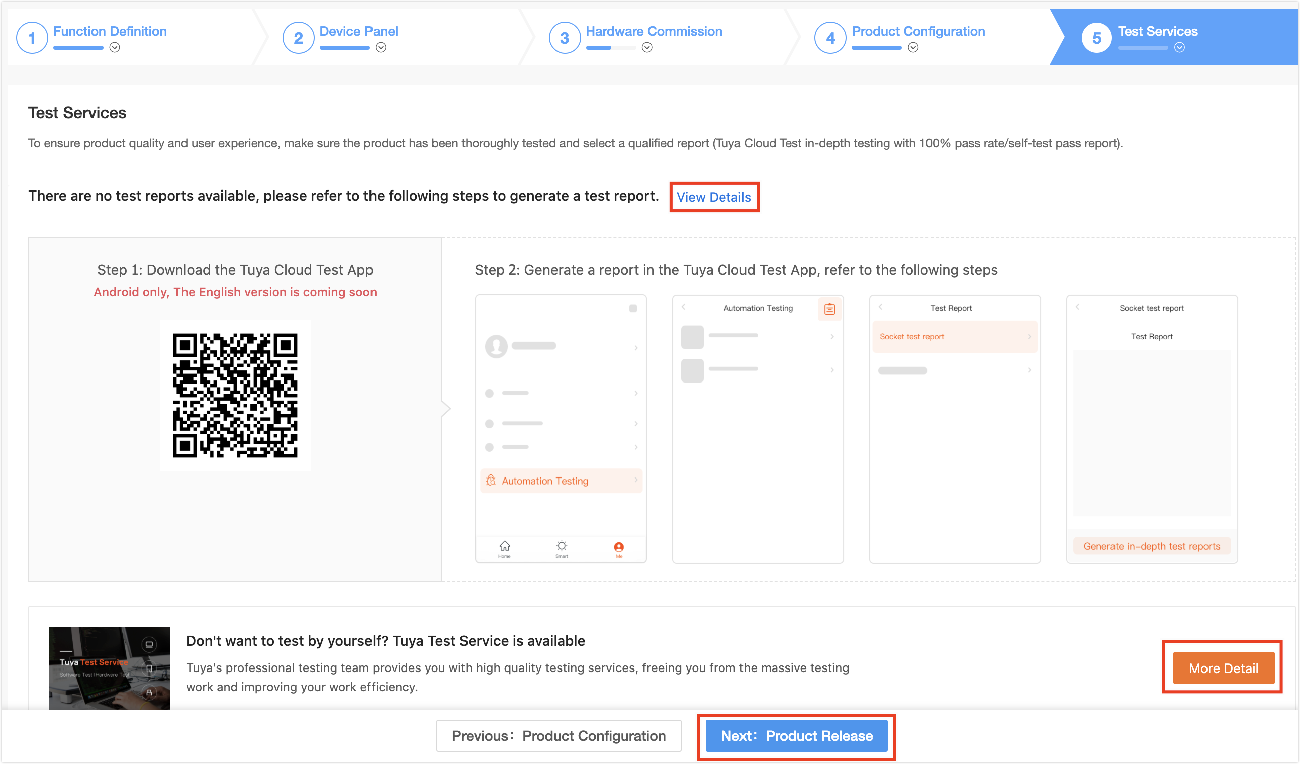
Note:
- Tuya Cloud Test app is only available for Android.
- For more information about the Tuya Cloud Test process, see Tuya Cloud Test App.
- Do not delete developing or completed products to avoid data loss and affecting proper product usage.
Is this page helpful?
YesFeedbackIs this page helpful?
YesFeedback


