Firmware Configuration
Last Updated on : 2024-06-21 04:08:29Copy for LLMView as MarkdownDownload PDF
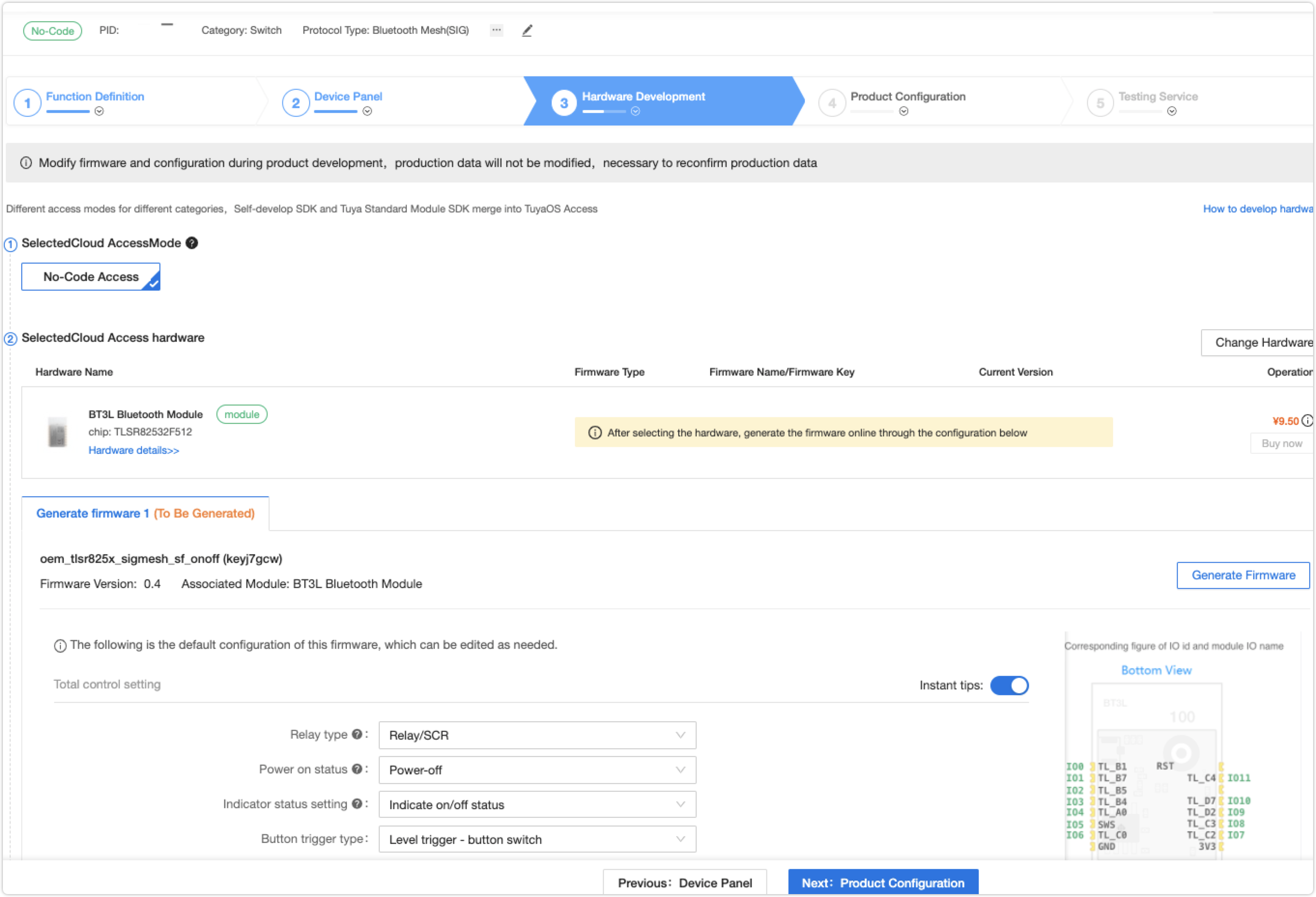
No-code development solution
Channel 1, 2, 3, 4
| Channel1, 2, 3, 4 | Configurable items | Remarks |
|---|---|---|
| ButtonIIO pin is configurable. High-level is active and low-level is active. | Cannot be empty | / |
| Relay | IO pin is configurable. | High-level is active and low-level is active. |
| Relay indicator | IO port is configurable, high-level is active and low-level is active. | The default is empty, the relay indicator is realized by hardware or multiplexed by network indicator. |
Master control settings
| Master control settings | Configurable item | Remarks |
|---|---|---|
| Status | ①Power off ②Power on ③Power-off memory |
Default status: power off |
| Type: Level trigger. Edge trigger. |
Level trigger: Triggering upon the button is pressed and released. Edge trigger-touch switch: Trigger immediately after the button is pressed. |
/ |
Net connection setting
| Master control settings | Configuration item | Remarks |
|---|---|---|
| Reset time/s | 3 to10 seconds can be set, with a 1 second step | Default value: 3 s |
| Trigger for the first-time pairing | ①Long press until the network light flashes: the device is in a low power consumption state when it is powered on, and needs to be manually reset to enter the distribution network mode (timeout 3min), without anti-error deletion function ②The network light flashes after power on: the device enters the distribution network immediately after power-on mode (no timeout exit function), no anti-error deletion function ③Equipment reconnection: The device is in a low power consumption state when powered on, and needs to be manually reset to enter the network distribution mode (timeout 3min), with anti-error deletion function ④Quick flashing after power-on Unconfigured network into low power consumption: the device enters the network distribution mode immediately after power-on (timeout 3min), without the function of preventing accidental deletion ⑤ Fast flashing when the power is turned on, the device reconnects with the device with low power consumption: the device enters the configuration immediately after power-on Net mode (timeout 3min), with anti-error deletion function |
Default value: long press until the network light flashes. |
| unlink_network_led_status | ①Off ②On ③Indicate relay status |
|
| Network indicator status when connected | ①Off ②On ③Indicate relay status |
|
| LED to indicate network status. | ①No reuse ②Reuse |
|
| Indicator light mixed color | ①Mixed color of indicator light. ②No mixed color of indicator light. |
|
| Network status indicator | I/O pin is configurable. High-level is active and low-level is active. |
Dual-control function setup
| Dual-control function setup | Configuration item | Remarks |
|---|---|---|
| Dual-control function selection | ①Does not support dual control function ②Level flip enable dual control-after selection, the corresponding on-off display "dual control trigger signal", operate the relay when there is a high and low-level flip change ③High and low level enable dual control-the corresponding channel after selection Display "dual control synchronous detection signal", used to synchronize the load status, do not operate the relay |
In addition to the hardware realization of the dual control function, it also supports app software dual control |
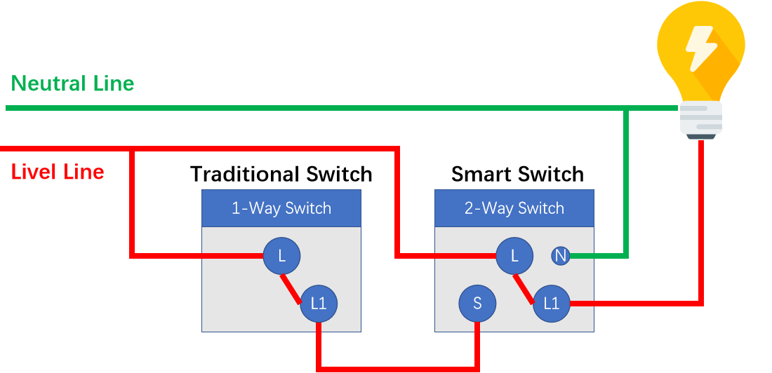 |
Level flip enable dual control: suitable for the combination of mechanical rocker switch + intelligent dual control switch |
|
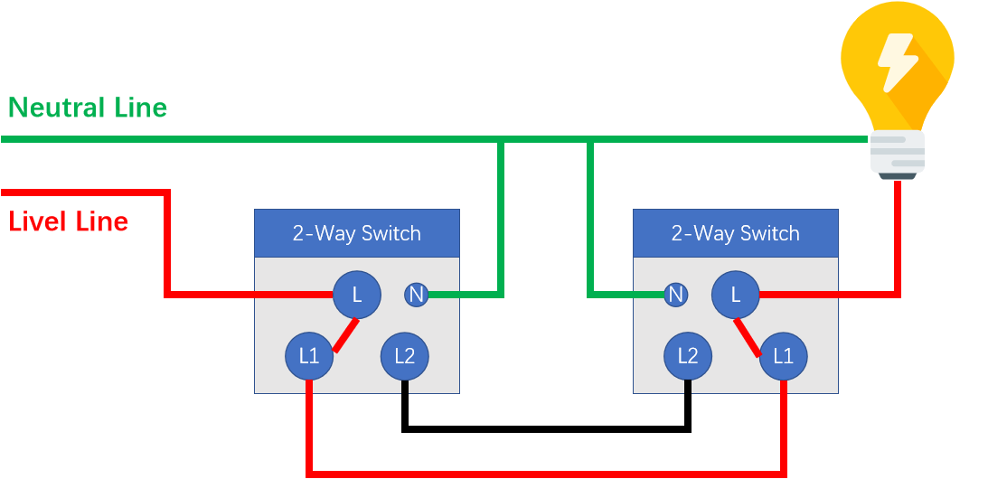 |
High and low level enable dual control: suitable for the combination of mechanical rocker switch + intelligent dual control switch or intelligent dual control switch + intelligent dual control switch. |
|
Switch configuration settings
| Switch configuration settings | Configuration item | Remarks |
|---|---|---|
| Backlight selection | ①Does not support the backlight function ②Supports the backlight function —After selection, the corresponding on-off display backlight indicator pin. IO is configurable, high and low levels are active. |
Is this page helpful?
YesFeedbackIs this page helpful?
YesFeedbackMarketing Cooperation
Business Cooperation
Customer Service
Media Inquiry


