Tuya Sandwich Wi-Fi SoC Board (E3S)
The Tuya Sandwich Wi-Fi SoC master control board (E3S) helps you quickly implement various smart hardware prototypes. You can use the Tuya Sandwich Wi-Fi SoC master control board (E3S) with other functional circuit modules or circuit boards to implement corresponding functions.
Scenarios
-
The Tuya Sandwich Wi-Fi SoC master control board (E3S) applies to many prototypes developed by Tuya IoT plug and play solutions, including sockets, power strips, and switches.
-
You also can implement diversified smart hardware demos with this development board.
-
The common scenarios of the Tuya Sandwich Wi-Fi SoC master control board (E3S) are as follows:
- Embedded systems engineers can use the board to perform preliminary embedded programming and debugging.
- App developers can use the board to develop and debug apps.
- Makers can use the board to quickly implement hardware demos and device control with the mobile phone.
- IoT technology enthusiasts can use the board to learn about the Wi-Fi control principle and smart device development.
Introduction to key components
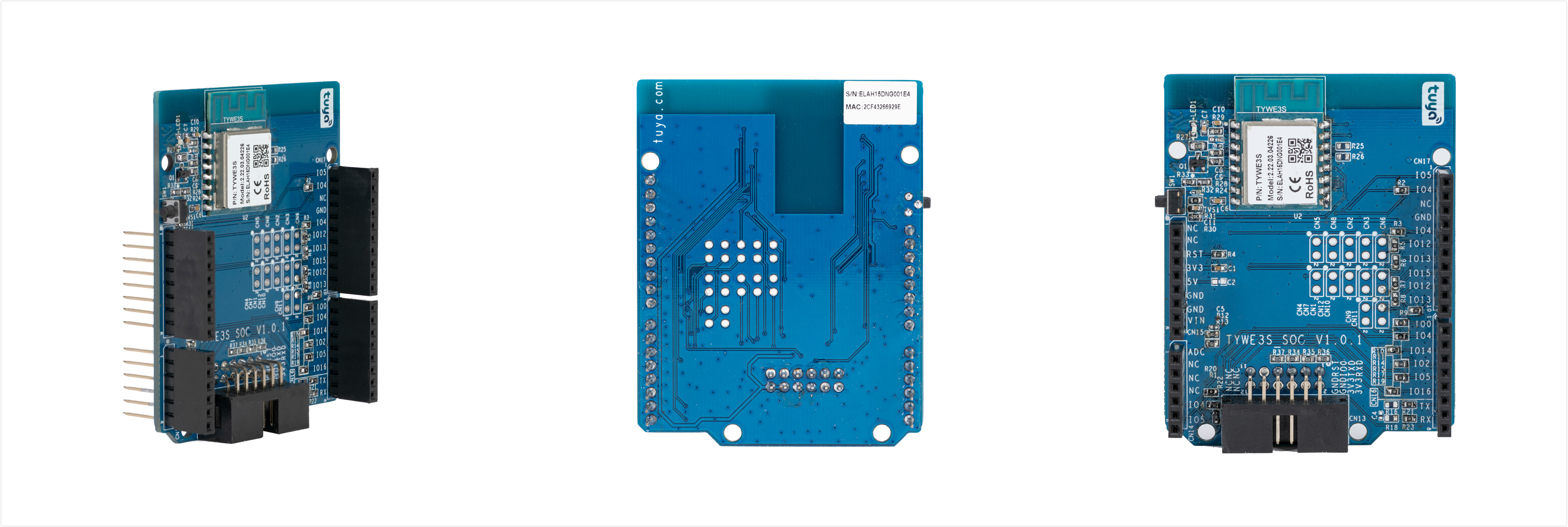
The Tuya Sandwich Wi-Fi SoC master control board (E3S) adopts the high-performance Wi-Fi module TYWE3S developed by Tuya Smart. The development board contains Wi-Fi module TYWE3S, buttons, LED indicators, user-defined I/O interfaces, power supply, and more. For more information, see TYWE3S Module Datasheet.
I/O ports and function definitions
- CN13 serial port for UART upgrade: Mainly used for system upgrade and debugging.
- LED indicator LED1: You can customize its functions. The indicator is controlled by I/O14 and is active high.
- Button SW1: You can customize its functions. The button is detected by I/O0. Its logic level is high when initialized and is low when pressed.
- Other GPIO ports: You can customize their functions. See the following table.
| No. | Symbol | Description |
|---|---|---|
| 1 | RST | I/O. The hardware reset pin, which is active low. |
| 2 | 3.3V | 3.3V power input pin. |
| 3 | 5V | NC. |
| 4 | GND | Power ground. |
| 5 | VIN | NC. |
| 6 | ADC | 10-bit SAR ADC. |
| 7 | IO4 | GPIO. It can be configured as PWM output or IIC_SDA. |
| 8 | IO5 | GPIO. It can be configured as PWM output or IIC_SCL. |
| 9 | IO3/RX | UART0, user serial port. |
| 10 | IO1/TX | UART0, user serial port. |
| 11 | IO16 | GPIO, pulled up. |
| 12 | IO2 | O, UART0_TXD, used to print the internal information of the module. |
| 13 | IO14 | GPIO. It can be configured as PWM output to serve as the indicator control pin and is pulled down. |
| 14 | IO0 | GPIO. It is pulled up and used in the process of module power-on initialization. Take caution to use it. |
| 15 | IO13 | GPIO. It can be configured as PWM output pin. |
| 16 | IO12 | GPIO. |
| 17 | IO15 | O. It is used in the process of module power-on initialization. Take caution to use it. |
Schematic diagram and PCB
-
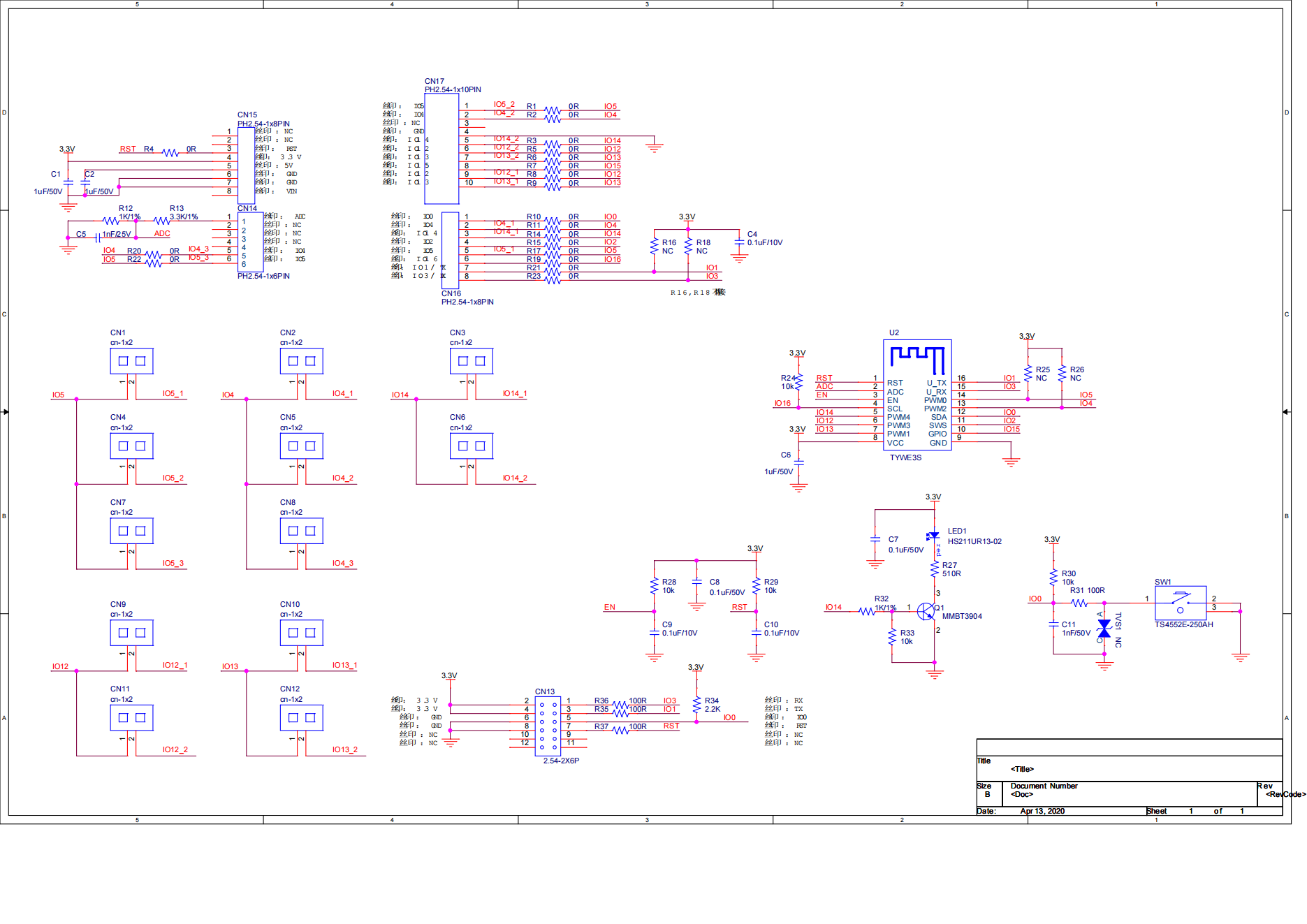
Schematic diagram of Tuya Sandwich Wi-Fi SoC master control board (E3S):
-
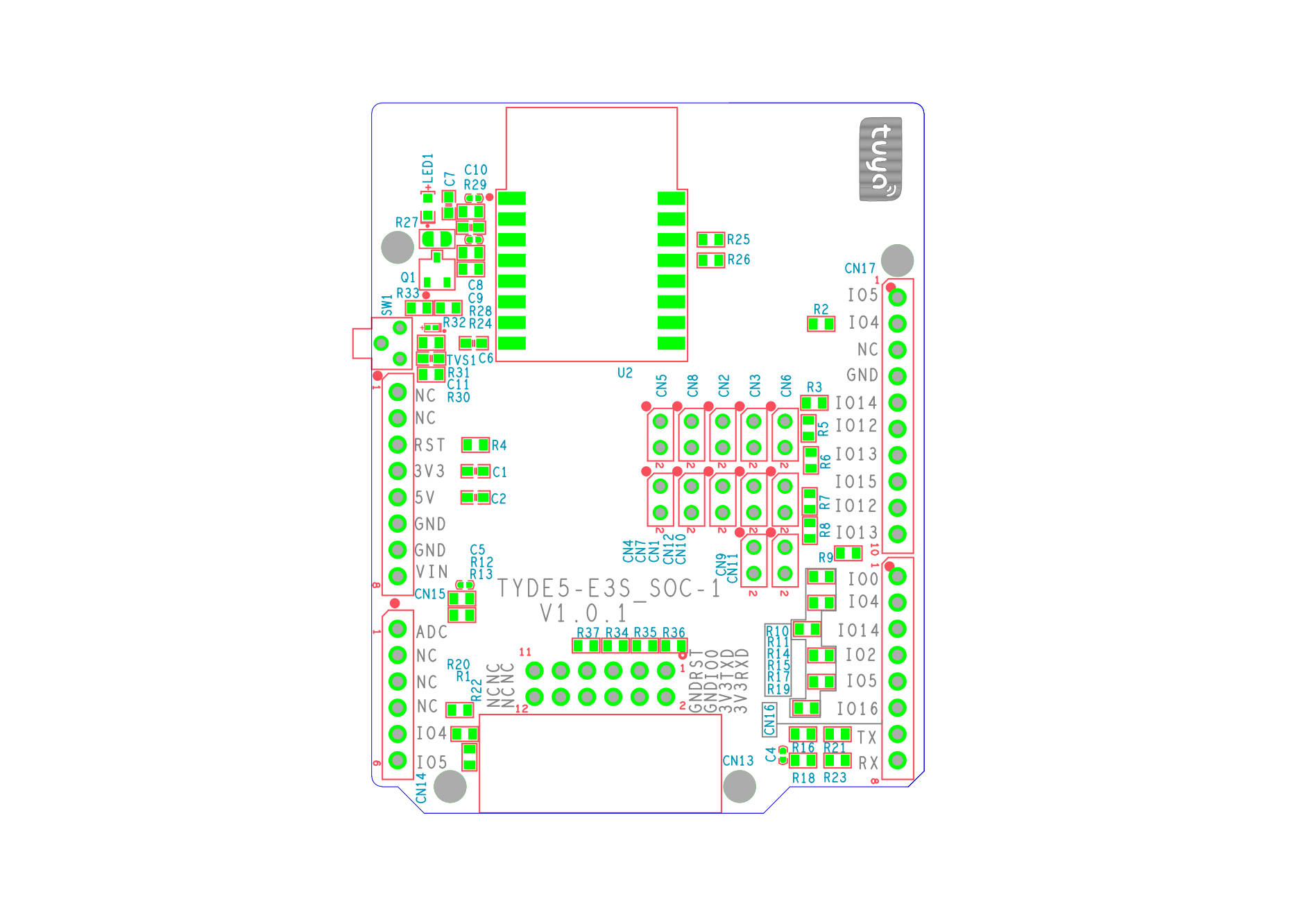
PCB of Tuya Sandwich Wi-Fi SoC master control board (E3S):
Things to note
- The development board in this solution must be used with a power board.
- The development board in this solution only supports 3.3V power input, and the supply current is not less than 350mA.
Is this page helpful?
YesFeedbackIs this page helpful?
YesFeedback


