Bluetooth Mesh Serial Protocol
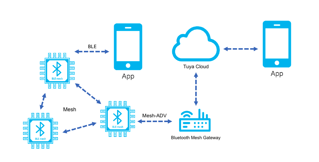
This topic describes the serial protocol that is used to implement serial communication between Tuya’s Bluetooth module and the third-party MCU. The following diagram shows how the two-way communication between the Bluetooth module and the cloud works.
Serial communication
| Parameter | Description |
|---|---|
| Baud (bit/s) | Auto-baud detection for 9600, 19200 and 115200. |
| Data bit | 8 |
| Parity | None |
| Stop bit | 1 |
| Data flow control | None |
Terms
| Term | Description |
|---|---|
| Data point (DP) | A DP refers to one function, one command, or a pair of commands. |
| Product ID (PID) | A unique ID assigned to each product created on the Tuya Developer Platform. The PID is associated with the product information, including DPs, app control panel, and purchase information. |
| Point-to-point mesh | Point-to-point communication means the channel is shared between two devices. |
| Point-to-multipoint mesh | Nodes are grouped in a network. When a node sends a message, only the members in this node group can receive it. |
| Bluetooth broadcast | When a device sends a message, all devices can receive it. |
| Node address | In the same Bluetooth mesh network, each node has a unique address. Its value ranges from 0x0001 to 0x5FFF. |
| Group address | Nodes in the same Bluetooth mesh network can belong to different groups, and each group has a unique address. Its value ranges from 0xC000 to 0xFEFF. |
| Broadcast address | In the same Bluetooth mesh network, all nodes can receive a broadcast. The Bluetooth mesh specification uses a model publish address as the destination address, which is 0xFFFF. |
Frame format
| Field | Length (byte) | Description |
|---|---|---|
| Header | 2 | It is fixed to 0x55aa. |
| Version | 1 | It is used for updates and extensions. |
| Command | 1 | Frame type |
| Data length | 2 | Big-endian |
| Data | N | Entity data |
| Checksum | 1 | Start from the header, add up all the bytes, and then divide the sum by 256 to get the remainder. |
All data greater than one byte is transmitted in big-endian format.
DP format
| Data segment | Length (byte) | Description | |||
| dpid | 1 | The identifier of a DP (DP ID). | |||
| type | 1 | It indicates the data type of a DP defined on the Tuya Developer Platform. | |||
| Type | Value | Length (byte) | Description | ||
| Raw | 0x00 | N | Represents a DP of raw data type. | ||
| Boolean | 0x01 | 1 | Represents a DP of boolean data type. Valid values include 0x00 and 0x01. | ||
| Value | 0x02 | 4 | Represents a DP of integer data type, represented in big-endian format. | ||
| String | 0x03 | N | Represents a DP of string data type. | ||
| Enum | 0x04 | 1 | Represents a DP of enum data type, ranging from 0 to 255. | ||
| Bitmap | 0x05 | 1/2/4 | Data greater than one byte is transmitted in big-endian format. | ||
| len | 2 | The length is the number of bytes of a value. | |||
| Value | 1/2/4/N | Represented in hexadecimal format. Data greater than one byte is transmitted in big-endian format. | |||
Bluetooth mesh is ideally suited for short data types, such as integer, boolean, enum, and bitmap. It is not intended for long data types, such as raw or string data of length greater than four bytes. The longer length will lead to more packets, longer transmission time, and lower success rate. If long data transmission is necessary, the len cannot exceed 40 bytes.
Serial protocol
Send heartbeats (0x00)
-
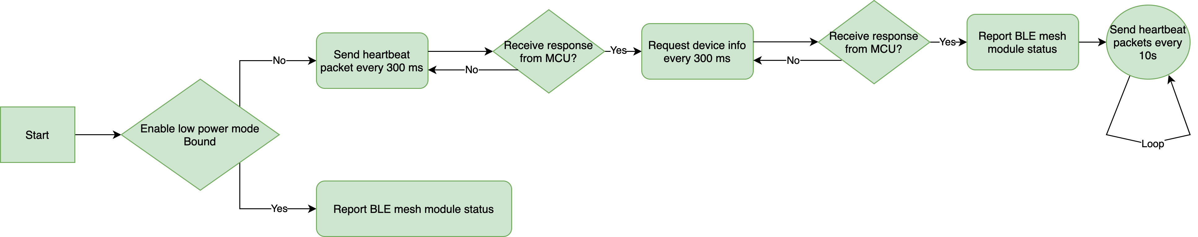
After power-on, the module will send a heartbeat to the MCU every 300 ms. If the MCU correctly responds to a heartbeat, it indicates proper operation. After the first-time heartbeat communication, the module will send the MCU a command to get product information.
-
The MCU can determine whether the module works properly by detecting heartbeats. If the module does not send heartbeats at regular intervals, the MCU can use the reset pin to reset the module.
-
After getting the product information, the module will send a heartbeat every 10 seconds in the standard power mode.
-
In the low power mode, the heartbeat communication will stop after a device joins a mesh network. After a restart, the Bluetooth module only sends the current network status to the MCU.
Since the heartbeat communication stops in the low power mode, the module cannot detect whether the MCU has been restarted.
The module sends the following command.
| No. | Length (byte) | Field | Description |
|---|---|---|---|
| 0 1 |
2 | Header | 0x55 0xAA |
| 2 | 1 | Version number | 0x00 |
| 3 | 1 | Command | 0x00 |
| 4 5 |
2 | Data length | 0x00 0x00 |
| 6 | 1 | CRC8 | Start from the header, add up all the bytes, and then divide the sum by 256 to get the remainder. |
The MCU returns the following command.
| No. | Length (byte) | Field | Description |
|---|---|---|---|
| 0 1 |
2 | Header | 0x55 0xAA |
| 2 | 1 | Version number | 0x00 |
| 3 | 1 | Command | 0x00 |
| 4 5 |
2 | Data length | 0x00 0x01 |
| 6 | 1 | Status | See the following table. |
| 7 | 1 | CRC8 | Start from the header, add up all the bytes, and then divide the sum by 256 to get the remainder. |
| Return value | Description |
|---|---|
| 0x00 | The MCU returns this value on the first-time heartbeat communication after a restart. The module uses this value to determine whether the MCU restarts during operation. |
| 0x01 | The MCU returns this value on recurring heartbeat communication. |
Get MCU information (0x01)
- Product key: 8-byte value assigned to each product for storing product information in the cloud.
- Product information: refers to the PID.
The module sends the following command.
| No. | Length (byte) | Field | Description |
|---|---|---|---|
| 0 1 |
2 | Header | 0x55 0xAA |
| 2 | 1 | Version number | 0x00 |
| 3 | 1 | Command | 0x01 |
| 4 5 |
2 | Data length | 0x00 0x00 |
| 6 | 1 | CRC8 | Start from the header, add up all the bytes, and then divide the sum by 256 to get the remainder. |
The MCU returns the following command.
| No. | Length (byte) | Field | Description |
|---|---|---|---|
| 0 1 |
2 | Header | 0x55 0xAA |
| 2 | 1 | Version number | 0x00 |
| 3 | 1 | Command | 0x01 |
| 4 5 |
2 | Data length | 0x00 0x0d |
| 6 to 18 | 0x0d | Data | See the following table. |
| 19 | 1 | CRC8 | Start from the header, add up all the bytes, and then divide the sum by 256 to get the remainder. |
-
Data format:
1 to 8 9 to 13 The PID. A reserved field populated with the MCU version number. The module does not parse this field. -
For example,
55 AA 00 01 00 0D 66 74 62 38 78 32 78 30 31 2E 30 2E 30 C0, indicating the PID isftb8x2x0and the MCU version number is1.0.0.
Send pairing state (0x03)
- The module sends this command to the MCU to notify its current pairing state. The valid values are
0x00(unpaired) and0x02(paired). - The module will send its current pairing state to the MCU after responding to the command
0x02. - The module will send its current pairing state to the MCU if the state changes.
The module sends the following command.
| No. | Length (byte) | Field | Description |
|---|---|---|---|
| 0 1 |
2 | Header | 0x55 0xAA |
| 2 | 1 | Version number | 0x00 |
| 3 | 1 | Command | 0x03 |
| 4 5 |
2 | Data length | 0x00 0x01 |
| 6 | 1 | Status | See the following table. |
| 7 | 1 | CRC8 | Start from the header, add up all the bytes, and then divide the sum by 256 to get the remainder. |
| Status | State | Note |
|---|---|---|
| 0x00 | Unpaired | The module is discoverable and unpaired. |
| 0x02 | Paired | The module has been paired with the mobile app. |
The following block diagram shows how the module communicates with the MCU.
Reset the module (0x04)
The MCU sends this command to disconnect a module from a mesh network. This way, the module will be reset and become unpaired.
The MCU sends the following command.
| No. | Length (byte) | Field | Description |
|---|---|---|---|
| 0 1 |
2 | Header | 0x55 0xAA |
| 2 | 1 | Version number | 0x00 |
| 3 | 1 | Command | 0x04 |
| 4 5 |
2 | Data length | 0x00 0x00 |
| 6 | 1 | CRC8 | Start from the header, add up all the bytes, and then divide the sum by 256 to get the remainder. |
For example, 55 aa 00 04 00 00 03
The module returns the following command.
| No. | Length (byte) | Field | Description |
|---|---|---|---|
| 0 1 |
2 | Header | 0x55 0xAA |
| 2 | 1 | Version number | 0x00 |
| 3 | 1 | Command | 0x04 |
| 4 5 |
2 | Data length | 0x00 0x00 |
| 6 | 1 | CRC8 | Start from the header, add up all the bytes, and then divide the sum by 256 to get the remainder. |
For example, 55 AA 00 04 00 00 03
Send commands (0x06)
- For more information about DPs, see the description of DP format.
- This command can only be used to send the data unit of a single DP to the MCU.
- This is an asynchronous command, corresponding to status reporting. For example, the module sends a command to turn off the light and the MCU sends
0x07to return the current on/off status after executing the control command.
The module sends the following command.
| No. | Length (byte) | Field | Description |
|---|---|---|---|
| 0 1 |
2 | Header | 0x55 0xAA |
| 2 | 1 | Version number | 0x00 |
| 3 | 1 | Command | 0x06 |
| 4 5 |
2 | Data length (Len) | High-order 8 bits Low-order 8 bits |
| 6 to 6+Len-1 | Len | DP | See the following table. |
| 6+Len | 1 | CRC8 | Start from the header, add up all the bytes, and then divide the sum by 256 to get the remainder. |
-
DP format (data of a single DP)
1 2 3 to 4 5 and followings dp1_id dp1_type dp1_len dp1_data -
For example, the MCU sends
55 aa 00 06 00 05 03 01 00 01 01 10, representing information described in the following table.Data Field Value 03 dp1_id 3 01 dp1_type Boolean 00 01 dp1_len 1 byte 01 dp1_data true
The MCU returns the following command.
None
Report status (0x07)
- For more information about DPs, see the description of DP format.
- The MCU can report the status of multiple DPs at the same time.
- This is an asynchronous command. The MCU uses it to report device status to the module, which can be triggered by three mechanisms.
- After the MCU executes the command received from the module, it reports the changed DP status to the module.
- When the MCU proactively detects status changes of DPs, it reports the changed DP status to the module.
- When the MCU receives the DP status query, it sends the status of all DPs to the module.
The MCU sends the following command.
| No. | Length (byte) | Field | Description |
|---|---|---|---|
| 0 1 |
2 | Header | 0x55 0xAA |
| 2 | 1 | Version number | 0x00 |
| 3 | 1 | Command | 0x07 |
| 4 5 |
2 | Data length (Len) | High-order 8 bits Low-order 8 bits |
| 6 to 6+Len-1 | Len | DP | See the following table. |
| 6+Len | 1 | CRC8 | Start from the header, add up all the bytes, and then divide the sum by 256 to get the remainder. |
-
DP format (data of a single or multiple DPs)
1 2 3 to 4 5 and followings … n n+1 n+2 to n+3 n+4 and followings dp_id dp_type dp_len dp_data … dpN_id dpN_type dpN_len dpN_data -
For example,
55 aa 00 07 00 05 03 01 00 01 01 11
The module returns the following command.
| No. | Length (byte) | Field | Description |
|---|---|---|---|
| 0 1 |
2 | Header | 0x55 0xAA |
| 2 | 1 | Version number | 0x00 |
| 3 | 1 | Command | 0x07 |
| 4 5 |
2 | Data length | 0x00 0x01 |
| 6 | 1 | Status | See the following table. |
| 7 | 1 | CRC8 | Start from the header, add up all the bytes, and then divide the sum by 256 to get the remainder. |
| Return value | Description |
|---|---|
| 0x00 | Succeeded |
| 0x01 | Failed |
Query status (0x08)
- This is an asynchronous command. The module uses it to query the current status of all DPs. The MCU will report the data the module queries through the command
0x07. - The module sends a status query when the following two events occur.
- For a paired module, it detects that the MCU is restarted based on the heartbeat communication.
- Users open the control panel of a device on the mobile app.
The module sends the following command.
| No. | Length (byte) | Field | Description |
|---|---|---|---|
| 0 1 |
2 | Header | 0x55 0xAA |
| 2 | 1 | Version number | 0x00 |
| 3 | 1 | Command | 0x08 |
| 4 5 |
2 | Data length | 0x00 0x00 |
| 6 | 1 | CRC8 | Start from the header, add up all the bytes, and then divide the sum by 256 to get the remainder. |
For example, 55 aa 00 08 00 00 07
The MCU returns the following command.
None
Report data proactively with ACK required (0x09)
- For more information about DPs, see the description of DP format.
- The MCU can report the status of multiple DPs at once.
- Blocking applies when the MCU proactively reports data with an ACK required. The module does not receive the next packet until responding to the current data reception. If the MCU reports data before receiving a response, a busy message will be returned.
- The MCU reports data twice by default. The module responds with the command
0x0B.
The MCU sends the following data.
| No. | Length (byte) | Field | Description |
|---|---|---|---|
| 0 1 |
2 | Header | 0x55 0xAA |
| 2 | 1 | Version number | 0x00 |
| 3 | 1 | Command (CMD) | 0x09 |
| 4 5 |
2 | Data length (Len) | Upper 8 bits Lower 8 bits |
| 6 | 1 | Mode | 0x00 |
| 7 | 1 | TID | The packet ID. The MCU increments the ID every time a packet is reported. |
| 8 to 8+Len-1 | Len | Data point | See the following table. |
| 8+Len | 1 | CRC8 | Start from the header, add up all the bytes, and then divide the sum by 256 to get the remainder. |
-
DP format (multiple DPs can be included):
1 2 3 4 and followings … n n+1 n+2 n+3 and followings dp_id dp_type dp_len dp_data … dpN_id dpN_type dpN_len dpN_data - When
dp_typeis Boolean (dp_datafixed to 1), value (dp_datafixed to 4), or enum (dp_datafixed to 1), the fielddp_lenis not required. - When
dp_typeis raw, string, or bitmap, you must specify the 1-byte fielddp_len.
- When
The module returns the following data.
| No. | Length (byte) | Field | Description |
|---|---|---|---|
| 0 1 |
2 | Header | 0x55 0xAA |
| 2 | 1 | Version number | 0x00 |
| 3 | 1 | Command (CMD) | 0x09 |
| 4 5 |
2 | Data length | 0x00 0x01 |
| 6 | 1 | Status | See the following table. |
| 7 | 1 | Timeout | Unit: Seconds |
| 8 | 1 | CRC8 | Start from the header, add up all the bytes, and then divide the sum by 256 to get the remainder. |
| Return value | Description |
|---|---|
| 0x00 | Success |
| 0x01 | Busy |
- The timeout is the maximum time that the MCU waits for a response from the module after sending a message. When the timeout is reached, the MCU considers data reporting as failed.
Configure module (0x0A)
This command configures the general features of a module.
The MCU sends the following data.
| No. | Length (byte) | Field | Description |
|---|---|---|---|
| 0 1 |
2 | Header | 0x55 0xAA |
| 2 | 1 | Version number | 0x00 |
| 3 | 1 | Command (CMD) | 0x0A |
| 4 5 |
2 | Data length | Upper 8 bits Lower 8 bits |
| 6 to 6 Len-1 |
Len | config_info | See the following table. |
| 6+Len | 1 | CRC8 | Start from the header, add up all the bytes, and then divide the sum by 256 to get the remainder. |
Example: 55 aa 00 0A 00 03 01 00 64 71
| config_kind | config_params | Description | Return |
|---|---|---|---|
| 0x01 | timeout() (in seconds) |
Specify how long an unpaired device can stay in pairing mode after power on.
|
Command 0x0A |
| 0x02 | 0x01: Turn on pairing. 0x00: Turn off pairing. |
Turn on or off pairing mode immediately. | Command 0x03. The module returns the result of the configuration. |
The module returns the following data.
| No. | Length (byte) | Field | Description |
|---|---|---|---|
| 0 1 |
2 | Header | 0x55 0xAA |
| 2 | 1 | Version number | 0x00 |
| 3 | 1 | Command (CMD) | 0x0A |
| 4 5 |
2 | Data length | 0x00 0x01 |
| 6 to 6 Len-1 |
Len | config_info_ack | See the following table. |
| 6 | 1 | CRC8 | Start from the header, add up all the bytes, and then divide the sum by 256 to get the remainder. |
| config_kind | config_params | Description |
|---|---|---|
| 0x01 | status (1 byte)
|
Return the result of pairing timeout settings. |
Respond to proactive data reporting (0x0B)
The module returns the result and details (TID) of data reporting. If the result is failure, the MCU can report data again.
The module sends the following data.
| No. | Length (byte) | Field | Description |
|---|---|---|---|
| 0 1 |
2 | Header | 0x55 0xAA |
| 2 | 1 | Version number | 0x00 |
| 3 | 1 | Command (CMD) | 0x0B |
| 4 5 |
2 | Data length (Len) | Upper 8 bits Lower 8 bits |
| 6 | 1 | TID | The packet ID. |
| 7 | 1 | Status | See the following table. |
| 8+Len | 1 | CRC8 | Start from the header, add up all the bytes, and then divide the sum by 256 to get the remainder. |
| Return value | Description |
|---|---|
| 0x00 | Success |
| 0x01 | Failure after retransmission |
The MCU returns the following data.
| No. | Length (byte) | Field | Description |
|---|---|---|---|
| 0 1 |
2 | Header | 0x55 0xAA |
| 2 | 1 | Version number | 0x00 |
| 3 | 1 | Command (CMD) | 0x0B |
| 4 5 |
2 | Data length | 0x00 0x01 |
| 6 | 1 | Status | See the following table. |
| 7 | 1 | CRC8 | Start from the header, add up all the bytes, and then divide the sum by 256 to get the remainder. |
| Return value | Description |
|---|---|
| 0x00 | Success |
| 0x01 | Failure |
Production test
Radio frequency (RF) (0x0E)
- Perform the received signal strength indicator (RSSI) test on modules to measure the RF performance.
- Test tool: a Bluetooth beacon that broadcasts an identifier named
ty_mdev. - Test steps: Put the beacon around 0.5 meters away from the module. The MCU sends this command to the module to initiate a test. The module will search for the designated identifier and return the RSSI. If the RSSI is greater than -70 dB, the RF performance is acceptable.
The module must be unpaired and operate in the standard power mode. If the module is paired and powered for 15 minutes, the module can never enter the test mode again.
The MCU sends the following command.
| No. | Length (byte) | Field | Description |
|---|---|---|---|
| 0 1 |
2 | Header | 0x55 0xAA |
| 2 | 1 | Version number | 0x00 |
| 3 | 1 | Command | 0x0E |
| 4 5 |
2 | Data length | 0x00 0x00 |
| 6 | 1 | CRC8 | Start from the header, add up all the bytes, and then divide the sum by 256 to get the remainder. |
The module returns the following command.
| No. | Length (byte) | Field | Description |
|---|---|---|---|
| 0 1 |
2 | Header | 0x55 0xAA |
| 2 | 1 | Version number | 0x00 |
| 3 | 1 | Command | 0x0E |
| 4 5 |
2 | Data length (Len) | High-order 8 bits Low-order 8 bits |
| 6 to 6+Len-1 | Len | Data | See the following table. |
| 6+Len | 1 | CRC8 | Start from the header, add up all the bytes, and then divide the sum by 256 to get the remainder. |
Data format
| Data | Description |
|---|---|
| {"ret":true,"rssi":"-55"} | The RSSI is -55 dB. |
| {"ret":false} | The designated signal is not found. |
Low power protocol
Enable low power mode (0xE5)
-
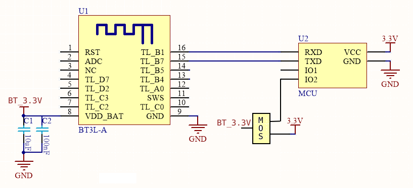
The MCU can power on or off the module with a triode to reduce power consumption. In the low power mode, unnecessary communication is reduced to speed up the initialization process and enable the module to quickly boot from the power-off state.
-
Circuit design
-
After the MCU wakes up the module to report DP status, the length of a DP determines how long the module is in the power-on state. You can use this formula to get the duration: (DP length + 3)/4 × 400 ms
The MCU sends the following command.
| No. | Length (byte) | Field | Description |
|---|---|---|---|
| 0 1 |
2 | Header | 0x55 0xAA |
| 2 | 1 | Version number | 0x00 |
| 3 | 1 | Command | 0xE5 |
| 4 5 |
2 | Data length | 0x00 0x01 |
| 6 | 1 | Data | See the following table. |
| 7 | 1 | CRC8 | Start from the header, add up all the bytes, and then divide the sum by 256 to get the remainder. |
Data format
| Data | Description |
|---|---|
| 0x00 | Disable low power mode. |
| 0x01 | Enable low power mode. |
The module returns the following command.
| No. | Length (byte) | Field | Description |
|---|---|---|---|
| 0 1 |
2 | Header | 0x55 0xAA |
| 2 | 1 | Version number | 0x00 |
| 3 | 1 | Command | 0xE5 |
| 4 5 |
2 | Data length | 0x00 0x01 |
| 6 | 1 | Status | See the following table. |
| 7 | 1 | CRC8 | Start from the header, add up all the bytes, and then divide the sum by 256 to get the remainder. |
| Return value | Description |
|---|---|
| 0x00 | Succeeded |
| Others | Failed |
Pre-control and beacon remote
Enable pre-control and beacon remote (0xA1)
- Pre-control and beacon remote are disabled by default. You can enable them through this command.
- With the beacon remote feature enabled, the module will stay in pairing mode for 60 seconds after being powered on.
- Up to five remotes can be paired. After the limit is reached, the system will automatically overwrite the oldest remote.
- The configuration is stored in the nonvolatile memory.
The MCU sends the following data.
| No. | Length (byte) | Field | Description |
|---|---|---|---|
| 0 1 |
2 | Header | 0x55 0xAA |
| 2 | 1 | Version number | 0x00 |
| 3 | 1 | Command (CMD) | 0xA1 |
| 4 5 |
2 | Data length | 0x00 0x01 |
| 6 | 1 | Data | See the following table. |
| 6 | 1 | CRC8 | Start from the header, add up all the bytes, and then divide the sum by 256 to get the remainder. |
Data format
| Data | Description |
|---|---|
| 0x00 | Disable pre-control and beacon remote. |
| 0x01 | Enable the beacon remote feature. |
| 0x02 | Enable the pre-control. |
| 0x03 | Enable pre-control and beacon remote. |
The module returns the following data.
| No. | Length (byte) | Field | Description |
|---|---|---|---|
| 0 1 |
2 | Header | 0x55 0xAA |
| 2 | 1 | Version number | 0x00 |
| 3 | 1 | Command (CMD) | 0xA1 |
| 4 5 |
2 | Data length | 0x00 0x01 |
| 6 | 1 | Status | See the following table. |
| 7 | 1 | CRC8 | Start from the header, add up all the bytes, and then divide the sum by 256 to get the remainder. |
| Return value | Description |
|---|---|
| 0x00 | Success |
| Others | Failure |
Beacon remote data notification (0xB0)
To use this command, the beacon remote feature must have been enabled.
The module sends the following data.
| No. | Length (byte) | Field | Description |
|---|---|---|---|
| 0 1 |
2 | Header | 0x55 0xAA |
| 2 | 1 | Version number | 0x00 |
| 3 | 1 | Command (CMD) | 0xB0 |
| 4 5 |
2 | Data length | Upper 8 bits Lower 8 bits |
| 6 | len | Data | See the following table. |
| 6+len | 1 | CRC8 | Start from the header, add up all the bytes, and then divide the sum by 256 to get the remainder. |
Data format
| Data | Length | Description |
|---|---|---|
| Data[0 to 5] | 6 | The MAC address of the remote. |
| Data[6] | 1 | Data length |
| Data[7] | 1 | DP ID (fixed as 0x0b) |
| Data[8] | 1 | DP type + DP length (fixed as 0x07) |
| Data[9] | 1 | ID |
| Data[10 to 15] | 6 | The commands for the beacon remote. |
The MCU returns the following data.
| No. | Length (byte) | Field | Description |
|---|---|---|---|
| 0 1 |
2 | Header | 0x55 0xAA |
| 2 | 1 | Version number | 0x00 |
| 3 | 1 | Command (CMD) | 0xB0 |
| 4 5 |
2 | Data length | 0x00 0x01 |
| 6 | 1 | Status | See the following table. |
| 7 | 1 | CRC8 | Start from the header, add up all the bytes, and then divide the sum by 256 to get the remainder. |
| Return value | Description |
|---|---|
| 0x00 | Success |
| Others | Failure |
Pre-control data notification (0xA2)
To use this command, the pre-control feature must have been enabled.
The module sends the following data.
| No. | Length (byte) | Field | Description |
|---|---|---|---|
| 0 1 |
2 | Header | 0x55 0xAA |
| 2 | 1 | Version number | 0x00 |
| 3 | 1 | Command (CMD) | 0xA2 |
| 4 5 |
2 | Data length | Upper 8 bits Lower 8 bits |
| 6 | len | Data | See the following table. |
| 6 | 1 | CRC8 | Start from the header, add up all the bytes, and then divide the sum by 256 to get the remainder. |
Data format
| Data | Length | Description |
|---|---|---|
| Data[0] | 1 | The pre-control command. |
| Data[1 to 12] | 12 | The pre-control parameter. |
The MCU returns the following data.
| No. | Length (byte) | Field | Description |
|---|---|---|---|
| 0 1 |
2 | Header | 0x55 0xAA |
| 2 | 1 | Version number | 0x00 |
| 3 | 1 | Command (CMD) | 0xB0 |
| 4 5 |
2 | Data length | 0x00 0x01 |
| 6 | 1 | Status | See the following table. |
| 7 | 1 | CRC8 | Start from the header, add up all the bytes, and then divide the sum by 256 to get the remainder. |
| Return value | Description |
|---|---|
| 0x00 | Success |
| Others | Failure |
Mesh-specific protocols
Enable communication between nodes (0xB1)
-
This feature is available on mobile app v3.20 and later.
-
After communication between nodes is enabled, the module will request eight publish addresses (
pub_address) from the cloud and save them to the storage. At the same time, quick pairing is disabled. In quick pairing mode, a device can be added to the mobile app within 3 to 5 seconds. With this mode disabled, the time will be about 10 seconds. -
The following figure shows how to enable local device linkage with eight publish addresses.
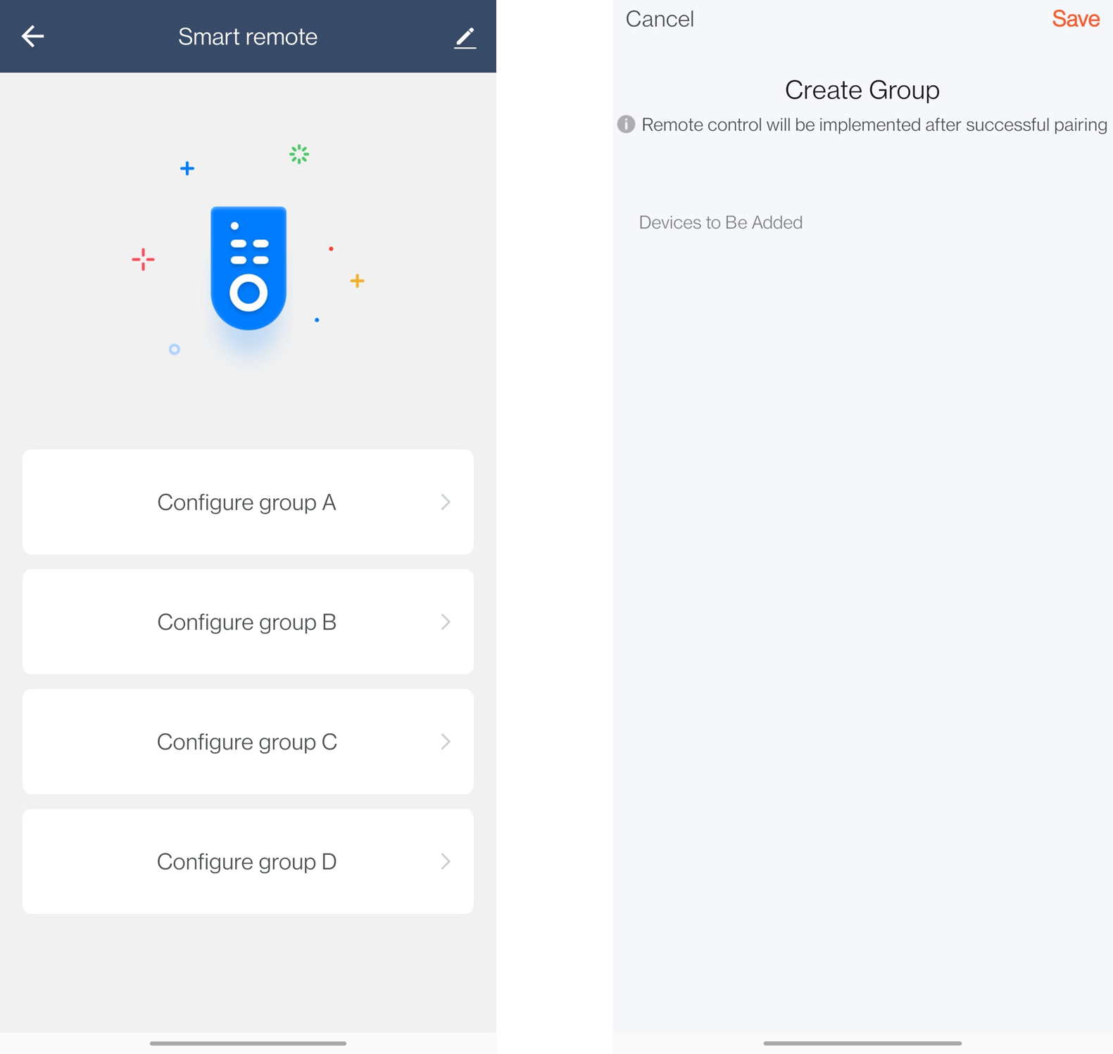
As shown above, open the control panel of the Bluetooth remote control. Tap Configure group A.
The destination address of group A is one of the eight publish addresses.
How to set up local linkage:
- The mobile app requests the publish address assigned to group A from the cloud.
- The mobile app requests the current device list of group A and the list of devices that can be added to this group.
- Users can add or remove a device. The mobile app will send a command to the physical device accordingly.
How to implement local linkage:
- Press the ON button on the remote control.
- The remote control will set the received publish address as the destination address and send the on/off control command to the target group.
- The smart lights in the target group will be turned on or off accordingly.
The MCU sends the following command.
| No. | Length (byte) | Field | Description |
|---|---|---|---|
| 0 1 |
2 | Header | 0x55 0xAA |
| 2 | 1 | Version number | 0x00 |
| 3 | 1 | Command | 0xB1 |
| 4 5 |
2 | Data length | 0x00 0x01 |
| 6 | 1 | Data | See the following table. |
| 7 | 1 | CRC8 | Start from the header, add up all the bytes, and then divide the sum by 256 to get the remainder. |
Data format
| Data | Description |
|---|---|
| 0x00 | Disable communication between nodes. |
| 0x01 | Enable communication between nodes. |
The module returns the following command.
| No. | Length (byte) | Field | Description |
|---|---|---|---|
| 0 1 |
2 | Header | 0x55 0xAA |
| 2 | 1 | Version number | 0x00 |
| 3 | 1 | Command | 0xB1 |
| 4 5 |
2 | Data length | 0x00 0x01 |
| 6 | 1 | Status | See the following table. |
| 7 | 1 | CRC8 | Start from the header, add up all the bytes, and then divide the sum by 256 to get the remainder. |
| Return value | Description |
|---|---|
| 0x00 | Succeeded |
| Others | Failed |
Nodes communicate with each other (0xB2)
-
The communication between nodes in a Bluetooth mesh network makes the local device linkage possible.
-
The precondition is that the sender has got the address of the receiver in advance, which can be implemented through the following methods.
- Method 1: When the sender is added to the mobile app, you can assign eight publish addresses to it and add devices to these eight groups as needed. For example, a remote control (the sender) features eight groups.
- Method 2: Broadcast control commands. Set the destination address to
0xFFFF. - Method 3: The sender reads and sets the address of the group it belongs to as the destination address. This way, devices in the same group can be linked. For example, in a parking lot, a row of PIR lights can be turned off when a light receives a command.
- Method 4: Send a DP command to the sender by using the mobile app. The destination address will be included in the command.
-
Things to note
- The Bluetooth mesh generic firmware v0.9 only supports method 2 and method 4.
- v1.0 supports method 3.
- v1.1 supports method 4 and adds support for serial communication with an MCU. It supports:
-
Request for the address assigned to the device when it is bound with the mobile app.
The eight publish addresses (
pub_address) are used to publish or send commands to a group.
-
The MCU sends the following command.
| No. | Length (byte) | Field | Description |
|---|---|---|---|
| 0 1 |
2 | Header | 0x55 0xAA |
| 2 | 1 | Version number | 0x00 |
| 3 | 1 | Command | 0xB2 |
| 4 5 |
2 | Data length | High-order 8 bits Low-order 8 bits |
| 6 | N | Data | See the following table. |
| 7 | 1 | CRC8 | Start from the header, add up all the bytes, and then divide the sum by 256 to get the remainder. |
Data format
| No. | Length | Field | Description |
|---|---|---|---|
| 0 1 |
2 | Destination address | Represented in big-endian format. The value can be the node address, group address, or broadcast address ( 0xFFFF). |
| 2 to N | N-1 | DP data | For more information about the DP format, see Report status (0x07). |
Get eight publish addresses (0xB3)
The MCU can request the eight publish addresses (pub_address) from the Bluetooth module.
The MCU sends the following command.
| No. | Length (byte) | Field | Description |
|---|---|---|---|
| 0 1 |
2 | Header | 0x55 0xAA |
| 2 | 1 | Version number | 0x00 |
| 3 | 1 | Command | 0xB3 |
| 4 5 |
2 | Data length | 0x00 0x00 |
| 6 | 1 | CRC8 | Start from the header, add up all the bytes, and then divide the sum by 256 to get the remainder. |
The module returns the following command.
| No. | Length (byte) | Field | Description |
|---|---|---|---|
| 0 1 |
2 | Header | 0x55 0xAA |
| 2 | 1 | Version number | 0x00 |
| 3 | 1 | Command | 0xB3 |
| 4 5 |
2 | Data length (Len) | High-order 8 bits Low-order 8 bits |
| 6 to 6+Len-1 | Len | Data | See the following table. |
| 6+Len | 1 | CRC8 | Start from the header, add up all the bytes, and then divide the sum by 256 to get the remainder. |
Data format
| No. | Length | Field | Description |
|---|---|---|---|
| 1 | 1 | adr_num | The number of publish addresses obtained. 0: no publish address returned. 8: eight publish addresses returned. If adr_num is 8, eight publish addresses of 16 bytes will be returned. |
| 2 to 17 | 16 | pub_address | Each address is two bytes, in the format of adr1, adr2, and so on. |
Query the group a device belongs to (0xB4)
The typical application of this command is group control in commercial lighting. For example, if a row of lights is added to one group when one of a light detects a coming vehicle, it will send a command to turn on the rest lights.
The MCU sends the following command.
| No. | Length (byte) | Field | Description |
|---|---|---|---|
| 0 1 |
2 | Header | 0x55 0xAA |
| 2 | 1 | Version number | 0x00 |
| 3 | 1 | Command | 0xB4 |
| 4 5 |
2 | Data length | 0x00 0x00 |
| 6 | 1 | CRC8 | Start from the header, add up all the bytes, and then divide the sum by 256 to get the remainder. |
The module returns the following command.
| No. | Length (byte) | Field | Description |
|---|---|---|---|
| 0 1 |
2 | Header | 0x55 0xAA |
| 2 | 1 | Version number | 0x00 |
| 3 | 1 | Command | 0xB4 |
| 4 5 |
2 | Data length (Len) | High-order 8 bits Low-order 8 bits |
| 6 to 6+Len-1 | Len | Data | See the following table. |
| 6+Len | 1 | CRC8 | Start from the header, add up all the bytes, and then divide the sum by 256 to get the remainder. |
Data format
| No. | Length | Field | Description |
|---|---|---|---|
| 1 | 1 | adr_num | The number of publish addresses obtained. 0: The device does not belong to any group. 8: The device might belong to one of the groups. If adr_num is 8, eight publish addresses of 16 bytes will be returned.Note that if |
| 2 to 17 | 16 | pub_address | Each address is two bytes, in the format of adr1, adr2, and so on. |
Sync the remote with a device through hardware operations (0xB5)
The user can sync the remote control with a device in two ways:
- Sync the remote control with a device by using the mobile app. For more information, see the command
0xB1. - Sync the remote control with a device through hardware operations, without using the mobile app.
You can sync the remote control with devices through hardware operations without using the mobile app, as shown in the following steps.
- Use the command
0xB6to make a device enter sync mode through an external event trigger such as a button press or power-on. - Use the command
0xB5to make the remote control start syncing with the device through an external event trigger such as a button press. - The LED indicator of the device that the remote control successfully syncs with will blink.
- This way, the remote control can send messages to the publish address through the command
0xB2. (To enable a device to be synced with and controlled by a remote control, see the command0xB6.)
The MCU sends the following command.
| No. | Length (byte) | Field | Description |
|---|---|---|---|
| 0 1 |
2 | Header | 0x55 0xAA |
| 2 | 1 | Version number | 0x00 |
| 3 | 1 | Command | 0xB5 |
| 4 5 |
2 | Data length | High-order 8 bits Low-order 8 bits |
| 6 | Len | Data | See the following table. |
| 7 | 1 | CRC8 | Start from the header, add up all the bytes, and then divide the sum by 256 to get the remainder. |
Data format
| Field | Value | Description |
|---|---|---|
| data[0] | 0x00 0x01 |
unpair pair |
| data[1] | address type | 0x00: the offset publish address. Specify an offset in data[2]. This command will make a device subscribe to the pub_address[offset]. 0x01: the real destination address. Specify the real address in big endian in data[2–3], this command will make a device subscribe to the address passed in. |
The module returns the following command.
| No. | Length (byte) | Field | Description |
|---|---|---|---|
| 0 1 |
2 | Header | 0x55 0xAA |
| 2 | 1 | Version number | 0x00 |
| 3 | 1 | Command | 0xB5 |
| 4 5 |
2 | Data length | 0x00 0x01 |
| 6 | 1 | Status | See the following table. |
| 7 | 1 | CRC8 | Start from the header, add up all the bytes, and then divide the sum by 256 to get the remainder. |
| Return value | Description |
|---|---|
| 0x00 | Succeeded |
| Others | Failed |
Enable time window (0xB6)
The command 0xB5 enables a device to act as a remote control to sync with and control other devices. The command 0xB6 enables a device to be synced with and controlled by a remote control. This can meet the needs of a device that can function as both a remote control and a regular controlled device.
However, the time window for the sync process is not always on. The command 0xB6 is used to turn on the time window. The duration setup is also supported. This way, remote controls can sync with devices only in the specified time window. For example:
- Light bulbs: A time window is turned on for 10 seconds after the light bulb is powered on.
- Power strip: A time window is turned on for 10 seconds after a button is pressed and held.
The MCU sends the following command.
| No. | Length (byte) | Field | Description |
|---|---|---|---|
| 0 1 |
2 | Header | 0x55 0xAA |
| 2 | 1 | Version number | 0x00 |
| 3 | 1 | Command | 0xB6 |
| 4 5 |
2 | Data length | 0x00 0x01 |
| 6 | 1 | Data | The duration of a time window, in seconds. |
| 7 | 1 | CRC8 | Start from the header, add up all the bytes, and then divide the sum by 256 to get the remainder. |
The module returns the following command.
| No. | Length (byte) | Field | Description |
|---|---|---|---|
| 0 1 |
2 | Header | 0x55 0xAA |
| 2 | 1 | Version number | 0x00 |
| 3 | 1 | Command | 0xB6 |
| 4 5 |
2 | Data length | 0x00 0x01 |
| 6 | 1 | Status | See the following table. |
| 7 | 1 | CRC8 | Start from the header, add up all the bytes, and then divide the sum by 256 to get the remainder. |
| Return value | Description |
|---|---|
| 0x00 | Succeeded |
| 0x01 | Failed |
| 0x02 | Times out. |
| 0x03 | Device is synced. |
Add to favorites (0xB7)
This command applies to devices that support the favorites feature. It allows users to add the setup of a device to favorites so that they can quickly restore the device to this saved setup. Up to four setups can be added.
For example, users can adjust a group of devices to the desired setting and add the current setup to the favorite so that they can apply one of the saved setups to the device with one tap.
The MCU sends the following command.
| No. | Length (byte) | Field | Description |
|---|---|---|---|
| 0 1 |
2 | Header | 0x55 0xAA |
| 2 | 1 | Version number | 0x00 |
| 3 | 1 | Command | 0xB7 |
| 4 5 |
2 | Data length | High-order 8 bits Low-order 8 bits |
| 6 | Len | Data | See the following table. |
| 7 | 1 | CRC8 | Start from the header, add up all the bytes, and then divide the sum by 256 to get the remainder. |
Data format
| Field | Value | Description |
|---|---|---|
| data[0] | 0x01 0x02 |
Add a setup to favorites. Execute a setup in the favorites. |
| data[1] | The ID of a favorite (0x00–0x03) | Up to four setups can be added to favorites and the IDs are 0, 1, 2, and 3. |
| data[2] | address type | 0x00: the offset publish address. Specify an offset in data[3]. This command will make a device subscribe to the pub_address[offset]. 0x01: the real destination address. Specify the real address in big endian in data[3–4]. |
The module returns the following command.
| No. | Length (byte) | Field | Description |
|---|---|---|---|
| 0 1 |
2 | Header | 0x55 0xAA |
| 2 | 1 | Version number | 0x00 |
| 3 | 1 | Command | 0xB7 |
| 4 5 |
2 | Data length | 0x00 0x01 |
| 6 | 1 | Status | See the following table. |
| 7 | 1 | CRC8 | Start from the header, add up all the bytes, and then divide the sum by 256 to get the remainder. |
| Return value | Description |
|---|---|
| 0x00 | Succeeded |
| Others | Failed |
Notification of adding favorites (0xB8)
The module sends the following command.
| No. | Length (byte) | Field | Description |
|---|---|---|---|
| 0 1 |
2 | Header | 0x55 0xAA |
| 2 | 1 | Version number | 0x00 |
| 3 | 1 | Command | 0xB8 |
| 4 5 |
2 | Data length | 0x00 0x02 |
| 6 | 2 | Data | See the following table. |
| 7 | 1 | CRC8 | Start from the header, add up all the bytes, and then divide the sum by 256 to get the remainder. |
Data format
| Field | Value | Description |
|---|---|---|
| data[0] | 0x01 0x02 |
Add a setup to favorites. Execute a setup in the favorites. |
| data[1] | id (0x00 to 0x03) | Up to four setups can be added to favorites and the IDs are 0, 1, 2, and 3. |
The MCU returns the following command.
| No. | Length (byte) | Field | Description |
|---|---|---|---|
| 0 1 |
2 | Header | 0x55 0xAA |
| 2 | 1 | Version number | 0x00 |
| 3 | 1 | Command | 0xB8 |
| 4 5 |
2 | Data length | 0x00 0x01 |
| 6 | 1 | Status | See the following table. |
| 7 | 1 | CRC8 | Start from the header, add up all the bytes, and then divide the sum by 256 to get the remainder. |
| Return value | Description |
|---|---|
| 0x00 | Succeeded |
| Others | Failed |
Send messages defined by standard mesh models (0xBC)
0xBC, 0xBD, 0xBE, and 0xBF are advanced commands. Before applying them to your product, it is important to have a good understanding of the Bluetooth mesh models and Tuya’s data models.
This command is used to send messages defined by standard mesh models to a publish address. For example, a Bluetooth remote control can send messages to switch on or dim lights.
The standard models adopted in the Tuya protocol.
| Model | Applicable |
|---|---|
| Generic OnOff Model | On/off control of lights and electrical products |
| Light Lightness Model | The brightness of lights |
| Light CTL Temperature Model | The color temperature of lights |
| Light HSL Model | Colored lights. The color data received by the module is in HSL, which will be converted to HSV to send to the MCU. |
The MCU sends the following command.
| No. | Length (byte) | Field | Description |
|---|---|---|---|
| 0 1 |
2 | Header | 0x55 0xAA |
| 2 | 1 | Version number | 0x00 |
| 3 | 1 | Command | 0xBC |
| 4 5 |
2 | Data length | High-order 8 bits Low-order 8 bits |
| 6 | Len | Data | See the following table. |
| 7 | 1 | CRC8 | Start from the header, add up all the bytes, and then divide the sum by 256 to get the remainder. |
Data format
| Field | Value | Description |
|---|---|---|
| data[0–1] | dst_address of two bytes, represented in big-endian format |
Destination address |
| data[2–3] | opcode of two bytes, represented in big-endian format |
For more information about the opcode, visit the official Bluetooth website. |
| data[4] | is_rsp (0 = no; 1 = is rsp) | Specify whether an acknowledgement is required. |
| data[5] | cmd_params_len | Parameter length |
| data[6–n] | cmd_params | Parameter |
The module returns the following command.
| No. | Length (byte) | Field | Description |
|---|---|---|---|
| 0 1 |
2 | Header | 0x55 0xAA |
| 2 | 1 | Version number | 0x00 |
| 3 | 1 | Command | 0xBC |
| 4 5 |
2 | Data length | 0x00 0x01 |
| 6 | 1 | Status | See the following table. |
| 7 | 1 | CRC8 | Start from the header, add up all the bytes, and then divide the sum by 256 to get the remainder. |
| Return value | Description |
|---|---|
| 0x00 | Succeeded |
| Others | Failed |
Receive messages defined by standard mesh models (0xBD)
0xBC, 0xBD, 0xBE, and 0xBF are advanced commands. Before applying them to your product, it is important to have a good understanding of the Bluetooth mesh models and Tuya’s data models.
This command is used to receive messages defined by standard mesh models. For example, Bluetooth lights can receive messages from a remote control.
The module sends the following command.
| No. | Length (byte) | Field | Description |
|---|---|---|---|
| 0 1 |
2 | Header | 0x55 0xAA |
| 2 | 1 | Version number | 0x00 |
| 3 | 1 | Command | 0xBD |
| 4 5 |
2 | Data length | High-order 8 bits Low-order 8 bits |
| 6 | Len | Data | See the following table. |
| 7 | 1 | CRC8 | Start from the header, add up all the bytes, and then divide the sum by 256 to get the remainder. |
Data format
| Field | Value | Description |
|---|---|---|
| data[0–1] | src_address of two bytes, represented in big-endian format |
Source address |
| data[2–3] | dst_address of two bytes, represented in big-endian format |
Destination address |
| data[4–5] | opcode of two bytes, represented in big-endian format |
For more information about the opcode, visit the official Bluetooth website. |
| data[6] | is_ack (0 = no; 1 = need ack) | Specify whether an acknowledgement is required. |
| data[7] | cmd_params_len | Parameter length |
| data[8–n] | cmd_params | Parameter |
The MCU returns the following command.
| No. | Length (byte) | Field | Description |
|---|---|---|---|
| 0 1 |
2 | Header | 0x55 0xAA |
| 2 | 1 | Version number | 0x00 |
| 3 | 1 | Command | 0xBD |
| 4 5 |
2 | Data length | 0x00 0x01 |
| 6 | 1 | Status | See the following table. |
| 7 | 1 | CRC8 | Start from the header, add up all the bytes, and then divide the sum by 256 to get the remainder. |
| Return value | Description |
|---|---|
| 0x00 | Succeeded |
| Others | Failed |
Send messages defined by vendor-specific mesh models (0xBE)
0xBC, 0xBD, 0xBE, and 0xBF are advanced commands. Before applying them to your product, it is important to have a good understanding of the Bluetooth mesh models and Tuya’s data models.
This command is used to send messages defined by vendor-specific mesh models to a publish address. For example, a Bluetooth remote control can send messages to Bluetooth lights to switch between lighting scenes.
The MCU sends the following command.
| No. | Length (byte) | Field | Description |
|---|---|---|---|
| 0 1 |
2 | Header | 0x55 0xAA |
| 2 | 1 | Version number | 0x00 |
| 3 | 1 | Command | 0xBE |
| 4 5 |
2 | Data length | High-order 8 bits Low-order 8 bits |
| 6 | Len | Data | See the following table. |
| 7 | 1 | CRC8 | Start from the header, add up all the bytes, and then divide the sum by 256 to get the remainder. |
Data format
| Field | Value | Description |
|---|---|---|
| data[0–1] | dst_address of two bytes, represented in big-endian format |
Destination address |
| data[2] | is_rsp (0 = no; 1 = is rsp) | Specify whether an acknowledgement is required. |
| data[3] | cmd_params_len | Parameter length |
| data[4–n] | cmd_params | Parameter |
The module returns the following command.
| No. | Length (byte) | Field | Description |
|---|---|---|---|
| 0 1 |
2 | Header | 0x55 0xAA |
| 2 | 1 | Version number | 0x00 |
| 3 | 1 | Command | 0xBE |
| 4 5 |
2 | Data length | 0x00 0x01 |
| 6 | 1 | Status | See the following table. |
| 7 | 1 | CRC8 | Start from the header, add up all the bytes, and then divide the sum by 256 to get the remainder. |
| Return value | Description |
|---|---|
| 0x00 | Succeeded |
| Others | Failed |
Receive messages defined by vendor-specific mesh models (0xBF)
0xBC, 0xBD, 0xBE, and 0xBF are advanced commands. Before applying them to your product, it is important to have a good understanding of the Bluetooth mesh models and Tuya’s data models.
This command is used to receive messages defined by vendor-specific mesh models. For example, Bluetooth lights can receive messages from a remote control.
The module sends the following command.
| No. | Length (byte) | Field | Description |
|---|---|---|---|
| 0 1 |
2 | Header | 0x55 0xAA |
| 2 | 1 | Version number | 0x00 |
| 3 | 1 | Command | 0xBF |
| 4 5 |
2 | Data length | High-order 8 bits Low-order 8 bits |
| 6 | Len | Data | See the following table. |
| 7 | 1 | CRC8 | Start from the header, add up all the bytes, and then divide the sum by 256 to get the remainder. |
Data format
| Field | Value | Description |
|---|---|---|
| data[0–1] | src_address of two bytes, represented in big-endian format |
Source address |
| data[2–3] | dst_address of two bytes, represented in big-endian format |
Destination address |
| data[4] | is_ack (0 = no; 1 = need ack) | Specify whether an acknowledgement is required. |
| data[5] | cmd_params_len | Parameter length |
| data[6–n] | cmd_params | Parameter |
The MCU returns the following command.
| No. | Length (byte) | Field | Description |
|---|---|---|---|
| 0 1 |
2 | Header | 0x55 0xAA |
| 2 | 1 | Version number | 0x00 |
| 3 | 1 | Command | 0xBF |
| 4 5 |
2 | Data length | 0x00 0x01 |
| 6 | 1 | Status | See the following table. |
| 7 | 1 | CRC8 | Start from the header, add up all the bytes, and then divide the sum by 256 to get the remainder. |
| Return value | Description |
|---|---|
| 0x00 | Succeeded |
| Others | Failed |
Additional features
Get the time (0xD1)
This command is supported by firmware v3.0 or later. When the power is off, the Bluetooth module of the node loses its time, which will be restored after sync with the server. The node automatically requests the current time after a data exchange with the mobile phone or gateway. Or, it proactively sends a time request to other devices (those with time data) on the mesh network after being powered on.
The MCU sends the following data.
| No. | Length (byte) | Field | Description |
|---|---|---|---|
| 0 1 |
2 | Header | 0x55 0xAA |
| 2 | 1 | Version number | 0x00 |
| 3 | 1 | Command (CMD) | 0xD1 |
| 4 5 |
2 | Data length | 0x00 0x01 |
| 6 | 1 | Time data flag | The lowest five bits represent the flags for Unix time, time zone, longitude and latitude, sunrise and sunset, and day of week and 24-hour time. For example, 0x0001 1111 specifies that Unix time, time zone, longitude and latitude, sunrise and sunset, and day of week and 24-hour time should be returned in the response. |
| 7 | 1 | CRC8 | Start from the header, add up all the bytes, and then divide the sum by 256 to get the remainder. |
The module returns the following data.
| No. | Length (byte) | Field | Description |
|---|---|---|---|
| 0 1 |
2 | Header | 0x55 0xAA |
| 2 | 1 | Version number | 0x00 |
| 3 | 1 | Command (CMD) | 0xD1 |
| 4 5 |
2 | Data length | n |
| 6 | n | Time data | See the following table. |
| 7 | 1 | CRC8 | Start from the header, add up all the bytes, and then divide the sum by 256 to get the remainder. |
Field description
| Field | Length | Description |
|---|---|---|
| Flag | 1 byte | The flag in the request. For example, 0b0001 1111 has its five lowest bits set to 1, specifying that Unix time, time zone, longitude and latitude, sunrise and sunset, and day of week and 24-hour time should be returned in the response. |
| Unix time | 4 bytes | If the flag of the Unix time is 1, byte 2 to byte 5 in the response represent the Unix time. If the value of this field is 0xFFFFFFFF, it indicates the device has not obtained the time data. |
| Time zone | 2 bytes | The time zone. Its value is a signed integer and 100 times the actual time zone. For example, 800 represents GMT+8. |
| Longitude and latitude | 4 bytes | The longitude, with a maximum value of 180.00. For example, 23° 27′ 30″ E equals 23.45833° E in decimal degrees. Its value is a signed integer and 100 times the actual longitude. For example, 23° 27′ E is 2345, and 23° 30′ W is -2350. The longitude is converted in the same manner. For example, 23° 27′ N is 2345, and 23° 30′ S is -2350. |
| Sunrise and sunset | 4 bytes | The sunrise time (2 bytes), represented in 24-hour clock format. 00:00 indicates zero o’clock. The sunset time (2 bytes), represented in 24-hour clock format. 00:00 indicates zero o’clock. |
| Day of week + 24-hour time | 3 bytes | The day of the week (1 byte). 0: Sunday. 1 to 6: Monday to Saturday. The time of day in 24-hour clock format (2 bytes). 00:00 indicates zero o’clock. |
The set of the flag field determines the existence of the subsequent fields. For example, when the flag is 0b00001001, the flag, time zone, and 24-hour time are included in the response.
Change history
| Version | Changes | Date | Description |
|---|---|---|---|
| 2.4.0 | Added | March 22, 2024 | Added the command for module configuration. |
| 2.3.0 | Added | December 26, 2023 | Added the command for proactive data reporting response. |
| 2.2.0 | Added | November 29, 2023 | 1. Added pre-control and beacon remote. 2. Added the command for getting the time. |
| 2.1.0 | Added | September 27, 2021 | 1. Added the pass-through transmission in the Bluetooth mesh model and vendor model. |
| 2.0.0 | Added | May 1, 2021 | 1. Added features of syncing the remote with a device through hardware operations and adding setups to favorites. |
| 1.1.0 | Modified | June 2, 2020 | 1. Added 9600 and 115200 to auto-baud detection. 2. Added querying the group a device belongs to. |
| 0.9.0 | Modified | May 2020 | 1. Fixed the issue of wrongly erased authorization information in a production test. 2. Supported requesting publish addresses. |
| 0.8.0 | Modified | March 5, 2020 | 1. Deleted the responding process to commands from the module. 2. Added quick pairing. |
| 0.7.0 | Modified | March 1, 2020 | 1. Added the node-to-node communication. 2. Added RSSI test on network modules. 3. Added RSSI test on end products. |
| 0.6.0 | Modified | August 4, 2019 | Added production test on PCB. |
| 0.3.0 | Modified | July 9, 2019 | Modified the valid values of the pairing state. |
| 0.2.0 | Modified | July 2019 | Added responses to get or set messages. |
| 0.1.0 | Created | June 5, 2019 | The first release |
Is this page helpful?
YesFeedbackIs this page helpful?
YesFeedback


