TYBT4 Module
This topic describes the embedded Bluetooth module TYBT4 developed by Tuya Smart.
Scope of application
TYBT4 is an embedded Bluetooth module developed by Tuya Smart. The module consists of a highly integrated Bluetooth chip TLSR8266 and a few peripheral components, with a built-in Bluetooth network protocol stack and various library functions. TYBT4 also contains a low power 32-bit MCU, Bluetooth Low Energy (LE)/2.4G radio, 512 KB flash, 16 KB static random access memory (SRAM), and 9 reusable I/O ports. For more information, see TYBT4 Module Datasheet.
Typical application diagram
-
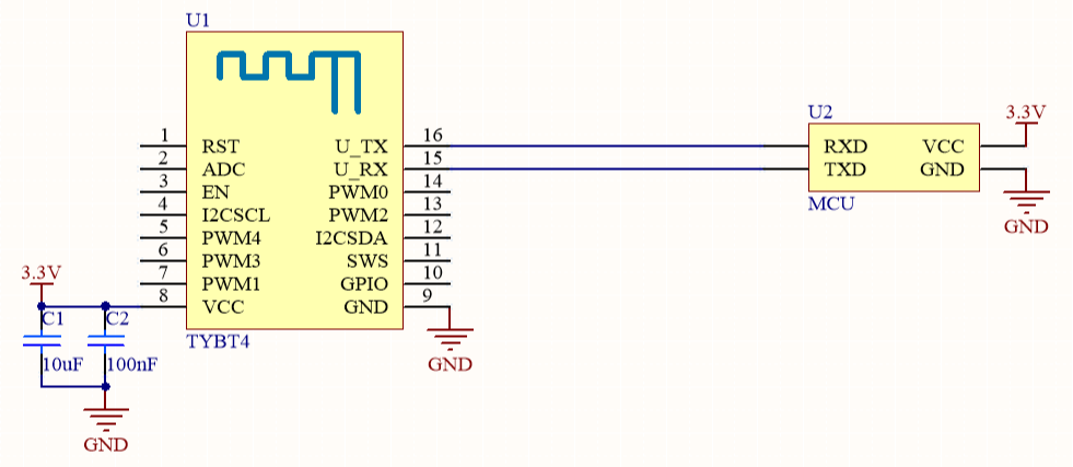
Figure 1 is a reference diagram of the coordinated processing mode of the module and 3.3 V MCU.
-
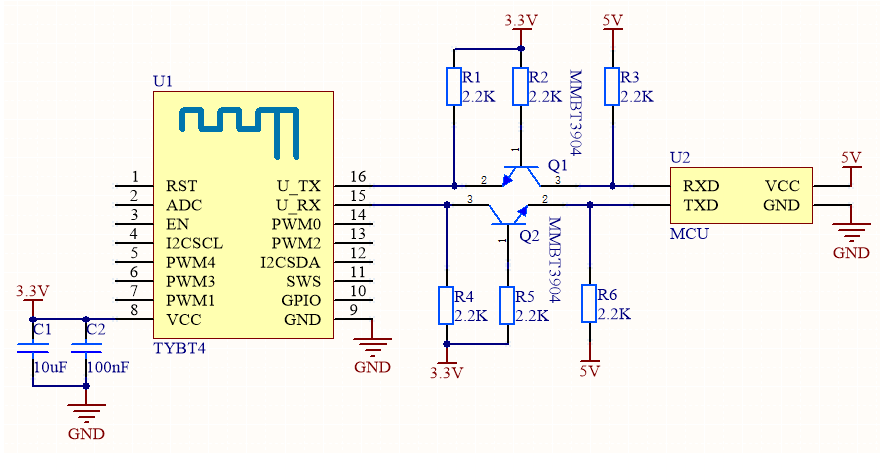
Figure 2 is a reference diagram of the coordinated processing mode of the module and 5 V MCU.
Design specification
- Module power supply:
- It is recommended that the supply current of the 3.3 V module should exceed 100 mA, and the total capacity of the external filter capacitor should exceed 10 uF.
- In the PCB layout, the filter capacitor at the power input pin shall be arranged near the power supply pin.
- Module pin:
- A power on reset (POR) circuit is added inside the RST pin. Also, the module can be controlled by the general-purpose input/output (GPIO) port of the MCU. Pay attention to electrical level conversion.
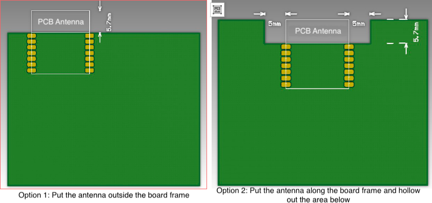
- Radio frequency (RF) of the module: It is recommended that the distance between the module antenna and other metal parts should be at least 15 mm, in order to optimize the RF performance. Through the surface mount technology (SMT) process, TYBT4 is attached to the main control board to work with other components. The module position and placement, and its distance from the shell directly affect the RF performance. The following are positions that are recommended and not recommended.
-
The antenna of the TYBT4 module is placed outside the board frame. It is recommended to use the placement positions of Option 1 and Option 2. The antenna is outside the board frame, or the board near the antenna must be hollowed out. The performance is basically the same as the RF test performance of a single module.
-
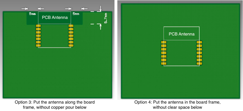
If the PCB antenna must be placed on the bottom plate due to design restrictions, you can refer to the placement of Option 3. The antenna is inside the board frame, but there is no copper pour and wiring near the antenna. However, it will cost some RF performance, almost with an attenuation of 1–2 dB.
-
It is not recommended to use the placement position of Option 4. The antenna is inside the board frame, and there is copper pour or wiring below the antenna. The RF signal will be significantly attenuated.
-
Is this page helpful?
YesFeedbackIs this page helpful?
YesFeedback


