Serial Communication Protocol
This topic describes the serial protocol that is used to interface your MCU with Tuya’s NB-IoT module.
Serial communication
- Baud: 9600/115200
- Data bit: 8
- Parity check: none
- Stop bit: 1
- Data flow control: none
- MCU: microcontroller unit. Your MCU communicates with Tuya’s modules through the serial port. The serial protocol is designed to enable full-duplex communication between the device and the server.
Frame format
-
All data greater than one byte is transmitted in big-endian format.
-
All sample data in the protocol is in hexadecimal format.
-
The module sends packets and waits for a response. If no response is received within one second, the unanswered packets will be retransmitted three times.
-
One command is sent by one party and received by the other party synchronously. That is, one party sends a command and waits for a response from the other party. If the sender does not receive a correct response packet within a specified time period, the transmission times out.
For more information, see Protocol list.
-
The MCU reports status synchronously. Assume that the MCU reports a command
N. The data transmission is as follows.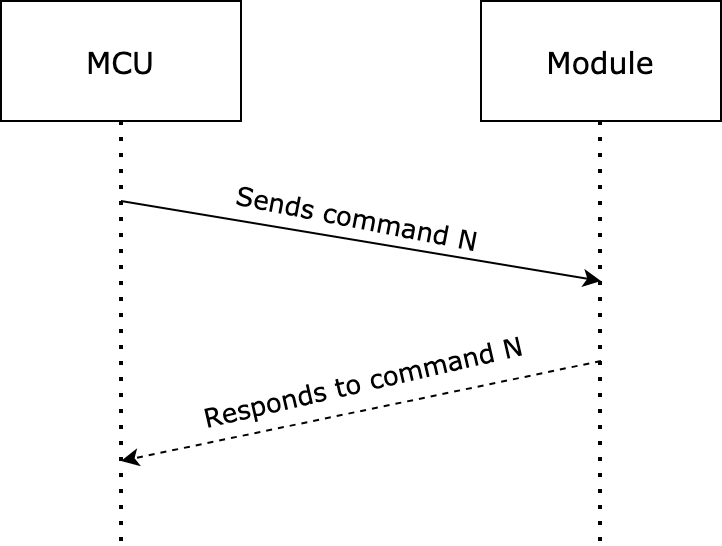
Field Bytes Description Header 2 It is fixed to 0x55aa.Version 1 It is used for updates and extensions. Command 1 Frame type. Data length 2 Big-endian format. Data N The data from the network layer is included, such as the IP address packet. Checksum 1 Start from the header, add up all the bytes, and then divide the sum by 256 to get the remainder.
Basic protocol
Query product information
Product information consists of parameters such as product ID and MCU software version number.
- Product ID (PID): a unique identifier assigned to each product created on the Tuya Developer Platform for storing product information in the cloud.
- MCU software version number: expressed in dot-decimal notation. For example,
x.x.x(0 ≤ x ≤ 99), andxis a decimal digit.
The module sends the following data.
| Field | Bytes | Description |
|---|---|---|
| Header | 2 | 0x55aa |
| Version | 1 | 0x00 |
| Command | 1 | 0x01 |
| Data length | 2 | 0x0000 |
| Data | 0 | None |
| Checksum | 1 | Start from the header, add up all the bytes, and then divide the sum by 256 to get the remainder. |
Example:
55 aa 00 01 00 00 00
The MCU returns the following data.
| Field | Bytes | Description |
|---|---|---|
| Header | 2 | 0x55aa |
| Version | 1 | 0x00 |
| Command | 1 | 0x01 |
| Data length | 2 | N |
| Data | N | {"p":"gl9iswyeobu5s93j", "v":"1.0.0", "s":"psm", "c":"isp"} {"p":"gl9iswyeobu5s93j", "v":"1.0.0", "s":"psm", "c":"isp","t":"22092217004703"} |
| Checksum | 1 | Start from the header, add up all the bytes, and then divide the sum by 256 to get the remainder. |
Data
| Parameters | Required | Description |
|---|---|---|
| p | Yes | The PID of the product you create on the Tuya Developer Platform. |
| v | Yes | The MCU version number. |
| s | Yes | The power consumption mode.
|
| c | Yes | Cloud connectivity.
|
| t | No | For time-sensitive scenarios, you can instruct the MCU to configure the RTC of the NB-IoT module. For example, create a local schedule in the format 22092217004703.
|
Example:
55 AA 00 01 00 38 7B 22 70 22 3A 22 67 6C 39 69 73 77 79 65 6F 62 75 35 73 39 33 6A 22 2C 22 76 22 3A 22 31 2E 30 2E 30 22 2C 22 73 22 3A 22 70 73 6D 22 2C 22 63 22 3A 22 69 73 70 22 7D 02
Report network status
| Network status | Description | Status value |
|---|---|---|
| Status 1 | The module is searching for a carrier to register to. | 0x01 |
| Status 2 | The module is connecting to the carrier’s network. | 0x02 |
| Status 3 | The module is registered to the carrier but not bound with the Tuya IoT cloud. | 0x03 |
| Status 4 | The module is bound with and connected to the Tuya IoT cloud. | 0x04 |
| Status 5 | The module attempting to attach to the network is rejected. | 0x05 |
The module sends the following data.
| Field | Bytes | Description |
|---|---|---|
| Header | 2 | 0x55aa |
| Version | 1 | 0x00 |
| Command | 1 | 0x02 |
| Data length | 2 | 0x0001 |
| Data | 1 | The network connection status.
|
| Checksum | 1 | Start from the header, add up all the bytes, and then divide the sum by 256 to get the remainder. |
Example:
The module is bound with and connected to the Tuya IoT cloud.
55 aa 00 02 00 01 04 06
The MCU returns the following data.
| Field | Bytes | Description |
|---|---|---|
| Header | 2 | 0x55aa |
| Version | 1 | 0x00 |
| Command | 1 | 0x02 |
| Data length | 2 | 0x0000 |
| Data | 0 | None |
| Checksum | 1 | Start from the header, add up all the bytes, and then divide the sum by 256 to get the remainder. |
Example:
55 aa 00 02 00 00 01
Reset the module
The module is reset to factory defaults and unbound from the Tuya IoT cloud.
The MCU sends the following data.
| Field | Bytes | Description |
|---|---|---|
| Header | 2 | 0x55aa |
| Version | 1 | 0x00 |
| Command | 1 | 0x03 |
| Data length | 2 | 0x0000 |
| Data | 0 | None |
| Checksum | 1 | Start from the header, add up all the bytes, and then divide the sum by 256 to get the remainder. |
Example:
55 aa 00 03 00 00 02
The module returns the following data.
| Field | Bytes | Description |
|---|---|---|
| Header | 2 | 0x55aa |
| Version | 1 | 0x00 |
| Command | 1 | 0x03 |
| Data length | 2 | 0x0000 |
| Data | 0 | None |
| Checksum | 1 | Start from the header, add up all the bytes, and then divide the sum by 256 to get the remainder. |
Example:
55 aa 00 03 00 00 02
Report real-time status
This command can be executed successfully only when the module is connected to the Tuya IoT cloud.
The MCU reports the real-time status of DPs to the module.
- This is a synchronous command. The MCU reports DP status and then waits for the result from the module. Ideally, the cloud returns the result within five seconds.
- The MCU can report the status of single or multiple DPs at a time, depending on your needs.
Scenarios
With this command, devices such as smart alarms can send the real-time status of a DP to the cloud for delivering instant alerts to the users.
The MCU sends the following data.
| Field | Bytes | Description |
|---|---|---|
| Header | 2 | 0x55aa |
| Version | 1 | 0x00 |
| Command | 1 | 0x05 |
| Data length | 2 | It depends on the protocol version as well as the type and number of data units. |
| Message ID | 2 | It applies to protocol versions 0x01 and later. Protocol version 0x00 does not include this field. |
| Data | N | Single or multiple data units. |
| Checksum | 1 | Start from the header, add up all the bytes, and then divide the sum by 256 to get the remainder. |
The module returns the following data.
| Field | Bytes | Description |
|---|---|---|
| Header | 2 | 0x55aa |
| Version | 1 | 0x00 |
| Command | 1 | 0x05 |
| Data length | 2 | The value of this field is 0x0001 for protocol version 0x00, and 0x0003 for versions 0x01 and later. |
| Message ID | 2 | It applies to protocol versions 0x01 and later. Protocol version 0x00 does not include this field. |
| Data | 1 | 0x00: success. 0x01: failure. |
| Checksum | 1 | Start from the header, add up all the bytes, and then divide the sum by 256 to get the remainder. |
-
Report a single data unit (protocol version
0x00)Example:
The DP 109 is of Boolean data type, and its value is
1. The MCU sends the following data.55 aa 00 05 00 05 6d 01 00 01 01 79 -
Report multiple data units (protocol version
0x00)Example:
- Status data 1: The DP 109 is of Boolean data type, and its value is
1. - Status data 2: The DP 102 is of string data type, and its value is
201804121507that is transferred in ASCII mode.
The MCU sends the following data.
55 aa 00 05 00 15 6d 01 00 01 01 66 03 00 0c 32 30 31 38 30 34 31 32 31 35 30 37 5d - Status data 1: The DP 109 is of Boolean data type, and its value is
-
Report a single data unit (protocol versions
0x01and later)-
Message ID:
0x00FF -
Status data: The DP 109 is of Boolean data type, and its value is
1. The MCU sends the following data.55 AA 01 05 00 07 00 FF 6D 01 00 01 01 7B
-
-
Report multiple data units (protocol versions
0x01and later)-
Message ID:
0x0100 -
Status data 1: The DP 109 is of Boolean data type, and its value is
1. -
Status data 2: The DP 102 is of string data type, and its value is 201804121507 that is transferred in ASCII mode. The MCU sends the following data.
55 AA 01 05 00 17 01 00 6D 01 00 01 01 66 03 00 0C 32 30 31 38 30 34 31 32 31 35 30 37 61
-
Report record-type data
A piece of record-type data contains the status of multiple DPs, which should be reported in one packet. If the device is offline when the MCU reports data, the module will retain this data and send it to the cloud on the next reporting operation.
- Stranded data: Each time the module successfully reports a piece of stranded data to the cloud, it sends
0x01to the MCU through the command0x08. - Cloud connection: If the network works fine, the module will be connected to the cloud within 30 seconds after the first power on. The MCU needs to wait for the network status from the module before reporting record-type data. However, if the MCU does not receive the status of a successful cloud connection within six seconds, it can report data through this command
0x08and then wait for the result. - Data length: The maximum payload size for each packet is 100 bytes. When the module is offline, it will return a failure if the MCU reports the data whose length exceeds the limit.
- Maximum records: The module can retain up to 20 historical records. When the limit is reached, the newest record will overwrite the oldest one.
- Return result: The module returns the result of a reporting operation to the MCU.
0x00: Reporting succeeded.- The reported data is sent to the cloud and no data is stranded.
- The module is offline and retains the reported data to its flash memory.
0x01: The reported data is sent to the cloud but stranded data exists.0x02: Reporting failed.
- Timestamp: Carrying a timestamp ensures that the reported data reflects the actual events when the module is offline. If you use the time when the data arrives at the server, the time of the stranded data is not the one when the event actually occurs. Therefore, when a module is paired for the first time, if the network works fine, the MCU should sync with the server time through the serial protocol. This way, the carried system time will prevail when the server processes the stranded data.
Scenarios
For the door lock, its MCU can report record-type data with a system timestamp. In case of transient network failure, the module can retain the received data and send it to the cloud on the next reporting operation.
The MCU sends the following data.
| Field | Bytes | Description |
|---|---|---|
| Header | 2 | 0x55aa |
| Version | 1 | 0x00 |
| Command | 1 | 0x08 |
| Data length | 2 | It depends on the protocol version as well as the type and number of data units. |
| Message ID | 2 | It applies to protocol versions 0x01 and later. Protocol version 0x00 does not include this field. |
| Data | 7 | If you use the MCU’s system timestamp, take the following format.
|
| N | Single or multiple data units. | |
| Checksum | 1 | Start from the header, add up all the bytes, and then divide the sum by 256 to get the remainder. |
Example:
-
Report a single data unit (protocol version
0x00)The DP 109 is of Boolean data type, and its value is
1. The RTC time of the module prevails. The MCU sends the following data.55 aa 00 08 00 0c 00 00 00 00 00 00 00 6d 01 00 01 01 d1 -
Report multiple data units (protocol version
0x00)-
Status data 1: The DP 109 is of Boolean data type, and its value is 1.
-
Status data 2: The DP 102 is of string data type, and its value is
201804121507that is transferred in ASCII mode. The server time prevails. The MCU sends the following data.55 aa 00 08 00 1c 00 00 00 00 00 00 00 6d 01 00 01 01 66 03 00 0c 32 30 31 38 30 34 31 32 31 35 30 37 a7
-
-
Report a single data unit (protocol versions
0x01and later)-
Message ID:
0x00FF -
The DP 109 is of Boolean data type, and its value is
1. The RTC time of the module prevails. The MCU sends the following data.55 AA 01 08 00 0E 00 FF 00 00 00 00 00 00 00 6D 01 00 01 01 85
-
-
Report multiple data units (protocol versions
0x01and later)-
Message ID:
0x0100 -
Status data 1: The DP 109 is of Boolean data type, and its value is
1. -
Status data 2: The DP 102 is of string data type, and its value is 201804121507 that is transferred in ASCII mode. The server time prevails. The MCU sends the following data.
55 AA 01 08 00 1E 01 00 00 00 00 00 00 00 00 6D 01 00 01 01 66 03 00 0C 32 30 31 38 30 34 31 32 31 35 30 37 6B
-
The module returns the following data.
| Field | Bytes | Description |
|---|---|---|
| Header | 2 | 0x55aa |
| Version | 1 | 0x00 |
| Command | 1 | 0x08 |
| Data length | 2 | The value of this field is 0x0001 for protocol version 0x00, and 0x0003 for versions 0x01 and later. |
| Message ID | 2 | It applies to protocol versions 0x01 and later. Protocol version 0x00 does not include this field. |
| Data | 1 |
|
| Checksum | 1 | Start from the header, add up all the bytes, and then divide the sum by 256 to get the remainder. |
Send commands
The module sends control commands to the MCU in an asynchronous way. The MCU acknowledges receipt of the command and executes a specific operation. Then, it reports the current status of related DPs to the module.
The module sends the following data.
| Field | Bytes | Description |
|---|---|---|
| Header | 2 | 0x55aa |
| Version | 1 | 0x00 |
| Command | 1 | 0x09 |
| Data length | 2 | It depends on the types and the number of data units. |
| Data | N | Data units |
| Checksum | 1 | Start from the header, add up all the bytes, and then divide the sum by 256 to get the remainder. |
Example:
If DP 3 of a Boolean type is used for on/off control, and 1 means to turn on the device, the module will send the following data.
55 aa 00 09 00 05 03 01 00 01 01 13
The MCU returns the following data.
| Field | Bytes | Description |
|---|---|---|
| Header | 2 | 0x55aa |
| Version | 1 | 0x00 |
| Command | 1 | 0x09 |
| Data length | 2 | 0x0000 |
| Data | 0 | None |
| Checksum | 1 | Start from the header, add up all the bytes, and then divide the sum by 256 to get the remainder. |
Example:
55 aa 00 09 00 00 08
Data units
The following table lists the format and type of the data unit.
| Property | Bytes | Description |
|---|---|---|
| dpid | 1 | The identifier of a DP (DP ID). |
| type | 1 | It indicates the data type of a DP defined on the Tuya Developer Platform.
|
| len | 2 | The length is the number of bytes of the value. |
| value | 1/2/4/N | Represented in hexadecimal format. Data greater than one byte is transmitted in big-endian format. |
Except for the raw data type, all others belong to the object type. One packet can contain the status data of multiple DPs.
Get local time
- After the MCU receives the status of a successful cloud connection, it sends this command to request the local time.
- The request might fail due to poor network conditions. For time-critical devices such as door locks, you can set a three-second request interval to handle the situation that the MCU fails to get the time data for its first time-sync.
The MCU sends the following data.
| Field | Bytes | Description |
|---|---|---|
| Header | 2 | 0x55aa |
| Version | 1 | 0x00 |
| Command | 1 | 0x06 |
| Data length | 2 | 0x0000 |
| Data | 0 | None |
| Checksum | 1 | Start from the header, add up all the bytes, and then divide the sum by 256 to get the remainder. |
Example:
55 aa 00 06 00 00 05
The module returns the following data.
| Field | Bytes | Description |
|---|---|---|
| Header | 2 | 0x55aa |
| Version | 1 | 0x00 |
| Command | 1 | 0x06 |
| Data length | 2 | 0x0008 |
| Data | 8 |
|
| Checksum | 1 | Start from the header, add up all the bytes, and then divide the sum by 256 to get the remainder. |
Example:
The local time is 16:09:05 on September 17, 2018, Monday.
- If the device is activated in mainland China, the local time is Beijing time (UTC+8).
- If the device is activated in other countries or regions, the local time is the time zone in which the device is located.
55 aa 00 06 00 08 01 12 09 11 10 09 05 01 59
Get the GMT
- GMT is independent of the time zone and DST. For products with the dynamic password function, such as door locks, if they do not support local time display, you only need to implement the GMT feature. When the MCU reports record-type data, the GMT can be carried.
- If your products support local time display, they must request the local time regularly and store the time zone offset. This way, the local time can be calculated by adding the time zone offset to the GMT.
The MCU sends the following data.
| Field | Bytes | Description |
|---|---|---|
| Header | 2 | 0x55aa |
| Version | 1 | 0x00 |
| Command | 1 | 0x10 |
| Data length | 2 | 0x0000 |
| Data | 0 | None |
| Checksum | 1 | Start from the header, add up all the bytes, and then divide the sum by 256 to get the remainder. |
Example:
55 aa 00 10 00 00 0F
The module returns the following data.
| Field | Bytes | Description |
|---|---|---|
| Header | 2 | 0x55aa |
| Version | 1 | 0x00 |
| Command | 1 | 0x10 |
| Data length | 2 | 0x0008 |
| Data | 8 |
|
| Checksum | 1 | Start from the header, add up all the bytes, and then divide the sum by 256 to get the remainder. |
Example:
The GMT is 08:21:03 on September 17, 2018, Monday.
55 aa 00 10 00 08 01 12 09 11 08 15 03 01 65
Request signal strength
The MCU can send this command to get the received signal strength.
The MCU sends the following data.
| Field | Bytes | Description |
|---|---|---|
| Header | 2 | 0x55aa |
| Version | 1 | 0x00 |
| Command | 1 | 0x0b |
| Data length | 2 | 0x0000 |
| Data | 0 | None |
| Checksum | 1 | Start from the header, add up all the bytes, and then divide the sum by 256 to get the remainder. |
Example:
55 aa 00 0b 00 00 0a
The module returns the following data.
| Field | Bytes | Description |
|---|---|---|
| Header | 2 | 0x55aa |
| Version | 1 | 0x00 |
| Command | 1 | 0x0b |
| Data length | 2 | 0x0002 |
| Data | 2 | The value of Data[0] can be:
0x01, Data[1] indicates the reference signal receiving power (RSRP).
|
| Checksum | 1 | Start from the header, add up all the bytes, and then divide the sum by 256 to get the remainder. |
Example:
55 aa 00 0b 00 02 01 50 5D
Query module’s memory
The MCU can send this command to the module to query the remaining memory of the module.
The MCU sends the following data.
| Field | Bytes | Description |
|---|---|---|
| Header | 2 | 0x55aa |
| Version | 1 | 0x00 |
| Command | 1 | 0x0f |
| Data length | 2 | 0x0000 |
| Data | 0 | None |
| Checksum | 1 | Start from the header, add up all the bytes, and then divide the sum by 256 to get the remainder. |
Example:
55 aa 00 0f 00 00 0e
The module returns the following data.
| Field | Bytes | Description |
|---|---|---|
| Header | 2 | 0x55aa |
| Version | 1 | 0x00 |
| Command | 1 | 0x0f |
| Data length | 2 | 0x0004 |
| Data | 2 | Data[0-3]: The RAM available on the module, in bytes. |
| Checksum | 1 | Start from the header, add up all the bytes, and then divide the sum by 256 to get the remainder. |
Example:
55 aa 00 0f 00 04 00 01 F4 00 07
OTA firmware update
-
You can specify the update method for OTA MCU firmware updates. The module only serves as the channel for OTA data transmission, without any data parsing operation.
-
The Tuya Developer Platform provides four update methods.
- Update notification: Users receive a firmware update notification on the app and choose whether to install updates.
- Forced update: Users receive a firmware update notification on the app and have no option but to update the firmware.
- Check for updates: Users will not receive a firmware update notification on the app but need to manually check for new updates.
-
MCU firmware update process
- After the update packet transmission is finished, the module will send the command
0x01to the MCU to query the product information. - The MCU must reply with the new MCU firmware version number within one minute. The new version number should be consistent with that configured on the Tuya Developer Platform.
- After the update packet transmission is finished, the module will send the command
Initiate an update
The module sends the following data.
| Field | Bytes | Description |
|---|---|---|
| Header | 2 | 0x55aa |
| Version | 1 | 0x00 |
| Command | 1 | 0x0C |
| Packet size | 2 | 0x0008 |
| Data | 8 |
|
| Checksum | 1 | Start from the header, add up all the bytes, and then divide the sum by 256 to get the remainder. |
Example:
55 AA 00 0C 00 08 000013CF C20A5FBB DB
The MCU returns the following data.
The MCU returns the offset address. The resumable download is supported.
| Field | Bytes | Description |
|---|---|---|
| Header | 2 | 0x55aa |
| Version | 1 | 0x00 |
| Command | 1 | 0x0C |
| Data length | 2 | 0x0001/0x0005 |
| Data | 5 |
|
| Checksum | 1 | Start from the header, add up all the bytes, and then divide the sum by 256 to get the remainder. |
Example:
55 AA 00 0C 00 01 00 0C        // 64 bytes
55 AA 00 0C 00 01 01 0D        // 128 bytes
55 AA 00 0C 00 01 02 0E        // 256 bytes
55 AA 00 0C 00 05 02 00000800 1A        // Start the download from the offset address of 2048 bytes. The CRC32 value is `0x346706be`.
Transmit update package
The module sends the following data.
| Field | Bytes | Description |
|---|---|---|
| Header | 2 | 0x55aa |
| Version | 1 | 0x00 |
| Command | 1 | 0x0D |
| Data length | 2 | 0x0044 (offset and data length) |
| Data | 4 |
|
| Checksum | 1 | Start from the header, add up all the bytes, and then divide the sum by 256 to get the remainder. |
Example:
The size of the update file is 530 bytes. The MCU should respond to the last packet.
- For the first packet, packet offset is
0x00000000, and packet length is 256 bytes.55 AA 00 0D 01 04 00000000 xxx...xxx XX - For the second packet, packet offset is
0x00000100, and packet length is 256 bytes.55 AA 00 0D 01 04 00000100 xxx...xxx XX - For the third packet, the packet offset is
0x00000200, and the packet length is 18 bytes.55 AA 00 0D 01 04 00000200 xxx...xxx XX - For the last packet, packet offset is
0x00000212, and packet length is 0 bytes.55 AA 00 0D 00 04 00000212 XX
The MCU returns the following data.
| Field | Bytes | Description |
|---|---|---|
| Header | 2 | 0x55aa |
| Version | 1 | 0x00 |
| Command | 1 | 0x0D |
| Data length | 2 | 0x0000/0x0001 |
| Data | 1 | Data[0]:
Note: To be compatible with the legacy version, the MCU returns the CRC32 checksum result after receiving the last packet. |
| Checksum | 1 | Start from the header, add up all the bytes, and then divide the sum by 256 to get the remainder. |
Example:
The size of the update file is 530 bytes. The MCU should respond to the last packet.
- For the last packet, packet offset is
0x00000212, and packet length is 0 bytes.55 AA 00 0D 00 04 00000212 XX - The MCU returns the following data.
No response within 10s          // Consider that the CRC32 check succeeded.
55 AA 00 0D 00 00 0C          // CRC32 check succeeded.
55 AA 00 0D 00 01 00 0D     // CRC32 check succeeded.
55 AA 00 0D 00 01 01 0E     // CRC32 check failed.
Download MCU updates (Initiate)
The MCU can send this command to the module to initiate an update download. This OTA command differs from the OTA firmware update, which is initiated by the module.
The MCU sends the following data.
| Field | Bytes | Description |
|---|---|---|
| Header | 2 | 0x55aa |
| Version | 1 | 0x00 |
| Command | 1 | 0x1e |
| Data length | 2 | N |
| Data | 52 |
|
| Checksum | 1 | Start from the header, add up all the bytes, and then divide the sum by 256 to get the remainder. |
Example:
- The MCU sends the subcommand
0x00to request the firmware update information:55 aa 00 1e 00xx 00 xxxxxxxxxxxxxxxx XX - The MCU sends the subcommand
0x01to resume a download:55 aa 00 1e 0001 01 XX - The MCU sends the subcommand
0x02to stop a download:55 aa 00 1e 0001 02 XX
The module returns the following data.
| Field | Bytes | Description |
|---|---|---|
| Header | 2 | 0x55aa |
| Version | 1 | 0x00 |
| Command | 1 | 0x1e |
| Data length | 2 | 0x0009 |
| Data | 9 |
|
| Checksum | 1 | Start from the header, add up all the bytes, and then divide the sum by 256 to get the remainder. |
Example:
- The module returns
0x10to indicate the firmware update information is obtained successfully:55 aa 00 1e 0001 10 XX - The module returns
0x11to indicate obtaining the firmware update information failed and the update download is stopped.55 aa 00 1e 0001 11 XX
Download MCU updates (Transfer)
The module sends the following data.
| Field | Bytes | Description |
|---|---|---|
| Header | 2 | 0x55aa |
| Version | 1 | 0x00 |
| Command | 1 | 0x1f |
| Data length | 2 | 0x0044 (offset and data length) |
| Data | 4 |
|
| Checksum | 1 | Start from the header, add up all the bytes, and then divide the sum by 256 to get the remainder. |
Example:
Assume that the firmware update is 530 bytes and each packet is fixed to 256 bytes in size.
-
The middle packet:
55 AA 00 1f 01 04 00000000 xxx … xxx XX 55 AA 00 1f 01 04 00000100 xxx … xxx XX -
For the last packet, the packet offset is
0x00000212, and packet size is 0 bytes:55 AA 00 1f 00 04 00000212 XX
The MCU returns the following data.
| Field | Bytes | Description |
|---|---|---|
| Header | 2 | 0x55aa |
| Version | 1 | 0x00 |
| Command | 1 | 0x1f |
| Data length | 2 | 0x0000/0x0001 |
| Data | 1 | Data[0]:
|
| Checksum | 1 | Start from the header, add up all the bytes, and then divide the sum by 256 to get the remainder. |
Example:
-
The MCU responds to the middle packet:
55 AA 00 1f 0000 0C // The packet is received successfully. -
The MCU responds to the last packet:
	55 AA 00 1f 0001 00 0D     // CRC32 check succeeds.
	55 AA 00 1f 0001 01 0E     // CRC32 check fails.
Query the download progress
The MCU can send this command to the module to query the progress of an ongoing download task, such as schema file, firmware updates for the NB-IoT module or the MCU, and MCU general files.
The MCU sends the following data.
| Field | Bytes | Description |
|---|---|---|
| Header | 2 | 0x55aa |
| Version | 1 | 0x00 |
| Command | 1 | 0xc3 |
| Data length | 2 | 0x0000 |
| Data | 0 | 0 |
| Checksum | 1 | Start from the header, add up all the bytes, and then divide the sum by 256 to get the remainder. |
Example:
55 aa 00 c3 00 00 c2
The module returns the following data.
| Field | Bytes | Description |
|---|---|---|
| Header | 2 | 0x55aa |
| Version | 1 | 0x00 |
| Command | 1 | 0xc3 |
| Data length | 2 | 0x0002 |
| Data | 2 | Data[0]:
|
| Checksum | 1 | Start from the header, add up all the bytes, and then divide the sum by 256 to get the remainder. |
Example:
55 aa 00 c3 00 01 01 18 dc
Request the binding state
The MCU can send this command to request whether the module has been bound.
The MCU sends the following data.
| Field | Bytes | Description |
|---|---|---|
| Header | 2 | 0x55aa |
| Version | 1 | 0x00 |
| Command | 1 | 0xbb |
| Data length | 2 | 0x0000 |
| Data | 0 | None |
| Checksum | 1 | Start from the header, add up all the bytes, and then divide the sum by 256 to get the remainder. |
Example:
55 aa 00 bb 00 00 0a
The module returns the following data.
| Field | Bytes | Description |
|---|---|---|
| Header | 2 | 0x55aa |
| Version | 1 | 0x00 |
| Command | 1 | 0xbb |
| Data length | 2 | 0x0001 |
| Data | 1 |
|
| Checksum | 1 | Start from the header, add up all the bytes, and then divide the sum by 256 to get the remainder. |
The module returns the following data.
55 aa 00 bb 00 01 01 bc
Set the power saving lock
If the power saving lock is set to 0x01, the module is not allowed to enter the power saving mode (PSM). If the lock is set to 0x00, the module will automatically enter PSM when it is idle. In PSM, the MCU can pull down PSM-INT to wake up the module.
The MCU sends the following data.
| Field | Bytes | Description |
|---|---|---|
| Header | 2 | 0x55aa |
| Version | 1 | 0x00 |
| Command | 1 | 0xb2 |
| Data length | 2 | 0x0001 |
| Data | 1 |
|
| Checksum | 1 | Start from the header, add up all the bytes, and then divide the sum by 256 to get the remainder. |
Example:
55 aa 00 b2 00 01 01 00
The module returns the following data.
| Field | Bytes | Description |
|---|---|---|
| Header | 2 | 0x55aa |
| Version | 1 | 0x00 |
| Command | 1 | 0xb2 |
| Data length | 2 | 0x0000 |
| Data | 0 | 0 |
| Checksum | 1 | Start from the header, add up all the bytes, and then divide the sum by 256 to get the remainder. |
The module returns the following data.
55 aa 00 b2 00 00 b1
Set the network heartbeat interval
The network heartbeat interval defaults to eight hours. You can set an interval as needed.
The MCU sends the following data.
| Field | Bytes | Description |
|---|---|---|
| Header | 2 | 0x55aa |
| Version | 1 | 0x00 |
| Command | 1 | 0xb3 |
| Data length | 2 | 0x0004 |
| Data | 4 | Big-endian unsigned integer in seconds |
| Checksum | 1 | Start from the header, add up all the bytes, and then divide the sum by 256 to get the remainder. |
Example:
Set the heartbeat interval to one hour.
55 aa 00 b3 00 04 00 00 0e 10 da
The module returns the following data.
| Field | Bytes | Description |
|---|---|---|
| Header | 2 | 0x55aa |
| Version | 1 | 0x00 |
| Command | 1 | 0xb3 |
| Data length | 2 | 0x0001 |
| Data | 1 |
|
| Checksum | 1 | Start from the header, add up all the bytes, and then divide the sum by 256 to get the remainder. |
The module returns the following data.
55 aa 00 b3 00 01 01 b4
Set the next wake-up interval
- The MCU can wake up the module the next time with the specified interval if the stranded record-type data failed to be sent to the cloud. This ensures resending important messages. After the stranded data is sent, the normal heartbeat interval is resumed.
- The minimum wake-up interval is 120 seconds.
The MCU sends the following data.
| Field | Bytes | Description |
|---|---|---|
| Header | 2 | 0x55aa |
| Version | 1 | 0x00 |
| Command | 1 | 0xc1 |
| Data length | 2 | 0x0004 |
| Data | 4 | Big-endian unsigned integer in seconds |
| Checksum | 1 | Start from the header, add up all the bytes, and then divide the sum by 256 to get the remainder. |
Example:
Set the next wake-up interval to three minutes.
55 aa 00 c1 00 04 00 00 00 b4 78
The module returns the following data.
| Field | Bytes | Description |
|---|---|---|
| Header | 2 | 0x55aa |
| Version | 1 | 0x00 |
| Command | 1 | 0xc1 |
| Data length | 2 | 0x0001 |
| Data | 1 |
|
| Checksum | 1 | Start from the header, add up all the bytes, and then divide the sum by 256 to get the remainder. |
The module returns the following data.
55 aa 00 c1 00 01 01 c2
Automate heartbeat transmission
Typically, the module automatically sends heartbeats to the MCU as scheduled. With this command, the MCU can proactively send a heartbeat for DP status reporting. Generally, the command report real-time status can work for the same purpose.
The MCU sends the following data.
| Field | Bytes | Description |
|---|---|---|
| Header | 2 | 0x55aa |
| Version | 1 | 0x00 |
| Command | 1 | 0xb1 |
| Data length | 2 | 0x0000 |
| Data | 0 | None |
| Checksum | 1 | Start from the header, add up all the bytes, and then divide the sum by 256 to get the remainder. |
Example:
55 AA 00 B1 00 00 B0
The module returns the following data.
| Field | Bytes | Description |
|---|---|---|
| Header | 2 | 0x55aa |
| Version | 1 | 0x00 |
| Command | 1 | 0xb1 |
| Data length | 2 | 0x0001 |
| Data | 1 |
|
| Checksum | 1 | Start from the header, add up all the bytes, and then divide the sum by 256 to get the remainder. |
The module returns the following data.
55 AA 00 B1 00 01 01 B2
Request network status
| Network status | Description | Status value |
|---|---|---|
| Status 1 | The module is searching for a carrier to register to. | 0x01 |
| Status 2 | The module is connecting to the carrier’s network. | 0x02 |
| Status 3 | The module is registered to the carrier but not bound with the Tuya IoT cloud. | 0x03 |
| Status 4 | The module is bound with and connected to the Tuya IoT cloud. | 0x04 |
The MCU sends the following data.
| Field | Bytes | Description |
|---|---|---|
| Header | 2 | 0x55aa |
| Version | 1 | 0x00 |
| Command | 1 | 0x2b |
| Data length | 2 | 0x0000 |
| Data | 0 | None |
| Checksum | 1 | Start from the header, add up all the bytes, and then divide the sum by 256 to get the remainder. |
Example:
55 aa 00 2b 00 00 2c
The module returns the following data.
| Field | Bytes | Description |
|---|---|---|
| Header | 2 | 0x55aa |
| Version | 1 | 0x00 |
| Command | 1 | 0x2b |
| Data length | 2 | 0x0001 |
| Data | 1 | Indicate the work status of the module.
|
| Checksum | 1 | Start from the header, add up all the bytes, and then divide the sum by 256 to get the remainder. |
Example:
The module is bound with and connected to the Tuya IoT cloud.
55 aa 00 2b 00 01 04 2f
Get the IMSI
The MCU can send this command to the module to get the international mobile subscriber identity (IMSI).
The MCU sends the following data.
| Field | Bytes | Description |
|---|---|---|
| Header | 2 | 0x55aa |
| Version | 1 | 0x00 |
| Command | 1 | 0xb5 |
| Data length | 2 | 0x0000 |
| Data | 0 | None |
| Checksum | 1 | Start from the header, add up all the bytes, and then divide the sum by 256 to get the remainder. |
Example:
55 AA 00 B5 00 00 B4
The module returns the following data.
| Field | Bytes | Description |
|---|---|---|
| Header | 2 | 0x55aa |
| Version | 1 | 0x00 |
| Command | 1 | 0xb5 |
| Data length | 2 | 0x000F |
| Data | 15 | For example, 460113012467340. |
| Checksum | 1 | Start from the header, add up all the bytes, and then divide the sum by 256 to get the remainder. |
Example:
55 AA 00 B5 00 0F 34 36 30 31 31 33 30 31 32 34 36 37 33 34 30 BD
Get the ICCID number
The MCU can send this command to the module to get the 20-digit integrated circuit card identifier (ICCID).
The MCU sends the following data.
| Field | Bytes | Description |
|---|---|---|
| Header | 2 | 0x55aa |
| Version | 1 | 0x00 |
| Command | 1 | 0xb6 |
| Data length | 2 | 0x0000 |
| Data | 0 | None |
| Checksum | 1 | Start from the header, add up all the bytes, and then divide the sum by 256 to get the remainder. |
Example:
55 AA 00 B6 00 00 B5
The module returns the following data.
| Field | Bytes | Description |
|---|---|---|
| Header | 2 | 0x55aa |
| Version | 1 | 0x00 |
| Command | 1 | 0xb6 |
| Data length | 2 | 0x0014 |
| Data | 20 | For example, 89861118249000363490. |
| Checksum | 1 | Start from the header, add up all the bytes, and then divide the sum by 256 to get the remainder. |
Example:
55 AA 00 B6 00 14 38 39 38 36 31 31 31 38 32 34 39 30 30 30 33 36 33 34 39 30 DB
Get extended signal quality
The MCU can send this command to the module to get the extended signal quality of the module.
The MCU sends the following data.
| Field | Bytes | Description |
|---|---|---|
| Header | 2 | 0x55aa |
| Version | 1 | 0x00 |
| Command | 1 | 0xb7 |
| Data length | 2 | 0x0000 |
| Data | 0 | None |
| Checksum | 1 | Start from the header, add up all the bytes, and then divide the sum by 256 to get the remainder. |
Example:
55 AA 00 B7 00 00 B6
The module returns the following data.
| Field | Bytes | Description |
|---|---|---|
| Header | 2 | 0x55aa |
| Version | 1 | 0x00 |
| Command | 1 | 0xb7 |
| Data length | 2 | 0x0006 |
| Data | 6 | It consists of RxLev, BER, RSCP, Ec/No, RSRQ, and RSRP. |
| BYTE[0] | 1 | RxLev: the received signal level measured in dBm units.
|
| BYTE[1] | 1 | BER: the bit error rate.
|
| BYTE[2] | 1 | RSCP: the received signal code power.
|
| BYTE[3] | 1 | Ec/No: the ratio between the received energy from the pilot signal CPICH per chip (Ec) to the noise density (No).
|
| BYTE[4] | 1 | RSRQ: reference signal receiving quality.
|
| BYTE[5] | 1 | RSRP: reference signal received power
|
| Checksum | 1 | Start from the header, add up all the bytes, and then divide the sum by 256 to get the remainder. |
Example:
55 AA 00 B7 00 06 28 00 FF FF 22 44 48
Set activity timer T3324
This command requires a SIM card.
The MCU can set an active timer T3324 for the module. This command can be used to set the timeout time of T3324, in seconds.
The MCU sends the following data.
| Field | Bytes | Description |
|---|---|---|
| Header | 2 | 0x55aa |
| Version | 1 | 0x00 |
| Command | 1 | 0xb9 |
| Data length | 2 | 0x0004 |
| Data | 4 | The active time, in seconds. For example, the active time is 120 seconds.
|
| Checksum | 1 | Start from the header, add up all the bytes, and then divide the sum by 256 to get the remainder. |
Example:
55 AA 00 B9 00 04 00 00 00 78 34
The module returns the following data.
| Field | Bytes | Description |
|---|---|---|
| Header | 2 | 0x55aa |
| Version | 1 | 0x00 |
| Command | 1 | 0xb9 |
| Data length | 2 | 0x0001 |
| Data | 1 |
|
| Checksum | 1 | Start from the header, add up all the bytes, and then divide the sum by 256 to get the remainder. |
Example:
55 AA 00 B9 00 01 01 BA
Set timer T3412
The timer T3412 setup depends on SIM card support.
The MCU can set an active timer T3412 for the module. This command can be used to set the timeout time of T3412, in seconds.
The MCU sends the following data.
| Field | Bytes | Description |
|---|---|---|
| Header | 2 | 0x55aa |
| Version | 1 | 0x00 |
| Command | 1 | 0xba |
| Data length | 2 | 0x0004 |
| Data | 4 | The PSM period, in seconds. For example, the active time is 8 ( 0x08) seconds.
|
| Checksum | 1 | Start from the header, add up all the bytes, and then divide the sum by 256 to get the remainder. |
Example:
55 AA 00 BA 00 04 00 00 00 08 C5
The module returns the following data.
| Field | Bytes | Description |
|---|---|---|
| Header | 2 | 0x55aa |
| Version | 1 | 0x00 |
| Command | 1 | 0xba |
| Data length | 2 | 0x0001 |
| Data | 1 |
|
| Checksum | 1 | Start from the header, add up all the bytes, and then divide the sum by 256 to get the remainder. |
Example:
55 AA 00 BA 00 01 01 BB
Detect battery level
For battery-powered devices, if the battery is exhausted during a firmware update, the module might not work properly.
The mobile app will request the current battery level after it downloads the updates. You need to set a battery level threshold (usually greater than 50%) for performing a firmware update.
Mains-powered devices can install updates when they are not running at a low battery level.
The module sends the following data.
| Field | Bytes | Description |
|---|---|---|
| Header | 2 | 0x55aa |
| Version | 1 | 0x00 |
| Command | 1 | 0xbc |
| Data length | 2 | 0x0000 |
| Data | 0 | None |
| Checksum | 1 | Start from the header, add up all the bytes, and then divide the sum by 256 to get the remainder. |
Example:
55 AA 00 BC 00 00 BB
The MCU returns the following data.
| Field | Bytes | Description |
|---|---|---|
| Header | 2 | 0x55aa |
| Version | 1 | 0x00 |
| Command | 1 | 0xbc |
| Data length | 2 | 0x0001 |
| Data | 1 |
|
| Checksum | 1 | Start from the header, add up all the bytes, and then divide the sum by 256 to get the remainder. |
Example:
55 AA 00 BC 00 01 01 BD
Get the IMEI
The MCU can send this command to request the 15-digit international mobile equipment identity (IMEI) of the module.
The MCU sends the following data.
| Field | Bytes | Description |
|---|---|---|
| Header | 2 | 0x55aa |
| Version | 1 | 0x00 |
| Command | 1 | 0xbd |
| Data length | 2 | 0x0000 |
| Data | 0 | None |
| Checksum | 1 | Start from the header, add up all the bytes, and then divide the sum by 256 to get the remainder. |
Example:
55 AA 00 BD 00 00 BC
The module returns the following data.
| Field | Bytes | Description |
|---|---|---|
| Header | 2 | 0x55aa |
| Version | 1 | 0x00 |
| Command | 1 | 0xbd |
| Data length | 2 | 0x000f |
| Data | 15 | For example, 864237040014733 |
| Checksum | 1 | Start from the header, add up all the bytes, and then divide the sum by 256 to get the remainder. |
Example:
55 AA 00 BD 00 0F 38 36 34 32 33 37 30 34 30 30 31 34 37 33 33 CF
Report the current status
| Status | Description | Status value |
|---|---|---|
| Status 1 | The module is initializing. | 0x00 |
| Status 2 | The module detects SIM card. | 0x01 |
| Status 3 | The module works properly. | 0x02 |
| Status 4 | The module is bound. | 0x03 |
| Status 5 | The module is unbound. | 0x04 |
| Status 6 | The module successfully downloads the schema. | 0x05 |
| Status 7 | The module is about to sleep. | 0x06 |
| Status 8 | The module is about to restart. | 0x07 |
| Status 9 | Device is being reset. | 0x08 |
| Status 10 | NB-IoT FOTA download is started. | 0x09 |
| Status 11 | NB-IoT FOTA download is finished. | 0x0A |
| Status 12 | NB-IoT FOTA download fails. | 0x0B |
| Status 13 | NB-IoT FOTA update is started. | 0x0C |
| Status 14 | NB-IoT FOTA update succeeds. | 0x0D |
| Status 15 | NB-IoT FOTA update fails. | 0x0E |
| Status 16 | NB-IoT schema download is started. | 0x0F |
| Status 17 | NB-IoT schema download fails. | 0x10 |
The module sends the following data.
| Field | Bytes | Description |
|---|---|---|
| Header | 2 | 0x55aa |
| Version | 1 | 0x00 |
| Command | 1 | 0xbe |
| Data length | 2 | 0x0001 |
| Data | 1 | Indicate the operation status of the NB-IoT module.
|
| Checksum | 1 | Start from the header, add up all the bytes, and then divide the sum by 256 to get the remainder. |
Example:
The module sends the following data when it runs in status 3.
55 aa 00 be 00 01 02 c0
Request the module’s current status
| Status | Description | Status value |
|---|---|---|
| Status 1 | The module is initializing. | 0x00 |
| Status 2 | The module detects SIM card. | 0x01 |
| Status 3 | The module works properly. | 0x02 |
| Status 4 | The module is bound. | 0x03 |
| Status 5 | The module is unbound. | 0x04 |
| Status 6 | The module successfully downloads the schema. | 0x05 |
| Status 7 | The module is about to sleep. | 0x06 |
| Status 8 | The module is about to restart. | 0x07 |
| Status 9 | Device is being reset. | 0x08 |
| Status 10 | NB-IoT FOTA download is started. | 0x09 |
| Status 11 | NB-IoT FOTA download is finished. | 0x0A |
| Status 12 | NB-IoT FOTA download fails. | 0x0B |
| Status 13 | NB-IoT FOTA update is started. | 0x0C |
| Status 14 | NB-IoT FOTA update succeeds. | 0x0D |
| Status 15 | NB-IoT FOTA update fails. | 0x0E |
| Status 16 | NB-IoT schema download is started. | 0x0F |
| Status 17 | NB-IoT schema download fails. | 0x10 |
The MCU sends the following data.
| Field | Bytes | Description |
|---|---|---|
| Header | 2 | 0x55aa |
| Version | 1 | 0x00 |
| Command | 1 | 0xbf |
| Data length | 2 | 0x0000 |
| Data | 0 | None |
| Checksum | 1 | Start from the header, add up all the bytes, and then divide the sum by 256 to get the remainder. |
Example:
55 aa 00 bf 00 00 be
The module returns the following data.
| Field | Bytes | Description |
|---|---|---|
| Header | 2 | 0x55aa |
| Version | 1 | 0x00 |
| Command | 1 | 0xbf |
| Data length | 2 | 0x0001 |
| Data | 1 | Indicate the operation status of the NB-IoT module.
|
| Checksum | 1 | Start from the header, add up all the bytes, and then divide the sum by 256 to get the remainder. |
Example:
The module sends the following data when it runs in status 2.
55 aa 00 bf 00 01 01 c0
Enter sleep mode
The MCU can send this command to make the module immediately enter sleep mode.
The MCU sends the following data.
| Field | Bytes | Description |
|---|---|---|
| Header | 2 | 0x55aa |
| Version | 1 | 0x00 |
| Command | 1 | 0xc0 |
| Data length | 2 | 0x0000 |
| Data | 0 | None |
| Checksum | 1 | Start from the header, add up all the bytes, and then divide the sum by 256 to get the remainder. |
Example:
55 AA 00 C0 00 00 BF
The module returns the following data.
| Field | Bytes | Description |
|---|---|---|
| Header | 2 | 0x55aa |
| Version | 1 | 0x00 |
| Command | 1 | 0xc0 |
| Data length | 2 | 0x0000 |
| Data | 0 | None |
| Checksum | 1 | Start from the header, add up all the bytes, and then divide the sum by 256 to get the remainder. |
Example:
55 AA 00 C0 00 00 BF
Enter PSM mode
The MCU can send this command to unlock the module and make it enter the PSM mode.
The MCU sends the following data.
| Field | Bytes | Description |
|---|---|---|
| Header | 2 | 0x55aa |
| Version | 1 | 0x00 |
| Command | 1 | 0xb4 |
| Data length | 2 | 0x0000 |
| Data | 0 | None |
| Checksum | 1 | Start from the header, add up all the bytes, and then divide the sum by 256 to get the remainder. |
Example:
55 AA 00 B4 00 00 B3
The module returns the following data.
| Field | Bytes | Description |
|---|---|---|
| Header | 2 | 0x55aa |
| Version | 1 | 0x00 |
| Command | 1 | 0xb4 |
| Data length | 2 | 0x0000 |
| Data | 0 | None |
| Checksum | 1 | Start from the header, add up all the bytes, and then divide the sum by 256 to get the remainder. |
Example:
55 AA 00 B4 00 00 B3
Set up APN
If the APN cannot be automatically populated, this command allows the user to set up the APN manually.
The MCU sends the following data.
| Field | Bytes | Description |
|---|---|---|
| Header | 2 | 0x55aa |
| Version | 1 | 0x00 |
| Command | 1 | 0xC2 |
| Data length | 2 | None |
| Data | It depends on the data. | {"apn":"ctnb","pdp_type":"IP"} |
| Checksum | 1 | Start from the header, add up all the bytes, and then divide the sum by 256 to get the remainder. |
Data
| Parameters | Description |
|---|---|
| apn | The access point name specified by the carrier.
|
| pdp_type | The packet data protocol, defaulting to IP.
|
Example:
55 AA 00 C2 00 1E 7B 22 61 70 6E 22 3A 22 63 74 6E 62 22 2C 22 70 64 70 5F 74 79 70 65 22 3A 22 49 50 22 7D 6B
The module returns the following data.
| Field | Bytes | Description |
|---|---|---|
| Header | 2 | 0x55aa |
| Version | 1 | 0x00 |
| Command | 1 | 0xC2 |
| Data length | 2 | 0x0001 |
| Data | 1 |
|
| Checksum | 1 | Start from the header, add up all the bytes, and then divide the sum by 256 to get the remainder. |
Example:
55 AA 00 C2 00 01 00 C2
Check file download progress
The MCU can send this command to request the progress of downloading the MCU updates or the NB-IoT updates.
The MCU sends the following data.
| Field | Bytes | Description |
|---|---|---|
| Header | 2 | 0x55aa |
| Version | 1 | 0x00 |
| Command | 1 | 0xC3 |
| Data length | 2 | 0x0000 |
| Data | 0 | None |
| Checksum | 1 | Start from the header, add up all the bytes, and then divide the sum by 256 to get the remainder. |
Example:
55 AA 00 C3 00 00 C2
The module returns the following data.
| Field | Bytes | Description |
|---|---|---|
| Header | 2 | 0x55aa |
| Version | 1 | 0x00 |
| Command | 1 | 0xC3 |
| Data length | 2 | 0x0002 |
| Data | 2 | The download status and progress. |
| BYTE[0] | 1 |
|
| BYTE[1] | 1 | The download progress in percentage (0 to 100). |
| Checksum | 1 | Start from the header, add up all the bytes, and then divide the sum by 256 to get the remainder. |
Example:
55 AA 00 C3 00 02 01 05 CA
Force restart
The MCU can proactively send this command to the NB-IoT module to restart the device.
The MCU sends the following data.
| Field | Bytes | Description |
|---|---|---|
| Header | 2 | 0x55aa |
| Version | 1 | 0x00 |
| Command | 1 | 0xC4 |
| Data length | 2 | 0x0000 |
| Data | 0 | None |
| Checksum | 1 | Start from the header, add up all the bytes, and then divide the sum by 256 to get the remainder. |
Example:
55 AA 00 C4 00 00 C3
The module returns the following data.
| Field | Bytes | Description |
|---|---|---|
| Header | 2 | 0x55aa |
| Version | 1 | 0x00 |
| Command | 1 | 0xC4 |
| Data length | 2 | 0x0000 |
| Data | 0 | None |
| Checksum | 1 | Start from the header, add up all the bytes, and then divide the sum by 256 to get the remainder. |
Example:
55 AA 00 C4 00 00 C3
Request T3324 active timer value
The MCU can proactively send this command to the NB-IoT module to request the value of the T3324 active timer.
The MCU sends the following data.
| Field | Bytes | Description |
|---|---|---|
| Header | 2 | 0x55aa |
| Version | 1 | 0x00 |
| Command | 1 | 0xC5 |
| Data length | 2 | 0x0000 |
| Data | 0 | None |
| Checksum | 1 | Start from the header, add up all the bytes, and then divide the sum by 256 to get the remainder. |
Example:
55 AA 00 C5 00 00 C4
The module returns the following data.
| Field | Bytes | Description |
|---|---|---|
| Header | 2 | 0x55aa |
| Version | 1 | 0x00 |
| Command | 1 | 0xC5 |
| Data length | 2 | 0x0004 |
| Data | 4 | The value of the T3324 timer, in seconds. |
| Checksum | 1 | Start from the header, add up all the bytes, and then divide the sum by 256 to get the remainder. |
Example:
55 AA 00 C5 00 04 00 00 00 00 C8
Request T3412 extended timer value
The MCU can proactively send this command to the NB-IoT module to request the value of the T3412 extended timer.
The MCU sends the following data.
| Field | Bytes | Description |
|---|---|---|
| Header | 2 | 0x55aa |
| Version | 1 | 0x00 |
| Command | 1 | 0xC6 |
| Data length | 2 | 0x0000 |
| Data | 0 | None |
| Checksum | 1 | Start from the header, add up all the bytes, and then divide the sum by 256 to get the remainder. |
Example:
55 AA 00 C6 00 00 C5
The module returns the following data.
| Field | Bytes | Description |
|---|---|---|
| Header | 2 | 0x55aa |
| Version | 1 | 0x00 |
| Command | 1 | 0xC6 |
| Data length | 2 | 0x0004 |
| Data | 4 | The value of the T3412 timer, in seconds. |
| Checksum | 1 | Start from the header, add up all the bytes, and then divide the sum by 256 to get the remainder. |
Example:
55 AA 00 C6 00 04 00 00 70 80 B9
Set the network heartbeat
The MCU can proactively send this command to the NB-IoT module to request the interval of the network heartbeat check.
The MCU sends the following data.
| Field | Bytes | Description |
|---|---|---|
| Header | 2 | 0x55aa |
| Version | 1 | 0x00 |
| Command | 1 | 0xC7 |
| Data length | 2 | 0x0000 |
| Data | 0 | None |
| Checksum | 1 | Start from the header, add up all the bytes, and then divide the sum by 256 to get the remainder. |
Example:
55 AA 00 C7 00 00 C6
The module returns the following data.
| Field | Bytes | Description |
|---|---|---|
| Header | 2 | 0x55aa |
| Version | 1 | 0x00 |
| Command | 1 | 0xC7 |
| Data length | 2 | 0x0004 |
| Data | 4 | The heartbeat interval. |
| Checksum | 1 | Start from the header, add up all the bytes, and then divide the sum by 256 to get the remainder. |
Example:
55 AA 00 C7 00 04 00 00 70 80 BA
Set the discrete information
The MCU configures the discrete information for the NB-IoT module on the first boot. This feature is only for the first-time network attachment, which can help to reduce network congestion when you onboard a large number of devices at the same time.
Use this feature with caution. Do not apply it to devices with an automatic power-off feature.
The MCU sends the following data.
| Field | Bytes | Description |
|---|---|---|
| Header | 2 | 0x55aa |
| Version | 1 | 0x00 |
| Command | 1 | 0xCb |
| Data length | 2 | N |
| Data | N | {"enable": 1,"duration": 360,"step": 1}
|
| Checksum | 1 | Start from the header, add up all the bytes, and then divide the sum by 256 to get the remainder. |
Example:
55 AA 00 CB 00 27 7B 22 65 6E 61 62 6C 65 22 3A 20 31 2C 22 64 75 72 61 74 69 6F 6E 22 3A 20 33 36 30 2C 22 73 74 65 70 22 3A 20 31 7d 9F
The module returns the following data.
| Field | Bytes | Description |
|---|---|---|
| Header | 2 | 0x55aa |
| Version | 1 | 0x00 |
| Command | 1 | 0xCb |
| Data length | 2 | 0x0001 |
| Data | 1 |
|
| Checksum | 1 | Start from the header, add up all the bytes, and then divide the sum by 256 to get the remainder. |
Example:
55 AA 00 CB 00 01 00 CB
Version history
| Version | Date | Description |
|---|---|---|
| 0.6.19 | March 23, 2023 | Added network status 5. Updated the protocol version number to 0x01. Added support for reporting record-type and non-record-type data. |
| 0.6.18 | October 18, 2022 | Added the feature to set the RTC and discrete information for the NB-IoT module. |
| 0.6.17 | April 20, 2022 | Added the request for FOTA and schema download status and progress, T3324 active timer, T3412 extended timer, and heartbeat interval. |
| 0.6.16 | January 25, 2022 | Added the commands for download progress query, remaining RAM memory query, and PSM and timer T3412 setting. |
| 0.6.15 | January 21, 2022 | Updated the OTA update services to support the MCU-initiated update download. |
| 0.6.14 | November 13, 2021 | Updated the CRC32 check result for the MCU firmware update to be compatible with the legacy version. |
| 0.6.13 | November 2, 2021 | Added resumable download for OTA update. |
| 0.6.12 | April 1, 2021 | Added the description of auto-baud detection for 9600 and 115200. |
| 0.6.11 | November 30, 2020 | Added the feature to allow the record-type data to carry the MCU’s timestamp. |
| 0.6.10 | November 19, 2020 | Added the command to manually set up APN. |
| 0.6.9 | November 16, 2020 | Updated the return value for the heartbeat interval configuration. |
| 0.6.8 | August 17, 2020 | Updated the signal strength representation. |
| 0.6.7 | August 13, 2020 | Added the return values of power mode and cloud connection for the production information request. |
| 0.6.6 | July 27, 2020 | Added wake-up time for resending record-type data. |
| 0.6.5 | May 14, 2020 | Added the types of module’s status, including SIM detection, binding, unbinding, and schema download. |
| 0.6.4 | April 28, 2020 | Added the command to get/send the module’s current status. Added the command to force the module to enter sleep mode. |
| 0.6.3 | April 16, 2020 | Added the command to request the module’s IMEI. |
| 0.6.2 | November 9, 2019 | Added the command to send heartbeats. |
| 0.6.1 | September 5, 2019 | Update the time field for the record-type data reporting. |
| 0.6.0 | June 24, 2019 | Updated the Wi-Fi-related information. |
| 0.5.2 | March 20, 2019 | Updated the description of the power-saving lock. |
| 0.5.1 | March 8, 2019 | Inherited from the Wi-Fi serial protocol for the smart locks. |
Is this page helpful?
YesFeedbackIs this page helpful?
YesFeedback


