The TYWE2S Module Socket Circuit
Last Updated on : 2024-06-24 07:53:54Copy for LLMView as MarkdownDownload PDF
This topic describes the typical circuit design and the package of the TYWE2S module socket.
Typical application diagram
Typical circuit of TYWE2S module socket
The typical application diagram of the TYWE2S module socket is as follows. 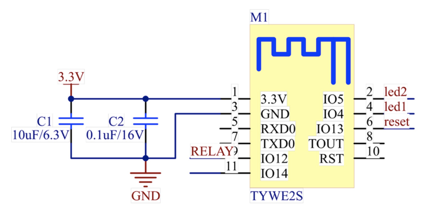
Design specification
Circuit design
| Parameter | Description |
|---|---|
| Power consumption | 3.3V/100 mA. Transient (5 us) current: 450 mA. Recommended supply current is ≥ 300 mA. |
| C1/C2 | Power filter capacitor. They should be arranged near the 3.3V power supply pin. |
| TXD0/RXD0 serial port | The user’s serial port for sending and receiving data. Default baud: 9600, Data bit: 8 bits, Stop bit: 1 bit. No check bit, no flow control. Note: If you need to use this serial port as a general I/O port, contact technicians. |
| TOUT pin | The ADC pin cannot be used as a general I/O port.Note: When not in use, the pin can float. |
| RST pin | The module reset pin, which is active low. A pull-up resistor is included internally, and the pin can float. |
| LED2 pin | Relay status indicator. When the I/O port outputs a low level, the indicator flashes. |
| LED1 pin | Wi-Fi status indicator. When the I/O port outputs a low level, the indicator flashes. |
| Reset button | Active low.
|
| RELAY pin | Coil for control of the relay. The maximum driving capacity of the module I/O port is 12 mA.Note: The I/O driving capacity of the module shall be greater than the driving current required by the relay. |
| Other unused pins | They can float. |
Module antenna
The in-line mode is used by the module by default. In order to optimize the Wi-Fi performance, it is recommended to keep the antenna at least 15 mm from other metal parts.
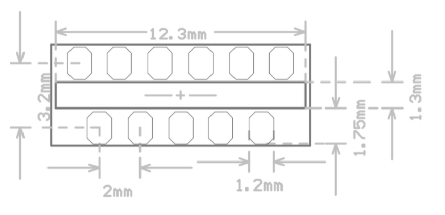
Package description
The recommended plug-in package for the TYWE2S module is as follows.
Is this page helpful?
YesFeedbackIs this page helpful?
YesFeedbackMarketing Cooperation
Business Cooperation
Customer Service
Media Inquiry


