The TYWE3S Module Socket Circuit
Last Updated on : 2024-11-20 02:12:22download
This topic describes the typical circuit design and the package of the TYWE3S module socket.
Typical application diagram
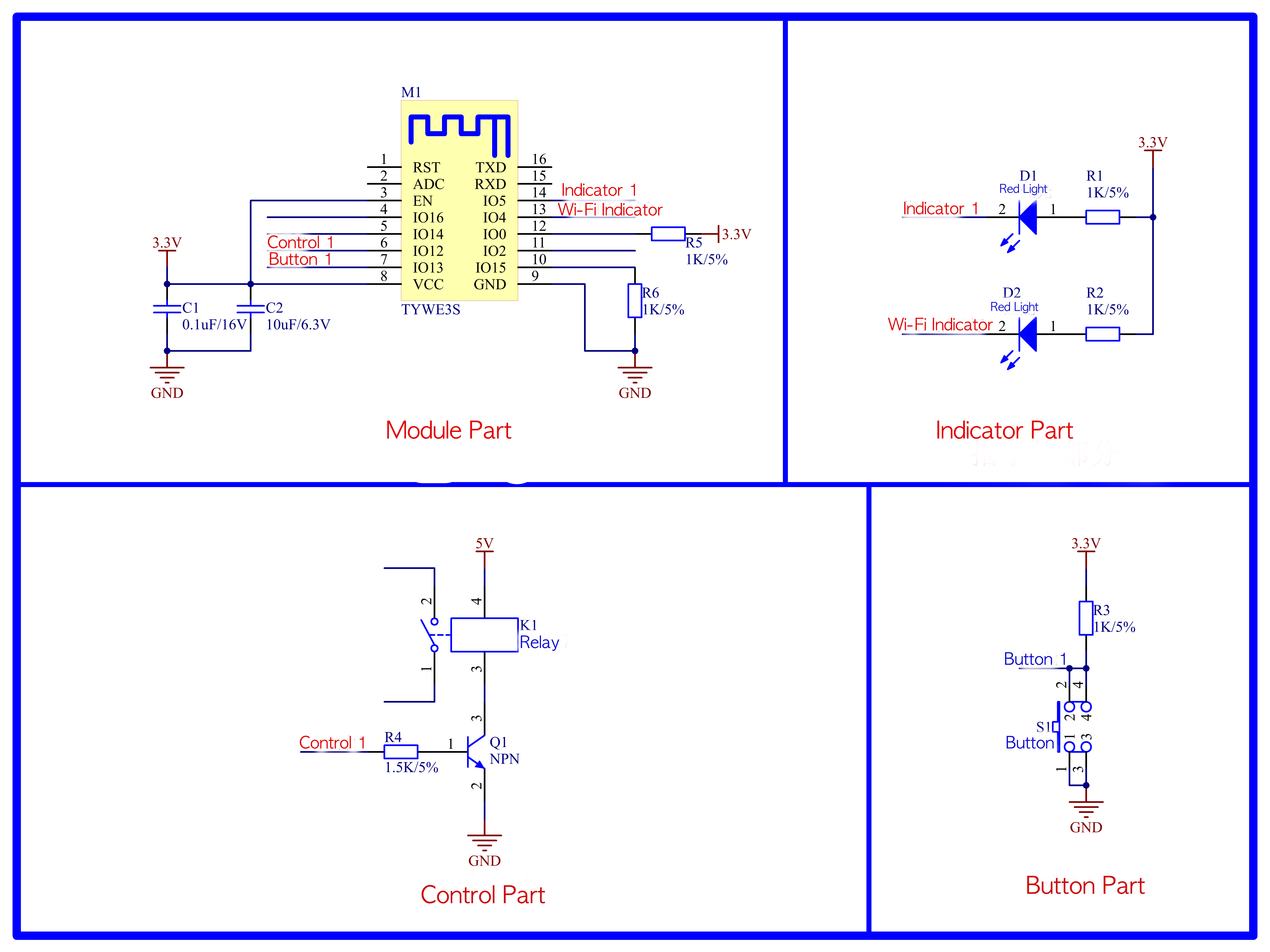
The typical application diagram of the TYWE3S module socket is as follows. 
S1 button is a reset button of the Wi-Fi module, and D2 is a status indicator light of the Wi-Fi module. The relation between the default D2 status for Tuya products and Wi-Fi module working status is as follows.
| D2 status | D2 display | Working status of Wi-Fi module |
|---|---|---|
| Flicker fast | On and off interval is 250 ms | Fast connection mode (SmartConfig mode) |
| Flicker slowly | On and off interval is 1,500 ms | Compatible mode (AP pairing mode) |
| Always on | Always on | Wi-Fi module is connected to the router |
| Always off | Always off | Wi-Fi module is disconnected from the router |
Design specification
Circuit design
| Parameter | Description |
|---|---|
| Power consumption | 3.3V/100 mA. Transient (5 us) current: 450 mA. Recommended supply current is ≥ 300 mA. |
| C1/C2 | Power filter capacitor. The power filter capacitor should be arranged near the VCC pin. |
| TXD/RXD serial port | It is a serial port mode by default.Note: If you need to use this serial port as a general I/O port, contact technicians. |
| ADC pin | The voltage acquisition pin cannot be used as a general I/O port.Note: When not in use, the pin can float. |
| I/O0 pin | This pin takes part in the normal start of the module. During power-on and start, the pin requires a high electrical level to start normally.
|
| I/O2 pin | This pin takes part in the normal start of the module. During power-on and start, it requires a high electrical level to start normally. It is a debugging port of the module by default. Data is output during power-on. It can only be used as an output port. Note: When not in use, the pin can float. |
| I/O15 | This pin takes part in the normal start of the module. During power-on and start, it requires a low electrical level to start normally. A pull-down resistor must be added to the pin. |
| RST pin | The module hardware reset pin, which is active low. |
| I/O16 pin | Avoid any pull-up resistor in the pin while using. |
| LED2 pin | Relay status indicator. |
| LED1 pin | Wi-Fi status indicator. |
| Reset button | Active low.
|
| RELAY pin | Coil for control of the relay. The maximum driving capacity of the module I/O port is 12 mA.Note: The I/O driving capacity of the module shall be greater than the driving current required by the relay. |
| No. 9 to 14 pins | They shall float. |
| Other unused pins | They can float. |
Module antenna
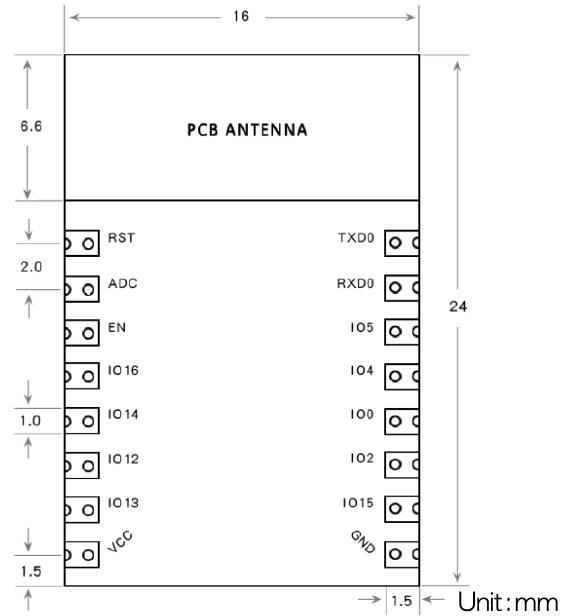
Wiring and copper pour are not allowed below this area of the antenna, and the PCB shall be hollowed out, in order not to affect the antenna performance.
Package description

Is this page helpful?
YesFeedbackIs this page helpful?
YesFeedback


