The TYLC4 Module Stand-Alone Socket
Last Updated on : 2024-06-24 07:53:27Copy for LLMView as MarkdownDownload PDF
This topic describes the typical circuit design and the package of the stand-alone socket with the TYLC4 module.
Typical application diagram
The typical application diagram of the stand-alone socket with the TYLC4 module is as follows. 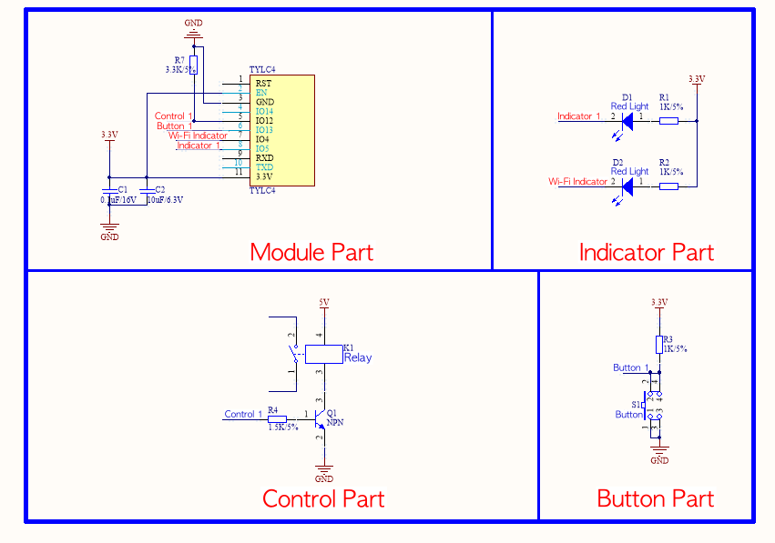
S1 button is a reset button of the Wi-Fi module, and D2 is a status indicator light of the Wi-Fi module. The relation between the default D2 status for Tuya products and Wi-Fi module working status is as follows.
| D2 status | D2 display | Working status of Wi-Fi module |
|---|---|---|
| Flicker fast | On and off interval is 250 ms | Fast connection mode (SmartConfig mode) |
| Flicker slowly | On and off interval is 1,500 ms | Compatible mode (AP pairing mode) |
| Always on | Always on | Wi-Fi module is connected to the router |
| Always off | Always off | Wi-Fi module is disconnected from the router |
Design specification
Circuit design
| Parameter | Description |
|---|---|
| Wi-Fi power consumption | 3.3V/100 mA. When the 3.3V Wi-Fi module is transmitting or receiving RF, the current increases by 50%. For a 3.3V module, the recommended supply current is ≥ 300 mA. The total capacitance value of the external filter capacitor is greater than 10 μF. |
| C1/C2 | Power filter capacitor. The power filter capacitor should be arranged near the VCC pin. |
| TXD/RXD serial port | It is a serial port mode by default.Note: If you need to use this serial port as a general I/O port, contact technicians. |
| RST pin | The module reset pin, which is active low. To use the RST pin, connect it to the I/O port of the MCU. Make sure that the electrical level is matched. |
| Button | Reuse switch function and Wi-Fi reset function.
|
| D2 | Wi-Fi indicator. It indicates the current working status of the Wi-Fi module and smart products. |
| Driver relay pin | The 3.3K pull-down resistor to the ground is required. Otherwise, the relay might be wrongly turned on when the program is not started after power-on. |
| Other unused pins | They can float. |
I/O port specification
| Function | I/O port | Description |
|---|---|---|
| Driver relay | I/O12 | Active high, relay closed |
| Button | I/O13 | Active low |
| Wi-Fi status indicator | I/O4 | Turn on in case of low level |
| Relay status indicator | I/O5 | Turn on in case of low level |
Contact us for the Wi-Fi module of this demo.
Is this page helpful?
YesFeedbackIs this page helpful?
YesFeedbackMarketing Cooperation
Business Cooperation
Customer Service
Media Inquiry


