Wi-Fi Serial Protocol (HomeKit)
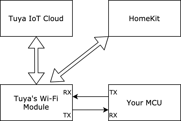
This topic describes how to interface your MCU with Tuya’s Wi-Fi module that can be connected to both the Tuya Developer Platform and the Apple HomeKit platform. After implementing the serial protocol, your product can communicate with Tuya’s Wi-Fi module and interact with 'Powered by Tuya' products and HomeKit-compatible products.
Serial communication
- Baud: 9600
- Data bit: 8
- Parity check: none
- Stop bit: 1
- Data flow control: none
- MCU: microcontroller unit. Your MCU communicates with Tuya’s modules through the serial port.
Frame format
| Field | Bytes | Description |
|---|---|---|
| Header | 2 | It is fixed to 0x55aa. |
| Version | 1 | It is used for updates and extensions. |
| Command | 1 | Frame type |
| Data length | 2 | Big-endian |
| Data | N | Entity data |
| Checksum | 1 | Start from the header, add up all the bytes, and then divide the sum by 256 to get the remainder. |
-
All data greater than one byte is transmitted in big-endian format.
-
Generally, one command is sent by one party and received by the other party synchronously. That is, one party sends a command and waits for a response from the other party. If the sender does not receive a correct response packet within a specified time period, the transmission times out, as shown in the following figure.
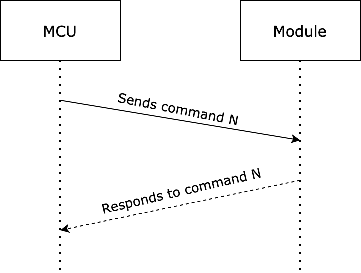
For specific communication modes, see the protocol list in this topic.
-
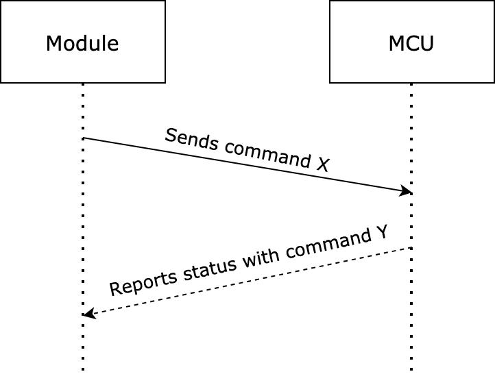
The module sends control commands and the MCU reports data point (DP) status, which occurs asynchronously. Assume that the module sends a command
xand the MCU reports a commandy. The data transmission is as follows.-
The module sends a control command:
-
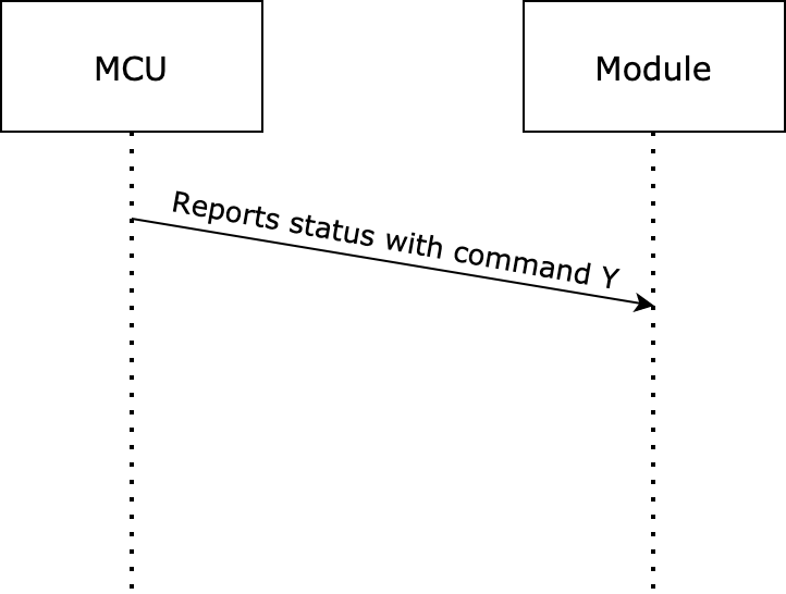
The MCU reports status:
-
Status data unit
The DP command and status data unit are defined as follows:
| Data segment | Bytes | Description |
|---|---|---|
| dpid | 1 | The ID of a DP. |
| type | 1 | The data type of a DP is defined on the Tuya Developer Platform. For more information, see the table of type fields below. |
| len | 2 | The length is the number of bytes of a value. |
| Value | 1/2/4/N | Represented in hexadecimal format. Data greater than one byte is transmitted in big-endian format. |
Type fields
| type | Type | Data length (byte) | Description |
|---|---|---|---|
| 0x00 | Raw | N | Represents a DP of raw data type. The data is passed through the module to the cloud. |
| 0x01 | Boolean | 1 | Represents a DP of Boolean data type. Valid values include 0x00 and 0x01. |
| 0x02 | Value | 4 | Represents a DP of integer type. The data is represented in big-endian format. |
| 0x03 | String | N | Represents a DP of string type. |
| 0x04 | Enum | 1 | Represents a DP of enum type, ranging from 0 to 255. |
| 0x05 | Bitmap | 1/2/4 | Represents a DP of fault type. Data greater than one byte is represented in big-endian format. |
- Except for the
rawdata type, all others belong to the object type. - The status data can contain command data units of multiple DPs.
Protocol list
Send heartbeats
-
After the Wi-Fi module is powered on, it sends heartbeats to the MCU every 15 seconds. If the MCU does not respond within the 3-second timeout period, the module considers the MCU is offline.
-
The MCU can determine whether the module works properly according to the heartbeat. If the module fails to send a heartbeat, the MCU can use the reset pin to reset the module.
The module sends the following command.
| Field | Bytes | Description |
|---|---|---|
| Header | 2 | 0x55aa |
| Version | 1 | 0x00 |
| Command | 1 | 0x00 |
| Data length | 2 | 0x0000 |
| Data | 0 | None |
| Checksum | 1 | Start from the header, add up all the bytes, and then divide the sum by 256 to get the remainder. |
For example, 55 aa 00 00 00 00 ff
The MCU returns the following command.
| Field | Bytes | Description |
|---|---|---|
| Header | 2 | 0x55aa |
| Version | 1 | 0x03 |
| Command | 1 | 0x00 |
| Data length | 2 | 0x0001 |
| Data | 1 | 0x00: The MCU returns this value only one time after a restart. The module uses this value to determine whether the MCU restarts during operation. 0x01: The MCU returns this value except for the first response after a restart. |
| Checksum | 1 | Start from the header, add up all the bytes, and then divide the sum by 256 to get the remainder. |
For example, the MCU returns 55 aa 03 00 00 01 00 03 after a restart.
The MCU returns 55 aa 03 00 00 01 01 04 except for the first response after a restart.
Query product information
Product information consists of the product ID and MCU software version number.
- Product ID (PID): It is automatically generated for each product created on the Tuya Developer Platform for storing product information in the cloud.
- MCU software version format: It is expressed in dot-decimal notation,
x.x.x(0 ≤ x ≤ 99), andxis a decimal digit.
To use the HomeKit capabilities, the Wi-Fi module will send a HomeKit configuration on receiving the response to the production information query. If the MCU is restarted after an OTA update, the Wi-Fi module will send a command to query the MCU and set the working mode of the Wi-Fi module instead of the HomeKit configuration.
The module sends the following command.
| Field | Bytes | Description |
|---|---|---|
| Header | 2 | 0x55aa |
| Version | 1 | 0x00 |
| Command | 1 | 0x01 |
| Data length | 2 | 0x0000 |
| Data | 0 | None |
| Checksum | 1 | Start from the header, add up all the bytes, and then divide the sum by 256 to get the remainder. |
For example, 55 aa 00 01 00 00 00
The MCU returns the following command.
| Field | Bytes | Description |
|---|---|---|
| Header | 2 | 0x55aa |
| Version | 1 | 0x03 |
| Command | 1 | 0x01 |
| Data length | 2 | N |
| Data | N | {"p":"AIp08kLIftb8x***","v":"1.0.0","pt":19} |
| Checksum | 1 | Start from the header, add up all the bytes, and then divide the sum by 256 to get the remainder. |
For example, {"p":"AIp08kLIftb8x***","v":"1.0.0","pt":19}
Field description:
-
pindicates the product ID isAIp08kLIftb8x***, mapping the PID of a product created on the Tuya Developer Platform. (Required) -
vindicates the MCU version is 1.0.0. The version number must be defined in the formatx.x.x. (Required) -
ptindicates the accessory category in HomeKit. For more information, see Appendix 1. (Required)
Query the MCU and set the working mode of the module
-
The working mode indicates how the network status is indicated and the way to trigger module reset. The Wi-Fi module can work in the following two modes.
- The module works with the MCU to process network events. Through serial communication, the module sends the network status to the MCU for LED indication. The MCU can send a command to reset the module when necessary.
- The module processes network events itself. The GPIO pin on the module drives the LED indicator to indicate the network status. The GPIO input signal determines module reset.
-
When the module detects a low level on the GPIO input pin for more than five seconds, it will trigger a reset action. The following command specifies the GPIO pins of the LED indicator and the reset button.
-
For cross-module I/O configuration, the pin number plus 32 makes the pin number we need. For example, the pin number to be set for PB20 is 52 (20 + 32 = 52).
-
The active level setting when the module processes network events itself.
Active low for button press and LED indicator.
Tuya-defined network status
| Network status | Description | Status value |
|---|---|---|
| Status 1 | Waiting for connection | The LED flickers at an interval of 250 milliseconds. |
| Status 2 | The Wi-Fi network has been set up but not connected to the router. | The LED indicator is steady off. |
| Status 3 | The Wi-Fi module has been connected to the router but not to the cloud. | The LED indicator is steady off. |
| Status 4 | The Wi-Fi module has been connected to the cloud. | The LED indicator is steady on. |
HomeKit-defined network status
| Network status | Description | Status value |
|---|---|---|
| Status 1 | To be bound or being bound | The LED flickers at an interval of 250 milliseconds. |
| Status 2 | Not connected | The LED indicator is steady off. |
| Status 3 | Connected | The LED indicator is steady on. |
| Status 4 (special) | A prompt for HomeKit connection, which is fire-and-forget. | The LED indicator flickers three times. |
The module sends the following command.
| Field | Bytes | Description |
|---|---|---|
| Header | 2 | 0x55aa |
| Version | 1 | 0x00 |
| Command | 1 | 0x02 |
| Data length | 2 | 0x0000 |
| Data | 0 | None |
| Checksum | 1 | Start from the header, add up all the bytes, and then divide the sum by 256 to get the remainder. |
For example, 0x55aa 00 02 0000 01
The MCU returns the following command.
| Field | Bytes | Description |
|---|---|---|
| Header | 2 | 0x55aa |
| Version | 1 | 0x03 |
| Command | 1 | 0x02 |
| Data length | 2 | 0x0000: The module works with the MCU to process network events. 0x0003: The module processes network events itself. |
| Data | 0/3 | The data length is 3 bytes: The first byte represents the GPIO pin used to indicate Tuya-defined network status. The second byte represents the GPIO pin used to indicate HomeKit-defined network status. The third byte represents the GPIO pin used to reset the network connection. |
| Checksum | 1 | Start from the header, add up all the bytes, and then divide the sum by 256 to get the remainder. |
For example, the MCU returns 0x55aa 03 02 0000 04 when the module works with the MCU to process network events.
The MCU returns 0x55aa 03 02 0003 0c 0d 0e 2e when the module processes network events itself. 0x0c indicates the LED that signals Tuya-defined network status is connected to GPIO12. 0x0d indicates the LED that signals HomeKit-defined network status is connected to GPIO13. 0x0e indicates the reset button is connected to GPIO14.
Report network status
Tuya-defined network status:
| Network status | Description | Status value |
|---|---|---|
| Status 1 | Waiting for connection | 0x00 |
| Status 2 | The Wi-Fi network has been set up but not connected to the router. | 0x01 |
| Status 3 | The Wi-Fi module has been connected to the router but not to the cloud. | 0x02 |
| Status 4 | The Wi-Fi module has been connected to the cloud. | 0x03 |
HomeKit-defined network status
| Network status | Description | Status value |
|---|---|---|
| Status 1 | To be bound or being bound | 0x00 |
| Status 2 | Not connected | 0x01 |
| Status 3 | Connected | 0x02 |
| Status 4 (special) | A prompt for HomeKit connection, which is fire-and-forget. | 0x03 |
- Note that status 4 is used as a prompt for HomeKit connection, which is fire-and-forget and cannot be used as the indication for network status. The module sends status 4 to notify the MCU that the user sends the identity of a HomeKit accessory. The MCU must return a response within five seconds in a manner such as LED flickering three times or three beeps and after that, the network status must return to its former state. If the Wi-Fi module works in the self-processing mode, the HomeKit-defined LED indicator flickers three times to indicate a HomeKit accessory is recognized.
- When the Wi-Fi module detects the MCU is restarted or disconnected and then goes online, it actively sends the network status to the MCU.
- When the Wi-Fi network status changes, the Wi-Fi module sends the current status to the MCU.
- The network status flag is used to distinguish Tuya-defined network status and HomeKit-defined network status.
- If you choose the module self-processing mode, implementing this protocol for your MCU is not necessary.
The module sends the following command.
| Field | Bytes | Description |
|---|---|---|
| Header | 2 | 0x55aa |
| Version | 1 | 0x00 |
| Command | 1 | 0x03 |
| Data length | 2 | 0x0002 |
| Data | 1 | The network status flag: 0x00: Tuya-defined network status 0x01: HomeKit-defined network status |
| 1 | For Tuya-defined network status: 0x00: status 1 0x01: status 2 0x02: status 3 0x03: status 4 For HomeKit-defined network status: 0x00: status 1 0x01: status 2 0x02: status 3 0x03: status 4 (special) |
|
| Checksum | 1 | Start from the header, add up all the bytes, and then divide the sum by 256 to get the remainder. |
The MCU returns the following command.
| Field | Bytes | Description |
|---|---|---|
| Header | 2 | 0x55aa |
| Version | 1 | 0x03 |
| Command | 1 | 0x03 |
| Data length | 2 | 0x0000 |
| Data | 0 | None |
| Checksum | 1 | Start from the header, add up all the bytes, and then divide the sum by 256 to get the remainder. |
Reset Wi-Fi connection
-
A HomeKit accessory that has been added to the Tuya app still can be added to the Home app on an iOS device that is connected to the same LAN. If a HomeKit accessory has been added to the Home app, it can only be added to the Tuya app over Bluetooth.
-
About binding and reset
-
If a HomeKit accessory is removed from the Home app, this accessory is still connected to the LAN and can be bound again without the pairing process.
-
If a HomeKit accessory is added to the Home app and then bound with the Tuya app, both apps can control this accessory. If this accessory is removed from the Tuya app and restarted, it can still be bound with the Tuya app because the pairing with the Home app is still established.
-
If a HomeKit accessory is added to the Home app and then bound with the Tuya app, both apps can control this accessory. If this accessory is removed from the Home app and not restarted, it can still be bound with the Home app because the pairing with Tuya app is still established.
-
If a HomeKit accessory is removed from the Tuya app on an Android device, it enters the status of waiting for a connection.
-
If a HomeKit accessory is added to the Tuya app on an Android device and then added to the Home app, this accessory can still be controlled with the Home app even if it is removed from the Tuya app.
-
-
When the module detects a low level on the GPIO input pin for more than five seconds, it will trigger a reset action. If you choose the module self-processing mode, implementing this protocol for your MCU is not necessary.
The MCU sends the following command.
| Field | Bytes | Description |
|---|---|---|
| Header | 2 | 0x55aa |
| Version | 1 | 0x03 |
| Command | 1 | 0x04 |
| Data length | 2 | 0x0000 |
| Data | 0 | None |
| Checksum | 1 | Start from the header, add up all the bytes, and then divide the sum by 256 to get the remainder. |
For example, 55 aa 03 04 00 00 06
The module returns the following command.
| Field | Bytes | Description |
|---|---|---|
| Header | 2 | 0x55aa |
| Version | 1 | 0x00 |
| Command | 1 | 0x04 |
| Data length | 2 | 0x0000 |
| Data | 0 | None |
| Checksum | 1 | Start from the header, add up all the bytes, and then divide the sum by 256 to get the remainder. |
For example, 55 aa 00 04 00 00 03
Send commands
-
The command sent by the module can contain status data units of multiple DPs.
-
The module sends control commands and the MCU reports DP status, which occurs asynchronously.
The module sends the following command.
| Field | Bytes | Description |
|---|---|---|
| Header | 2 | 0x55aa |
| Version | 1 | 0x00 |
| Command | 1 | 0x06 |
| Data length | 2 | Depends on the type and number of command data units. |
| Data | N | Status data units |
| Checksum | 1 | Start from the header, add up all the bytes, and then divide the sum by 256 to get the remainder. |
For example, the DP 3 of on/off control is of Boolean data type. If the value is 1, it indicates switching on the device.
55 aa 00 06 00 05 03 01 00 01 01 10
Report status
-
For more information about the data unit, see Status data unit.
-
The MCU asynchronously reports DP status, which can be triggered by three mechanisms.
- After the MCU executes the command received from the module, it reports the changed DP status to the module.
- When the MCU actively detects status changes of DPs, it sends the changed DP status to the module.
- When the MCU receives the DP status query, it sends the status of all DPs to the module.
-
The MCU can report status data units of multiple DPs.
The MCU sends the following command.
| Field | Bytes | Description |
|---|---|---|
| Header | 2 | 0x55aa |
| Version | 1 | 0x03 |
| Command | 1 | 0x07 |
| Data length | 2 | It depends on types and the number of status data units. |
| Data | N | Status data units |
| Checksum | 1 | Start from the header, add up all the bytes, and then divide the sum by 256 to get the remainder. |
For example, the DP 5 of humidity is of value data type. If the current humidity is 30%, the MCU sends the following command to the module.
55 aa 03 07 00 08 05 02 00 04 00 00 00 1e 3a
Report status data units of multiple DPs
The DP 109 is of Boolean data type, and its value is 1.
The DP 102 is of string data type, and its value is 201804121507. The value is transferred in ASCII mode.
55 aa 03 07 00 15 6d 01 00 01 01 66 03 00 0c 32 30 31 38 30 34 31 32 31 35 30 37 62
Query DP status
-
The module asynchronously queries the status of all object DPs. When the MCU receives queries, it sends the status of DPs to the module. For more information, see Report status.
-
When the MCU receives this command, it must report status to both the Tuya app and the Home app. Otherwise, the device status on these two apps will not be consistent.
-
The module sends DP status queries when the following two events occur.
- When powered on for the first time, the module builds communication with the MCU and then sends status queries.
- When the module detects the MCU is restarted or disconnected and then goes online, the module sends status queries.
The module sends the following command.
| Field | Bytes | Description |
|---|---|---|
| Header | 2 | 0x55aa |
| Version | 1 | 0x00 |
| Command | 1 | 0x08 |
| Data length | 2 | 0x0000 |
| Data | 0 | None |
| Checksum | 1 | Start from the header, add up all the bytes, and then divide the sum by 256 to get the remainder. |
For example, 55 aa 00 08 00 00 07
Update MCU firmware
-
You can specify the update method for OTA MCU firmware updates. The module only serves as the channel for OTA data transmission, without any data parsing operation.
-
The Tuya Developer Platform provides four update methods.
- Update notification: Users receive a firmware update notification on the app and choose whether to install updates.
- Automatic update: Users will not receive any update pop-up window. The module checks for firmware updates within one minute after power-on. If any new version is available, it will automatically pull the updates. The module checks for updates every 24 hours after the first-time power-on.
- Forced update:
Users receive a firmware update notification on the app and have no option but to update the firmware. - Check for updates: Users will not receive a firmware update notification on the app but need to manually check for new updates.
-
The following flowchart shows how the OTA firmware update works.
After the module has sent all update packages, it will send the command0x01to query the product information. The MCU must reply with the new MCU firmware version number within one minute. The new version number should be consistent with that configured on the Tuya Developer Platform.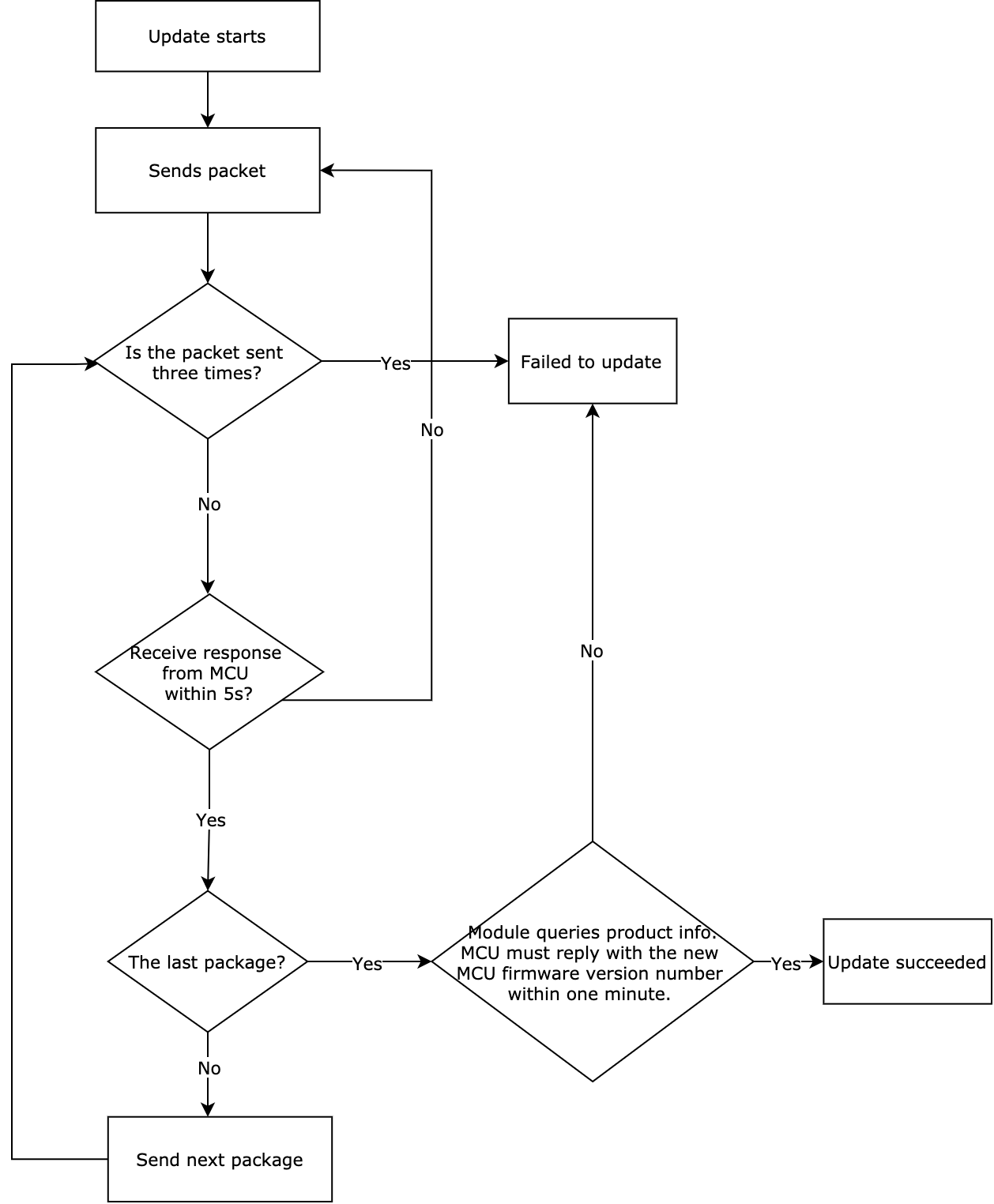
Start OTA update
The OTA update can be initiated automatically or manually. For automatic updates, when the module detects MCU firmware updates from the cloud, the transmission of the update package automatically starts. For manual updates, the module initiates updates only when updates are confirmed on the app.
The module sends the following command.
| Field | Bytes | Description |
|---|---|---|
| Header | 2 | 0x55aa |
| Version | 1 | 0x00 |
| Command | 1 | 0x0a |
| Data length | 2 | 0x0004 |
| Data | 4 | The size of the update package. The data type is an unsigned integer, and the data is stored in big-endian format. |
| Checksum | 1 | Start from the header, add up all the bytes, and then divide the sum by 256 to get the remainder. |
For example, 55 aa 00 0a 00 04 00 00 68 00 75
It indicates the size of the update package is 26624 bytes, namely 26 KB.
The MCU returns the following command.
| Field | Bytes | Description |
|---|---|---|
| Header | 2 | 0x55aa |
| Version | 1 | 0x03 |
| Command | 1 | 0x0a |
| Data length | 2 | 0x0001 |
| Data | 1 | The update package size of a single packet: 0x00: 256 bytes by default, compatible with legacy firmware 0x01: 512 bytes 0x02: 1024 bytes |
| Checksum | 1 | Start from the header, add up all the bytes, and then divide the sum by 256 to get the remainder. |
For example, 55 aa 03 0a 00 01 00 0d
Transmit update package
-
The data format of update package transmission: packet offset + packet data.
-
If the MCU receives the frame with a data length equal to 4 bytes and the packet offset is equal to or greater than the size of firmware, the transmission ends.
The module sends the following command.
| Field | Bytes | Description |
|---|---|---|
| Header | 2 | 0x55aa |
| Version | 1 | 0x00 |
| Command | 1 | 0x0b |
| Data length | 2 | The data length is the sum of 0x0004 and the packet length. |
| Data | N | The first four bytes are fixed as packet offset, and the latter bytes are the packet data. |
| Checksum | 1 | Start from the header, add up all the bytes, and then divide the sum by 256 to get the remainder. |
For example,
The size of the update file is 530 bytes. The MCU can skip the response to the last packet.
- For the first packet, the packet offset is
0x00000000, and the packet length is 256 bytes.
55 aa 00 0b 01 04 00000000 xx…xx XX - For the second packet, the packet offset is
0x00000100, and the packet length is 256 bytes.
55 aa 00 0b 01 04 00000100 xx…xx XX - For the third packet, the packet offset is
0x00000200, and the packet length is 18 bytes.
55 aa 00 0b 00 16 00000200 xx…xx XX - For the last packet, the packet offset is
0x00000212, and the packet length is 0 bytes.
55 aa 00 0b 00 04 00000212 xx…xx XX
The MCU returns the following command.
| Field | Bytes | Description |
|---|---|---|
| Header | 2 | 0x55aa |
| Version | 1 | 0x03 |
| Command | 1 | 0x0b |
| Data length | 2 | 0x0000 |
| Data | 0 | None |
| Checksum | 1 | Start from the header, add up all the bytes, and then divide the sum by 256 to get the remainder. |
For example, 55 aa 03 0b 00 00 0d
Get system time in GMT
-
As the international standard of civil time, GMT is independent of the time zone and DST.
-
After connecting to the network, the module returns success and valid time data after the local timestamp is synced.
The MCU sends the following command.
| Field | Bytes | Description |
|---|---|---|
| Header | 2 | 0x55aa |
| Version | 1 | 0x03 |
| Command | 1 | 0x0c |
| Data length | 2 | 0x0000 |
| Data | 0 | None |
| Checksum | 1 | Start from the header, add up all the bytes, and then divide the sum by 256 to get the remainder. |
For example, 55 aa 03 0c 00 00 0e
The module returns the following command.
| Field | Bytes | Description |
|---|---|---|
| Header | 2 | 0x55aa |
| Version | 1 | 0x00 |
| Command | 1 | 0x0c |
| Data length | 2 | 0x0007 |
| Data | 7 | The data length is 7 bytes. Data[0]: indicates whether the system time is obtained successfully. 0: failure. 1: success. Data[1]: indicates the year. For example, 0x00 indicates the year 2000. Data[2]: indicates the month, ranging from 1 to 12. Data[3]: indicates the day, ranging from 1 to 31. Data[4]: indicates the hour, ranging from 0 to 23. Data[5]: indicates the minute, ranging from 0 to 59. Data[6]: indicates the second, ranging from 0 to 59. |
| Checksum | 1 | Start from the header, add up all the bytes, and then divide the sum by 256 to get the remainder. |
For example, if the system time is 05:06:07 on April 19, 2016 (GMT), the module will return the following command.
55 aa 00 0c 00 07 01 10 04 13 05 06 07 4c
Get local time
-
The local time is calculated by adding the time zone offset and DST to the GMT. The time zone is where the device is activated.
-
After connecting to the network, the module returns success and valid time data after the local timestamp is synced.
The MCU sends the following command.
| Field | Bytes | Description |
|---|---|---|
| Header | 2 | 0x55aa |
| Version | 1 | 0x03 |
| Command | 1 | 0x1c |
| Data length | 2 | 0x0000 |
| Data | xxxx | None |
| Checksum | 1 | Start from the header, add up all the bytes, and then divide the sum by 256 to get the remainder. |
The module returns the following command.
| Field | Bytes | Description |
|---|---|---|
| Header | 2 | 0x55aa |
| Version | 1 | 0x00 |
| Command | 1 | 0x1c |
| Data length | 2 | 0x0008 |
| Data | Data | The data length is 8 bytes. Data[0]: indicates whether the local time is obtained successfully. 0: failure. 1: success. Data[1]: indicates the year. For example, 0X00 indicates the year 2000. Data[2]: indicates the month, ranging from 1 to 12. Data[3]: indicates the day, ranging from 1 to 31. Data[4]: indicates the hour, ranging from 0 to 23. Data[5]: indicates the minute, ranging from 0 to 59. Data[6]: indicates the second, ranging from 0 to 59. Data[7]: indicates the week, ranging from 1 to 7. 1 indicates Monday. |
| Checksum | 1 | Start from the header, add up all the bytes, and then divide the sum by 256 to get the remainder. |
-
If the device is activated in mainland China, the local time is Beijing time (GMT+08:00).
For example, if the local time is 05:06:07 on April 19, 2016 (GMT+08:00), the module will return the following command.
55 aa 00 1c 00 08 01 10 04 13 05 06 07 02 5f -
If the device is activated in other countries or regions, the local time is the time zone in which the device is located.
Test Wi-Fi functionality
-
The module scans the router whose SSID is
tuya_mdev_testand returns the result and signal strength in percentage. -
To prevent quality defects, it is recommended that the distance between the router and the device under test should be about 5 meters. If the signal strength is greater than or equal to 60%, the device is acceptable. The specific testing conditions depend on your production line and environment.
The MCU sends the following command.
| Field | Bytes | Description |
|---|---|---|
| Header | 2 | 0x55aa |
| Version | 1 | 0x03 |
| Command | 1 | 0x0e |
| Data length | 2 | 0x0000 |
| Data | Data | None |
| Checksum | 1 | Start from the header, add up all the bytes, and then divide the sum by 256 to get the remainder. |
The module returns the following command.
| Field | Bytes | Description |
|---|---|---|
| Header | 2 | 0x55aa |
| Version | 1 | 0x00 |
| Command | 1 | 0x0e |
| Data length | 2 | 0x0002 |
| Data | 2 | The data length is 2 bytes. Data[0]: 0x00 indicates failure and 0x01 indicates success. If Data[0] is 0x01, Data[1] indicates the signal strength, ranging from 0 to 100, 0 for the weakest and 100 for the strongest. If Data[0] is 0x00, Data[1] indicates failure reasons. 0x00 indicates the specified SSID is not found. 0x01 indicates the authorization key is not flashed to the module. |
| Checksum | 1 | Start from the header, add up all the bytes, and then divide the sum by 256 to get the remainder. |
Get module’s memory
Get the remaining memory of the Wi-Fi module.
The MCU sends the following command.
| Field | Bytes | Description |
|---|---|---|
| Header | 2 | 0x55aa |
| Version | 1 | 0x03 |
| Command | 1 | 0x0f |
| Data length | 2 | 0x0000 |
| Data | Data | None |
| Checksum | 1 | Start from the header, add up all the bytes, and then divide the sum by 256 to get the remainder. |
The module returns the following command.
| Field | Bytes | Description |
|---|---|---|
| Header | 2 | 0x55aa |
| Version | 1 | 0x00 |
| Command | 1 | 0x0f |
| Data length | 2 | 0x0004 |
| Data | 4 | The data length is 4 bytes. The value is represented in big-endian format. For example, 0x00 0x00 0x28 0x00 represents 10240 bytes remaining memory. |
| Checksum | 1 | Start from the header, add up all the bytes, and then divide the sum by 256 to get the remainder. |
Get Wi-Fi signal strength (optional)
The MCU sends the following command.
| Field | Bytes | Description |
|---|---|---|
| Header | 2 | 0x55aa |
| Version | 1 | 0x03 |
| Command | 1 | 0x24 |
| Data length | 2 | 0 |
| Data | N | None |
| Checksum | 1 | Start from the header, add up all the bytes, and then divide the sum by 256 to get the remainder. |
The module returns the following command.
| Field | Bytes | Description |
|---|---|---|
| Header | 2 | 0x55aa |
| Version | 1 | 0x00 |
| Command | 1 | 0x24 |
| Data length | 2 | 0x0001 |
| Data | Data | 0x00: failure. A value less than 0: indicates signal strength, such as -60 dB. |
| Checksum | 1 | Start from the header, add up all the bytes, and then divide the sum by 256 to get the remainder. |
Notify the module to disable heartbeat (optional)
The MCU sends the following command.
| Field | Bytes | Description |
|---|---|---|
| Header | 2 | 0x55aa |
| Version | 1 | 0x03 |
| Command | 1 | 0x25 |
| Data length | 2 | 0 |
| Data | N | None |
| Checksum | 1 | Start from the header, add up all the bytes, and then divide the sum by 256 to get the remainder. |
The module returns the following command.
| Field | Bytes | Description |
|---|---|---|
| Header | 2 | 0x55aa |
| Version | 1 | 0x00 |
| Command | 1 | 0x25 |
| Data length | 2 | 0 |
| Data | N | None |
| Checksum | 1 | Start from the header, add up all the bytes, and then divide the sum by 256 to get the remainder. |
Before the module goes to sleep for reducing power consumption, the MCU can send this command to notify the module to disable the heartbeat. Because heartbeats are required for building communication between the module and the MCU, this command must not be sent when the device is just powered on.
Get Wi-Fi status
The MCU sends the following command.
| Field | Bytes | Description |
|---|---|---|
| Header | 2 | 0x55aa |
| Version | 1 | 0x03 |
| Command | 1 | 0x2B |
| Data length | 2 | 0x0000 |
| Data | Data | None |
| Checksum | 1 | Start from the header, add up all the bytes, and then divide the sum by 256 to get the remainder. |
The module returns the following command.
| Field | Bytes | Description |
|---|---|---|
| Header | 2 | 0x55aa |
| Version | 1 | 0x00 |
| Command | 1 | 0x2B |
| Data length | 2 | 0x0001 |
| Data | 1 | The protocol must be consistent with that described in Report network status. |
| Checksum | 1 | Start from the header, add up all the bytes, and then divide the sum by 256 to get the remainder. |
Get module’s MAC address
The MCU sends the following command.
| Field | Bytes | Description |
|---|---|---|
| Header | 2 | 0x55aa |
| Version | 1 | 0x03 |
| Command | 1 | 0x2d |
| Data length | 2 | 0x0000 |
| Data | Data | None |
| Checksum | 1 | Start from the header, add up all the bytes, and then divide the sum by 256 to get the remainder. |
The module returns the following command.
| Field | Bytes | Description |
|---|---|---|
| Header | 2 | 0x55aa |
| Version | 1 | 0x00 |
| Command | 1 | 0x2d |
| Data length | 2 | 0x0007 |
| Data | Data | Data[0]: indicates whether the MAC address is obtained successfully. 0x00 indicates success and the next 6 bytes denote a valid MAC address. 0x01 indicates failure and the next 6 bytes denote an invalid MAC address. Data[1] to Data[6]: indicates the valid MAC address of the module on a success. |
| Checksum | 1 | Start from the header, add up all the bytes, and then divide the sum by 256 to get the remainder. |
Extended services
Get information about Wi-Fi module
-
The running data of the Wi-Fi module is required for some products. This field is used to get the required information.
-
The MCU can send a specified code to the module to get the required information. If the MCU requires multiple types of information, the codes must be sent in order.
-
If the MCU requires all the information available, it can use the code
0xff.
- The data format of this field is in JSON string and the data length varies depending on the information type.
- The length of data that the MCU sends to the module must be at least 2 bytes, namely the sub-command plus a 1-byte data code. If the data length is incorrect, the module will return a failure.
- The data codes have a one-to-one relationship with the information types. Make sure you use the correct data code and do not use the reserved code.
- For more information about the returned fields, see Appendix 4.
The MCU sends the following command.
| Field | Length | Description |
|---|---|---|
| Header | 2 | 0x55aa |
| Version | 1 | 0x03 |
| Command | 1 | 0x34 |
| Data length | 2 | 0x01+0x01+…N |
| Data | 1 | Sub-command: 0x07 |
| Data(1) | 0x01: reserved 0x02: the country code 0x03: the serial number of the module …… 0xFF: get all the information available. This code is valid only when it is set as the first byte and enjoys the highest priority. When the module receives this code, it will return all the information available. |
|
| Data(2) | 0x01: reserved 0x02: the country code 0x03: the serial number of the module …… |
|
| Data(N) | 0x01: reserved 0x02: the country code 0x03: the serial number of the module …… |
|
| Checksum | 1 | Start from the header, add up all the bytes, and then divide the sum by 256 to get the remainder. |
For example, 55 AA 03 34 00 02 07 02 41
The module returns the following command.
| Field | Bytes | Description |
|---|---|---|
| Header | 2 | 0x55aa |
| Version | 1 | 0x00 |
| Command | 1 | 0x34 |
| Data length | 2 | 0x02+N |
| Data | 1 | 0x07 (sub-command) |
| 1 | The result: 0x00: success. 0x01: failure. No subsequent data will be returned. |
|
| { "cc" :xx, "sn":"xxx" } |
cc: country code (optional) sn: the serial number of the module (optional) |
|
| Checksum | 1 | Start from the header, add up all the bytes, and then divide the sum by 256 to get the remainder. |
HomeKit capabilities
This section and the followings describe commands specific to the HomeKit accessory.
Initialization process
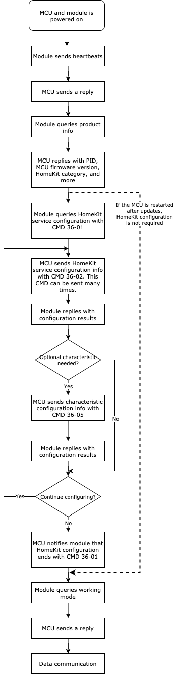
The time from sending a heartbeat to receiving working mode should not exceed three seconds.
HomeKit status data unit
| Data segment | Bytes | Description | |
|---|---|---|---|
| Service serial number | 1 | The MCU sends the service serial number to the module when the service configuration is performed. | |
| Length of the characteristic string identifier | 1 | Length of the characteristic string identifier | |
| Characteristic string identifier | n | For more information about the characteristic string identifier, see Appendix 3. | |
| type | 1 | The data type. For more information, see the table of Type fields below. | |
| len | 2 | The length is the number of bytes of a value. | |
| Value | 1/2/4/N | Represented in hexadecimal format. Data greater than one byte is transmitted in big-endian format. |
Type fields
| Type | Value | Length (byte) | Description |
|---|---|---|---|
| Boolean | 0x00 | 1 | Represents Boolean data type. Valid values include 0x00 and 0x01. |
| uint | 0x01 | 4 | Represents unsigned integer type (uint8, uint16, and uint32) in big-endian format. |
| int | 0x02 | 4 | Represents signed integer type in big-endian format. |
| 64bit uint | 0x03 | 8 | Represents unsigned integer type (uint64) in big-endian format. |
| float | 0x04 | 4 | Represents floating point data type. The first two bytes contain the integer and the last two bytes contain the decimal. |
| String | 0x05 | N | Represents string data type. |
| Raw | 0x06 | N | Represents raw data for transparent transmission. |
Query HomeKit service configuration
-
The module sends this command to flag the start of the HomeKit configuration. When the MCU receives this command, it sends the required information for configuring HomeKit services and characteristics.
-
After sending all the required information, the MCU returns the response to this command.
The module sends the following command.
| Field | Bytes | Description |
|---|---|---|
| Header | 2 | 0x55aa |
| Version | 1 | 0x00 |
| Command | 1 | 0x36 |
| Data length | 2 | 0x0001 |
| Data | 1 | 0x01 (sub-command) |
| Checksum | 1 | Start from the header, add up all the bytes, and then divide the sum by 256 to get the remainder. |
The MCU returns the following command.
| Field | Bytes | Description |
|---|---|---|
| Header | 2 | 0x55aa |
| Version | 1 | 0x03 |
| Command | 1 | 0x36 |
| Data length | 2 | 0x0001 |
| Data | 1 | 0x01 (sub-command) |
| Checksum | 1 | Start from the header, add up all the bytes, and then divide the sum by 256 to get the remainder. |
HomeKit service configuration
-
The MCU must send this command before the module working mode query and after the product information query.
-
You can configure multiple identical HomeKit services for one accessory and use the service serial number to distinguish between them. The service serial number is also used to manage different HomeKit services.
-
An accessory can have multiple different services, which might be linked to each other. You should specify one of the available services as the primary service that must match the primary function of the accessory and also match with the accessory category. The primary service must be stored first in the service array.
-
The service serial number is used for sending or reporting HomeKit commands.
-
Each service contains one or more characteristics. A characteristic is a feature that represents data or an associated behavior of a service. The Wi-Fi module will add the required characteristic automatically. For more information about HomeKit characteristics, see Appendix 3. To add the optional characteristics, the MCU should send the command Optional characteristic configuration.
The MCU sends the following command.
| Field | Bytes | Description | |
|---|---|---|---|
| Header | 2 | 0x55aa | |
| Version | 1 | 0x03 | |
| Command | 1 | 0x36 | |
| Data length | 2 | 0x0001+2N+M1+M2+…+Mn | |
| Data | 1 | 0x02 (sub-command) | |
| The first service. | 1 | The service serial number. It can start with zero, with an increment of 1 for each newly added service. | |
| 1 | |||
| M1 | The service string identifier. For more information, see Appendix 2. | ||
| The second service. | 1 | Service serial number | |
| 1 | The length of service string identifier | ||
| M2 | The service string identifier. For more information, see Appendix 2. | ||
| - | - | - | |
| The Nth service. | 1 | Service serial number | |
| 1 | The length of service string identifier | ||
| Mn | The service string identifier. For more information, see Appendix 2. | ||
| Checksum | 1 | Start from the header, add up all the bytes, and then divide the sum by 256 to get the remainder. |
The module returns the following command.
| Field | Bytes | Description |
|---|---|---|
| Header | 2 | 0x55aa |
| Version | 1 | 0x00 |
| Command | 1 | 0x36 |
| Data length | 2 | 0x0002+N or 0x0002 |
| Data | 1 | 0x02 (sub-command) |
| 1 | The result of data processing. 0x00: success. The returned result of subsequent service configuration is valid. 0x01: failure. No result of service configuration will be returned. |
|
| N | The result of configuring the first service. 0x00: success. 0x01: failure. |
|
| The result of configuring the second service. | ||
| - | ||
| The result of configuring the Nth service. | ||
| Checksum | 1 | Start from the header, add up all the bytes, and then divide the sum by 256 to get the remainder. |
Send HomeKit commands
For more information about HomeKit commands, see HomeKit status data unit.
The module sends the following command.
| Field | Bytes | Description |
|---|---|---|
| Header | 2 | 0x55aa |
| Version | 1 | 0x00 |
| Command | 1 | 0x36 |
| Data length | 2 | 0x0001+N |
| Data | 1 | 0x03 (sub-command) |
| N | HomeKit status data unit | |
| Checksum | 1 | Start from the header, add up all the bytes, and then divide the sum by 256 to get the remainder. |
Report HomeKit status
-
For more information about HomeKit commands, see HomeKit status data unit.
-
The MCU asynchronously reports HomeKit status, which can be triggered by three mechanisms.
- After the MCU executes a HomeKit command, it will report the current status of the corresponding HomeKit characteristic to the Wi-Fi module.
- When the MCU proactively detects status changes of HomeKit characteristics, it will report the current status of the corresponding characteristic to the Wi-Fi module.
- When the MCU receives the status query, it will report the status of all the HomeKit characteristics to the Wi-Fi module.
-
The MCU can report the status of multiple HomeKit status data units at a time.
The MCU sends the following command.
| Field | Bytes | Description |
|---|---|---|
| Header | 2 | 0x55aa |
| Version | 1 | 0x03 |
| Command | 1 | 0x36 |
| Data length | 2 | 0x0001+N |
| Data | 1 | 0x04 (sub-command) |
| N | HomeKit status data unit | |
| Checksum | 1 | Start from the header, add up all the bytes, and then divide the sum by 256 to get the remainder. |
Optional characteristic configuration (optional)
-
Each HomeKit service includes required and optional characteristics. The Wi-Fi module adds the required characteristic automatically. To add the optional characteristic, the MCU must send this command.
-
If the MCU receives a result of successful service configuration from the Wi-Fi module, it can send this command to configure the optional characteristics.
-
If the MCU does not send this command, the registered services only include the required characteristics.
-
This command must be sent before the MCU sends a response to the HomeKit service configuration query.
The MCU sends the following command.
| Field | Bytes | Description | |
|---|---|---|---|
| Header | 2 | 0x55aa | |
| Version | 1 | 0x03 | |
| Command | 1 | 0x36 | |
| Data length | 2 | 0x0001+2N+M1+M2+…+Mn | |
| Data | 1 | 0x05 (sub-command) | |
| 1 | The service serial number. Corresponds to HomeKit service configuration. | ||
| The first optional characteristic. | 1 | Length of the optional characteristic string identifier | |
| M1 | For more information about the characteristic string identifier, see Appendix 3. | ||
| The second optional characteristic. | 1 | Length of the optional characteristic string identifier | |
| M2 | For more information about the characteristic string identifier, see Appendix 3. | ||
| - | - | - | |
| The Nth optional characteristic. | 1 | Length of the optional characteristic string identifier | |
| Mn | For more information about the characteristic string identifier, see Appendix 3. | ||
| Checksum | 1 | Start from the header, add up all the bytes, and then divide the sum by 256 to get the remainder. |
The module returns the following command.
| Field | Bytes | Description |
|---|---|---|
| Header | 2 | 0x55aa |
| Version | 1 | 0x00 |
| Command | 1 | 0x36 |
| Data length | 2 | 0x0002+N or 0x0002 |
| Data | 1 | 0x05 (sub-command) |
| 1 | The result of data processing. 0x00: success. The returned result of subsequent optional characteristic configuration is valid. 0x01: failure. No result of optional characteristic configuration will be returned. |
|
| N | The result of configuring the first optional characteristic. 0x00: success. 0x01: failure. |
|
| The result of configuring the second optional characteristic. | ||
| - | ||
| The result of configuring the Nth optional characteristic. | ||
| Checksum | 1 | Start from the header, add up all the bytes, and then divide the sum by 256 to get the remainder. |
Valid values of characteristic (optional)
-
You can use this command to configure valid values of characteristics.
-
For example, the characteristic of the current air purifier state has three valid values by default, namely
0 Inactive,1 Idle, and2 Purifying Air. If1 Idleis not needed, the MCU can send this command to configure the valid values as0 Inactiveand2 Purifying Air. -
This command must be sent after service and characteristic configuration and before the MCU sends a response to the command
36-01. -
If the MCU does not send this command, the Wi-Fi module will register the default valid values.
-
This command only applies to HomeKit characteristics of uint8 format.
If a characteristic does not contain a valid value that has not been removed through the configuration process, the test for HomeKit certification might fail.
The MCU sends the following command.
| Field | Bytes | Description |
|---|---|---|
| Header | 2 | 0x55aa |
| Version | 1 | 0x03 |
| Command | 1 | 0x36 |
| Data length | 2 | 0x0001+N |
| Data | 1 | 0x06 (sub-command) |
| { "service_serial":xx, "char_str":"xx", "val_type":xx, "valid_val":[xx,xx,xx] } |
service_serial: the serial number of the service that the characteristic belongs to. char_str: the string identifier of the characteristic. val_type: the value type of the characteristic. 0: The valid value can be changed. This type applies to characteristics such as current air purifier state and air quality. 1: The range of the valid value can be changed. This type applies to characteristics such as rotation speed and PM2.5 density. Others: reserved. valid_value: stored in an array. If val_type is set to 0, the element in an array is the list of valid values. The number of elements depends on the number of valid values. If val_type is set to 1, the elements in an array are the minimum value and maximum value of the updated value range. There are two elements: the first one is the minimum value and the second one is the maximum value. |
|
| Checksum | 1 | Start from the header, add up all the bytes, and then divide the sum by 256 to get the remainder. |
For example, if the service_serial of the air purifier is 0, to remove the valid value of 1 Idle, the MCU sends the following command.
55 AA 03 36 00 44 06 7B 22 73 65 72 76 69 63 65 5F 73 65 72 69 61 6C 22 3A 30 2C 22 63 68 61 72 5F 73 74 72 22 3A 22 41 39 22 2C 22 76 61 6C 5F 74 79 70 65 22 3A 30 2C 22 76 61 6C 69 64 5F 76 61 6C 22 3A 5B 30 2C 32 5D 7D 96
The module returns the following command.
| Field | Bytes | Description |
|---|---|---|
| Header | 2 | 0x55aa |
| Version | 1 | 0x00 |
| Command | 1 | 0x36 |
| Data length | 2 | 0x0002 |
| Data | 1 | 0x06 (sub-command) |
| 1 | The result of data processing. 0x00: success. 0x01: failure. service_serial not found. 0x02: failure. char_str not found. 0x03: failure. val_type not supported. 0x04: failure. valid_val not configured correctly. 0x05: failure. Incorrect parameter. 0x06: failure. Configuration is not available currently. 0x07: failure. Failed to process data. Others: reserved |
|
| Checksum | 1 | Start from the header, add up all the bytes, and then divide the sum by 256 to get the remainder. |
Notify new feature configuration
-
The MCU sends this command to notify the module of the new feature configuration after the accessory is powered on and before the command
0x02is sent. -
The MCU must send this command each time after the accessory is powered on or the Wi-Fi module is restarted.
-
If no new feature configuration is required, the MCU does not need to send this command.
-
The fields of this command will be added as the service is extended.
The MCU sends the following command.
| Field | Bytes | Description |
|---|---|---|
| Header | 2 | 0x55aa |
| Version | 1 | 0x03 |
| Command | 1 | 0x37 |
| Data length | 2 | 0x0001+N |
| Data | 1 | Sub-command: 0x00 |
| {"mcu_ota":xx} | mcu_ota: specify how the OTA MCU firmware updates are executed. 0: The MCU has a scratchpad. 1: The MCU does not have a scratchpad. |
|
| Checksum | 1 | Start from the header, add up all the bytes, and then divide the sum by 256 to get the remainder. |
The module returns the following command.
| Field | Bytes | Description |
|---|---|---|
| Header | 2 | 0x55aa |
| Version | 1 | 0x00 |
| Command | 1 | 0x37 |
| Data length | 2 | 0x0002 |
| Data | 1 | Sub-command: 0x00 |
| 1 | Ret: 0x00: success. 0x01: invalid content. 0x02: failure. |
|
| Checksum | 1 | Start from the header, add up all the bytes, and then divide the sum by 256 to get the remainder. |
Field description
mcu_ota: specify how the OTA MCU firmware updates are executed.
-
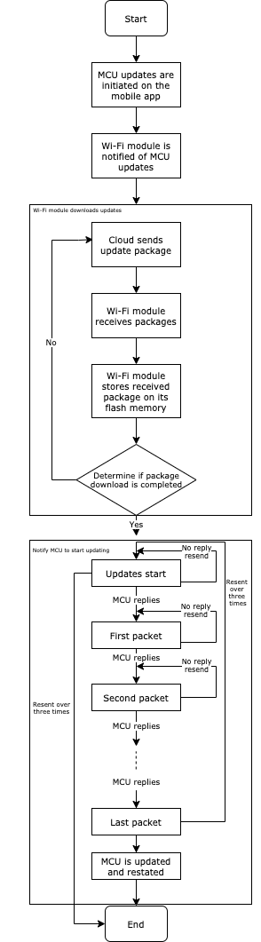
OTA updates without scratchpad
The Wi-Fi module acts as the scratchpad for the MCU firmware updates. It can store the update file of up to 1.5 MB (1572864 bytes). The Wi-Fi module will download and store the update file and when the download is completed, it notifies the MCU to start the update.
-
During the update process, do not power off or unplug the accessory. If any power failure occurs, the Wi-Fi module will keep trying until the update succeeds. The Wi-Fi module will check the update status each time it is started. If a failed update is detected, the module will initiate an update request from the command
0x0Auntil the update succeeds. -
For more information, see the OTA update flowchart.
- The MCU must this command each time after the module is started or restarted.
- The bootloader of the MCU must support
0x0Aand0x0Bcommands. - The OTA MCU firmware updates and Wi-Fi module firmware updates cannot be triggered at the same time. If OTA MCU firmware updates are triggered, the OTA Wi-Fi module firmware updates will be triggered after the MCU firmware is updated successfully, and vice versa.
Appendix 1: HomeKit accessory list
| Category | Value |
|---|---|
| Bridges | 2 |
| Fans | 3 |
| Garage Door Openers | 4 |
| Lighting | 5 |
| Locks | 6 |
| Outlets | 7 |
| Switches | 8 |
| Thermostats | 9 |
| Sensors | 10 |
| Security Systems | 11 |
| Doors | 12 |
| Windows | 13 |
| Window Coverings | 14 |
| Programmable Switches | 15 |
| Reserved | 16 |
| IP Cameras | 17 |
| Video Doorbells | 18 |
| Air Purifiers | 19 |
| Heaters | 20 |
| Air Conditioners | 21 |
| Humidifiers | 22 |
| Dehumidifiers | 23 |
| Sprinklers | 28 |
| Faucets | 29 |
| Shower Systems | 30 |
Appendix 2: HomeKit service list
| Service | Service string identifier |
|---|---|
| Accessory Information | "3E" |
| HAP Protocol Information | "A2" |
| Garage Door Opener | "41" |
| Light Bulb | "43" |
| Lock Management | "44" |
| Lock Mechanism | "45" |
| Switch | "49" |
| Outlet | "47" |
| Thermostat | "4A" |
| Air Quality Sensor | "8D" |
| Security System | "7E" |
| Carbon Monoxide Sensor | "7F" |
| Contact Sensor | "80" |
| Door | "81" |
| Humidity Sensor | "82" |
| Leak Sensor | "83" |
| Light Sensor | "84" |
| Motion Sensor | "85" |
| Occupancy Sensor | "86" |
| Smoke Sensor | "87" |
| Stateless Programmable Switch | "89" |
| Temperature Sensor | "8A" |
| Window | "8B" |
| Window Covering | "8C" |
| Battery Service | "96" |
| Carbon Dioxide Sensor | "97" |
| Fan | "B7" |
| Slat | "B9" |
| Filter Maintenance | "BA" |
| Air Purifier | "BB" |
| Heater Cooler | "BC" |
| Humidifier Dehumidifier | "BD" |
| Service Label | "CC" |
| Irrigation System | "CF" |
| Valve | "D0" |
| Faucet | "D7" |
Appendix 3: HomeKit characteristics
| Characteristic | String identifier | Description |
|---|---|---|
| Administrator Only Access | "1" | When this mode is enabled, the accessory only accepts administrator access. |
| Brightness | "8" | This characteristic describes a perceived level of brightness. |
| Cooling Threshold Temperature | "D" | This characteristic describes the cooling threshold in Celsius for accessories that support simultaneous heating and cooling. |
| Current Door State | "E" | This characteristic describes the current state of a door. |
| Current Heating Cooling State | "F" | This characteristic describes the current mode of an accessory that supports cooling or heating its environment. |
| Current Relative Humidity | "10" | This characteristic describes the current relative humidity of the accessory’s environment. |
| Current Temperature | "11" | This characteristic describes the current temperature of the environment. |
| Firmware Revision | "52" | This characteristic describes a firmware revision string. |
| Hardware Revision | "53" | This characteristic describes a hardware revision string. |
| Heating Threshold Temperature | "12" | This characteristic describes the heating threshold in Celsius for accessories that support simultaneous heating and cooling. |
| Hue | "13" | This characteristic describes hue or color. |
| Identify | "14" | This characteristic enables the accessory to run its identify routine. |
| Lock Control Point | "19" | The accessory accepts writes to this characteristic to perform vendor-specific actions. |
| Lock Current State | "1D" | The current state of the physical security mechanism. |
| Lock Last Known Action | "1C" | The last known action of the lock mechanism. |
| Lock Management Auto Security Timeout | "1A" | A value greater than 0 indicates if the lock mechanism enters the unsecured state, it will automatically attempt to enter the secured state after n seconds, where n is the value provided in the write. A value of 0 indicates this feature is disabled. |
| Lock Target State | "1E" | The target state of the physical security mechanism. |
| Logs | "1F" | Read from this characteristic to get timestamped logs from the accessory. |
| Manufacturer | "20" | This characteristic contains the name of the company whose brand will appear on the accessory. |
| Model | "21" | This characteristic contains the manufacturer-specific model of the accessory. |
| Motion Detected | "22" | This characteristic indicates if a motion was detected. |
| Name | "23" | This characteristic describes a name and must not be a null value. |
| Obstruction Detected | "24" | This characteristic describes the current state of an obstruction sensor. |
| On | "25" | This characteristic represents the states for on and off. |
| Outlet In Use | "26" | This characteristic describes if the power outlet has an appliance physically plugged in. |
| Rotation Direction | "28" | This characteristic describes the direction of rotation of a fan. |
| Rotation Speed | "29" | This characteristic describes the rotation speed of a fan. |
| Saturation | "2F" | This characteristic describes color saturation. |
| Serial Number | "30" | This characteristic contains the manufacturer-specific serial number of the accessory. The |
| length must be greater than 1. | ||
| Target Door State | "32" | This characteristic describes the target state of a door. |
| Target Heating Cooling State | "33" | This characteristic describes the target mode of an accessory that supports heating/cooling. |
| Target Relative Humidity | "34" | This characteristic describes the target relative humidity that the accessory is actively attempting to reach. |
| Target Temperature | "35" | This characteristic describes the target temperature in Celsius that the accessory is actively attempting to reach. |
| Temperature Display Units | "36" | This characteristic describes units of temperature used for presentation purposes. |
| Version | "37" | This characteristic contains a version string. |
| Air Particulate Density | "64" | This characteristic indicates the current air particulate matter density in micrograms/m3. |
| Air Particulate Size | "65" | This characteristic indicates the size of air particulate matter in micrometers. |
| Security System Current State | "66" | This characteristic describes the state of a security system. |
| Security System Target State | "67" | This characteristic describes the target state of the security system. |
| Battery Level | "68" | This characteristic describes the current level of the battery. |
| Carbon Dioxide Detected | "69" | This characteristic indicates if a sensor detects abnormal levels of Carbon Dioxide. |
| Contact Sensor State | "6A" | This characteristic describes the state of a door/window contact sensor. |
| Current Ambient Light Level | "6B" | This characteristic indicates the current light level. |
| Current Horizontal Tilt Angle | "6C" | This characteristic describes the current angle of horizontal slats for accessories such as windows, fans, and more. |
| Current Position | "6D" | This characteristic describes the current position of accessories. |
| Current Vertical Tilt Angle | "6E" | This characteristic describes the current angle of vertical slats for accessories such as windows, fans, and more. |
| Hold Position | "6F" | This characteristic causes the service such as door or window covering to stop at its current position. |
| Leak Detected | "70" | This characteristic indicates if a sensor detected a leak. |
| Occupancy Detected | "71" | This characteristic indicates if occupancy was detected. |
| Position State | "72" | This characteristic describes the state of the position of accessories. |
| Programmable Switch Event | "73" | This characteristic describes an event generated by a programmable switch. |
| Status Active | "75" | This characteristic describes an accessory’s current working status. |
| Smoke Detected | "76" | This characteristic indicates if a sensor detects abnormal levels of smoke. |
| Status Fault | "77" | This characteristic describes an accessory that has a fault. |
| Status Jammed | "78" | This characteristic describes an accessory that is in a jammed state. |
| Status Low Battery | "79" | This characteristic describes an accessory’s battery status. |
| Status Tampered | "7A" | This characteristic describes an accessory that has been tampered with. |
| Target Horizontal Tilt Angle | "7B" | This characteristic describes the target angle of horizontal slats for accessories such as windows, fans, and more. |
| Target Position | "7C" | This characteristic describes the target position of accessories. |
| Target Vertical Tilt Angle | "7D" | This characteristic describes the target angle of vertical slats for accessories such as windows, fans, and more. |
| Security System Alarm Type | "8E" | This characteristic describes the type of alarm triggered by a security system. |
| Charging State | "8F" | This characteristic describes the charging state of a battery or an accessory. |
| Carbon Monoxide Level | "90" | This characteristic indicates the Carbon Monoxide levels detected in parts per million (ppm). |
| Carbon Monoxide Peak Level | "91" | This characteristic indicates the highest detected level (ppm) of Carbon Monoxide detected by a sensor. |
| Carbon Dioxide Detected | "92" | This characteristic indicates if a sensor detects abnormal levels of Carbon Dioxide. |
| Carbon Dioxide Level | "93" | This characteristic indicates the detected level of Carbon Dioxide in parts per million (ppm). |
| Carbon Dioxide Peak Level | "94" | This characteristic indicates the highest detected level (ppm) of carbon dioxide detected by a sensor. |
| Air Quality | "95" | This characteristic describes the subject assessment of air quality by an accessory. |
| Accessory Flags | "A6" | When set indicates accessory requires additional setup. |
| Lock Physical Controls | "A7" | This characteristic describes a way to lock a set of physical controls on an accessory. |
| Current Air Purifier State | "A9" | This characteristic describes the current state of the air purifier. |
| Current Slat State | "AA" | This characteristic describes the current state of the slats. |
| Slat Type | "C0" | This characteristic describes the type of the slats. |
| Filter Life Level | "AB" | This characteristic describes the current filter life level. |
| Filter Change Indication | "AC" | This characteristic describes if a filter needs to be changed. |
| Reset Filter Indication | "AD" | This characteristic allows a user to reset the filter indication. |
| Target Air Purifier State | "A8" | This characteristic describes the target state of the air purifier. |
| Target Fan State | "BF" | This characteristic describes the target state of the fan. |
| Current Fan State | "AF" | This characteristic describes the current state of the fan. |
| Active | "B0" | The Active characteristic indicates whether the service is currently active. |
| Swing Mode | "B6" | This characteristic describes if swing mode is enabled. |
| Current Tilt Angle | "C1" | This characteristic describes the current angle of slats for accessories such as windows, fans, and more. |
| Target Tilt Angle | "C2" | This characteristic describes the target angle of slats for accessories such as windows, fans, and more. |
| Ozone Density | "C3" | This characteristic indicates the current ozone density in micrograms/m3. |
| Nitrogen Dioxide Density | "C4" | This characteristic indicates the current NO2 density in micrograms/m3. |
| Sulphur Dioxide Density | "C5" | This characteristic indicates the current SO2 density in micrograms/m3. |
| PM2.5 Density | "C6" | This characteristic indicates the current PM2.5 micrometer particulate density in micrograms/m3. |
| PM10 Density | "C7" | This characteristic indicates the current PM10 micrometer particulate density in micrograms/m3. |
| VOC Density | "C8" | This characteristic indicates the current volatile organic compound density in micrograms/m3. |
| Service Label Index | "CB" | This characteristic should be used to identify the index of the label that maps to Service Label Namespace used by the accessory. |
| Service Label Namespace | "CD" | This characteristic describes the naming schema for an accessory. |
| Color Temperature | "CE" | This characteristic describes color temperature. |
| Current Heater Cooler State | "B1" | This characteristic describes the current state of a heater cooler. |
| Target Heater Cooler State | "B2" | This characteristic describes the target state of a heater cooler. |
| Current Humidifier Dehumidifier State | "B3" | This characteristic describes the current state of a humidifier or/and a dehumidifier. |
| Target Humidifier Dehumidifier State | "B4" | This characteristic describes the target state of a humidifier or/and a dehumidifier. |
| Water Level | "B5" | This characteristic describes the current water level. |
| Relative Humidity Dehumidifier Threshold | "C9" | This characteristic describes the relative humidity dehumidifier threshold. |
| Relative Humidity Humidifier Threshold | "CA" | This characteristic describes the relative humidity humidifier threshold. |
| Program Mode | "D1" | This characteristic describes if there are programs scheduled on the accessory. |
| In Use | "D2" | This characteristic describes if the service is in use. |
| Set Duration | "D3" | This characteristic describes the set duration. |
| Remaining Duration | "D4" | This characteristic describes the remaining duration on the accessory. |
| Valve Type | "D5" | This characteristic describes the type of valve. |
| Is Configured | "D6" | This characteristic describes if the service is configured for use. |
| Product Data | "220" | This characteristic describes product data. |
Appendix 4: Module information
| Name | Description | Options | Read | Write |
|---|---|---|---|---|
| cc | Country code | 0: applies to China, Korea, Singapore, Australia, Japan (1-13), and others 1: applies to the United States, Taiwan (China), and Canada 2: applies to Japan (1-14) 3: applies to Europe |
Supported | Not supported |
Appendix 5: OTA updates without scratchpad
Change history
| Description | Date | Note |
|---|---|---|
| Create | September 15, 2020 | The first release. |
| Amendment | November 18, 2020 | Added the command to read the country code from the Wi-Fi module. |
| Amendment | December 21, 2020 | 1. Added three categories including sprinklers, faucets, and shower systems. 2. Modified the description of service configuration. |
| Amendment | January 7, 2021 | 1. Added the command to notify the module of the new feature configuration. 2. Added support for single backup of OTA MCU firmware updates. |
| Amendment | February 4, 2021 | 1. Added the prompt of HomeKit compatibility. 2. Added the command to configure the valid values of HomeKit characteristics. |
| Amendment | April 15, 2021 | Added the command to read the serial number of the Wi-Fi module. |
Is this page helpful?
YesFeedbackIs this page helpful?
YesFeedback


