TYWE5P Module Datasheet
Product Overview
After a period of service, this module will become deprecated due to product upgrades and iterations, user requirements, production inventory, or other reasons. To improve the compatibility of your smart devices and minimize the impact on your use, Tuya continues to provide webpage documentation of deprecated modules, but no longer maintains or updates the documentation. The content herein is for reference only.
If you have any questions, submit a ticket to contact Tuya or consult Tuya’s account manager to request support.
TYWE5P is a low-power built-in Wi-Fi module developed by Hangzhou Tuya Information Technology Co., Ltd. It consists of a highly integrated radio frequency chip (ESP8266) and several peripheral components, with a built-in Wi-Fi network protocol stack and robust library functions. TYWE5P is embedded with a low-power 32-bit CPU, 1 MB flash, 50 KB SRAM, and robust peripheral resources.
TYWE5P is an RTOS platform that integrates all the function libraries of the Wi-Fi MAC and TCP/IP protocols. You can develop built-in Wi-Fi products as required.
Figure 1 shows the schematic diagram of TYWE5P. 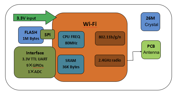
Figure 1 TYWE5P schematic diagram
Features
-
Built-in low power-consuming 32-bit CPU functioning as an application processor
Basic frequency: 80 MHz and 160 MHz
-
Working voltage: 3.0 V to 3.6 V
-
Peripherals: nine GPIOs and one UART
-
Wi-Fi connectivity
-
802.11 b/g/n
-
Channels 1 to 14@2.4 GHz
-
WPA/WPA2 security mode
-
Up to +20 dBm output power in 802.11b mode
-
STA/AP/STA+AP working mode
-
SmartConfig and AP network configuration modes(for Android and iOS devices)
-
-
Onboard PCB antenna
-
Working temperature: –20°C to +125°C
Major Application Fields
- Intelligent building
- Intelligent home and household appliances
- Intelligent socket and smart lighting
- Industrial wireless control
- Baby monitor
- Network camera
- Intelligent bus
Module Interfaces
Dimensions and Pin Layout
TYWE5P provides two rows of pins with a distance of 2 mm between every two pins.
TYWE5P dimensions: 16 mm (W) x 24.74 mm (L) x 3.5 mm (H). Figure 2 shows the overall pin layout of TYWE5P.
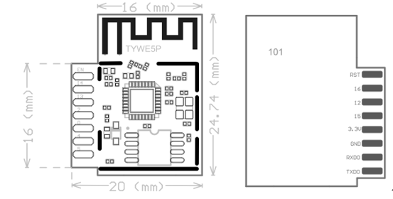
Figure 2 Front and back views of TYWE5P
Pin Definition
Table 1 describes the interface pins.
Table 1 TYWE5P interface pins
| No. | Symbol | I/O Type | Function |
|---|---|---|---|
| 1 | TXD0 | O | UART0_TXD (1) |
| 2 | GPIO5 | I/O | GPIO_05 |
| 3 | RXD0 | I/O | UART0_RXD (1) |
| 4 | GPIO4 | I/O | GPIO_04 |
| 5 | GND | P | Power supply reference ground pin |
| 6 | GPIO0 | I/O | GPIO_0 (Used during module power-on and initialization. Use it with caution.) |
| 7 | VCC | P | Power supply pin of the module (3.3 V) |
| 8 | GPIO2 | O | UART0_TXD (used for printing the internal information of the module) |
| 9 | GPIO15 | O | GPIO_15 (Used during module power-on and initialization. Use it with caution.) |
| 10 | GPIO13 | I/O | GPIO_13 |
| 11 | GPIO12 | I/O | GPIO_12 |
| 12 | GPIO14 | I/O | GPIO_14 |
| 13 | GPIO16 | I/O | GPIO_16 (Connect it to a 10 KΩ pull-up resistor.) |
| 14 | EN | I | Module enablement pin. Connect it to 3.3 V power supply. (The module has been connected to a pull-up resistor.) |
| 15 | RST | I/O | Hardware reset pin (It is valid at low level and has been connected to a pull-up resistor.) |
Note:
- P indicates power-supply pins, I/O indicates input/output pins, and AI indicates analog input pins.
- RST is only a hardware reset pin of the module, which cannot clear the Wi-Fi network configuration.
- UART0 is a user serial port. When the module is powered on and started, data is exported from the serial port, which can be ignored.
Electrical Parameters
Absolute Electrical Parameters
Table 3 Absolute electrical parameters
| Parameter | Description | Minimum Value | Maximum Value | Unit |
|---|---|---|---|---|
| Ts | Storage temperature | –20 | 85 | °C |
| VIN | Power supply voltage | –0.3 | 3.6 | V |
| Static electricity voltage (human model) | TAMB – 25°C | - | 2 | kV |
| Static electricity voltage (machine model) | TAMB – 25°C | - | 0.5 | kV |
Electrical Conditions
Table 4 Normal electrical conditions
| Parameter | Description | Minimum Value | Typical Value | Maximum Value | Unit |
|---|---|---|---|---|---|
| Ta | Working temperature | –20 | - | 125 | °C |
| VCC | Working voltage | 3.0 | 3.3 | 3.6 | V |
| VIL | I/O low-level input | –0.3 | - | VCC x 0.25 | V |
| VIH | I/O high-level input | VCC x 0.75 | - | VCC | V |
| VOL | I/O low-level output | - | - | VCC x 0.1 | V |
| VoH | I/O high-level output | VCC x 0.8 | - | VCC | V |
| Imax | I/O drive current | - | - | 12 | mA |
Wi-Fi TX Power Consumption
Table 5 TX power consumption during constant emission
| Symbol | Mode | Rate | TX Power | Typical Value | Unit |
|---|---|---|---|---|---|
| IRF | 11b | 11 Mbit/s | +17 dBm | 220 | mA |
| IRF | 11g | 54 Mbit/s | +15 dBm | 110 | mA |
| IRF | 11n | MCS7 | +13 dBm | 100 | mA |
Wi-Fi RX Power Consumption
Table 6 RX power consumption during constant receiving
| Symbol | Mode | Rate | Typical Value | Unit |
|---|---|---|---|---|
| IRF | 11b | 11 Mbit/s | 70 | mA |
| IRF | 11g | 54 Mbit/s | 70 | mA |
| IRF | 11n | MCS7 | 70 | mA |
Power Consumption in Working Mode
Table 7 TYWE5P working current
| Working Mode | Working Status (Ta = 25°C) | Average Value | Maximum Value | Unit |
|---|---|---|---|---|
| EZ mode | The module is in the EZ state and the Wi-Fi indicator fast flashes. | 80 | 151 | mA |
| AP mode | The module is in the AP state and the Wi-Fi indicator slowly flashes. | 90 | 451 | mA |
| Connection mode | The module is in the connected state and the Wi-Fi indicator is steady on. | 58.5 | 411 | mA |
| Disconnection mode | The module is in the disconnected state and the Wi-Fi indicator is steady off. | 80 | 430 | mA |
RF Features
Basic RF Features
Table 8 Basic RF features
| Parameter | Description |
|---|---|
| Frequency band | 2.412 GHz to 2.484 GHz |
| Wi-Fi standard | IEEE 802.11 b/g/n (channels 1 to 14) |
| Data transmission rate | 11b: 1, 2, 5.5, 11 (Mbit/s) 11g: 6, 9, 12, 18, 24, 36, 48, 54 (Mbit/s) 11n: HT20 MCS0 to MCS7 |
| Antenna type | PCB antenna |
Wi-Fi Output Performance
Table 9 TX power during constant emission
| Parameter | Minimum Value | Typical Value | Maximum Value | Unit | |
|---|---|---|---|---|---|
| RF average output power, 802.11b CCK mode | 1 Mbit/s | - | 20 | - | dBm |
| RF average output power, 802.11g OFDM mode | 54 Mbit/s | - | 17 | - | dBm |
| RF average output power, 802.11n OFDM mode | MCS7 | - | 14 | - | dBm |
| Frequency error | –10 | - | 10 | ppm |
Wi-Fi RX Sensitivity
Table 10 RX sensitivity
| Parameter | Minimum Value | Typical Value | Maximum Value | Unit | |
|---|---|---|---|---|---|
| PER < 8%, RX sensitivity, 802.11b CCK mode | 1 Mbit/s | - | –91 | - | dBm |
| PER < 10%, RX sensitivity, 802.11g OFDM mode | 54 Mbit/s | - | –75 | - | dBm |
| PER < 10%, RX sensitivity, 802.11n OFDM mode | MCS7 | - | –72 | - | dBm |
Antenna Information
Antenna Types
Only the onboard PCB antenna is used.
Antenna Interference Reduction
When using an onboard PCB antenna on a Wi-Fi module, make sure that the antenna on the module is at least 15 mm away from other metal parts to ensure optimal wireless performance.
To prevent a negative effect on antenna performance, do not route copper or cable wires along the antenna area of the user PCB board.
For details about the area of the onboard PCB antenna on a module, see Figure 3.
Production Instructions
Mechanical Dimensions
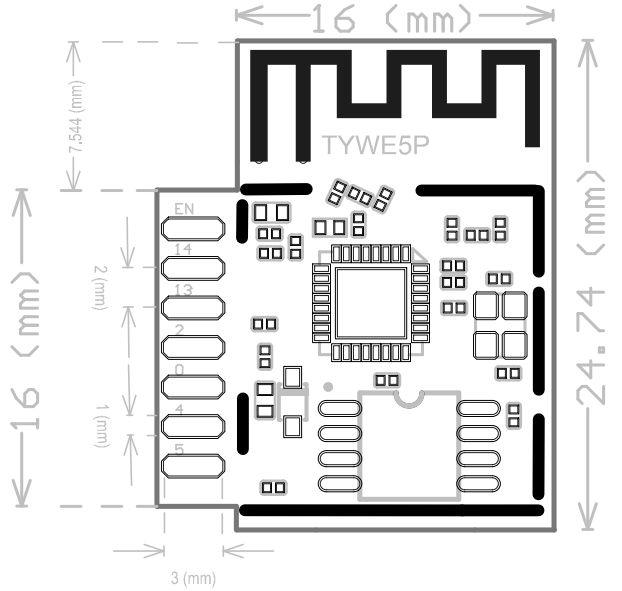
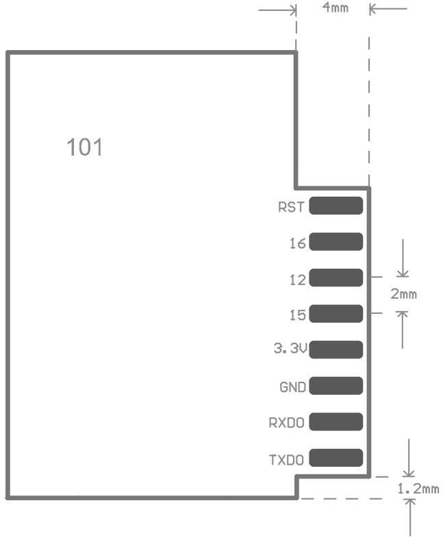
Figure 3 Mechanical dimensions of TYWE5P
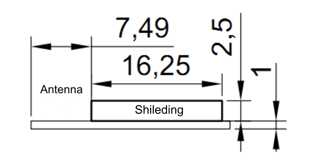
Figure 4 TYWE5P side view
Recommended PCB Encapsulation
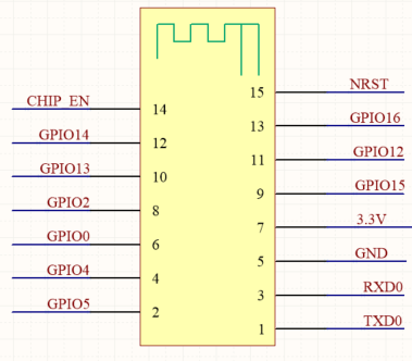
Figure 5 TYWE5P schematic diagram and pin connection
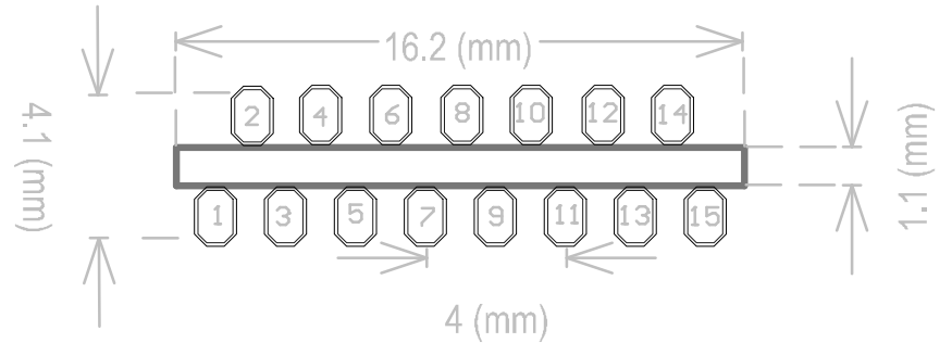
Figure 6 PCB encapsulation diagram of TYWE5P
Production Instructions
Storage conditions of a delivered module are as follows:
- The anti-moisture bag must be placed in an environment where the temperature is under 30°C and the relative humidity is under 85%.
- The shelf life of a dry-packaged product is six months from the date when the product is packaged and sealed.
Note:
- Throughout the production process, each involved operator must wear an electrostatic ring.
- During the operation, strictly protect the module from water and strains.
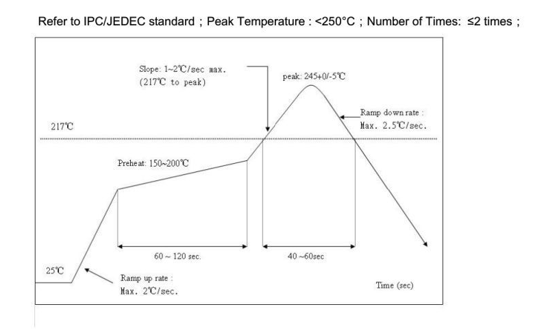
Recommended Oven Temperature Profile
Is this page helpful?
YesFeedbackIs this page helpful?
YesFeedback


