Wi-Fi module introduction--TYJW2.1
Product Overview
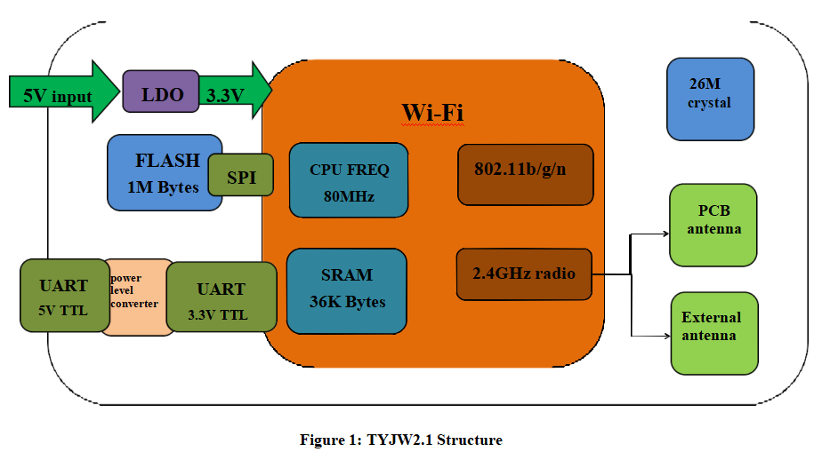
TYJW2.1 is a Wi-Fi module, developed by Hangzhou Tuya Information Technology Co., Ltd., for serial port communication at the level of 5V TTL. It mainly consists of a highly integrated wireless RF chip ESP8266EX and external flash chip, with the built-in Wi-Fi network protocol stack and rich library functions. TYJW2.1 also contains a 32-bit CPU of low power consumption, 1Mbyte flash and 36K SRAM.
TYJW2.1 is also an RTOS platform integrating all Wi-Fi MACs and TCP/IP protocol libraries. The user can develop embedded Wi-Fi products that meet their needs, based on serial communication.
The structure of TYJW2.1 is shown in Figure 1:
1.1 Features
- Built-in 32-bit CPU of low power consumption, also used as an application processor.
Main frequency: 80MHz and 160MHz
- Operating voltage: 4.5V-5.5V
- Peripheral: 1×UART (level: 5V TTL)
- Wi-Fi connectivity
802.11 b/g/n
Channel 1-14@2.4GHz
Support the WPA/WPA2 security mode.
Output power: maximum +20dBm in the 802.11b mode.
Support the STA/AP/STA+AP mode.
Support the SmartConfig function (including Android and IOS devices).
IPEX connector between the onboard PCB antenna and external antenna.
Operating temperature: -20℃ to 85℃
1.2 Main Applications
- Smart buildings
- Smart home/household appliances
- Healthcare
- Industrial wireless control
- Handheld devices
Module Interface
Size and Package
Electrical interface of TYJW2.1: PH-4AW connector, with the pin spacing of 2.0mm.
Size of TYJW2.1: 49.6 mm (W)×31 mm (L) ×9.1 mm (H). Refer to Figure 2 for its package.
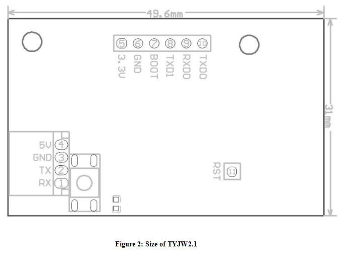
Pin Definitions
The interface pins are defined in Table 1.
Table 1: Layout of TYJW2.1 Interface Pins
| Pin | Symbol | IO Type | Function |
|---|---|---|---|
| 1 | RX | I/O | RX communication port of the module, with the input level of 5V TTL |
| 2 | TX | I/O | TX communication port of the module, with the input level of 5V TTL |
| 3 | GND | P | Reference ground pin of the power supply of module |
| 4 | VCC | P | Input pin of the 5V power supply of module |
Note: P is the power pin, and I/O is the input/output pin.
Test Pin Definitions
Test pins are defined in Table 2.
Table 2: Layout of TYJW2.1 Test Pins
| Pin | Symbol | IO Type | Function |
|---|---|---|---|
| 5 | 3.3V | P | Pin of the internal 3.3V power supply of module |
| 6 | GND | P | Referent ground pin of the power supply of module |
| 7 | BOOT | I/O | IO0 pin, for module firmware programming |
| 8 | TXD1 | I/O | Module information printing port |
| 9 | RXD0 | I/O | Module firmware programming port |
| 10 | TXD0 | I/O | Module firmware programming port |
| 11 | RST | I/O | Module hardware resetting pin |
Notes: P is the power pin, and I/O is the input/output pin.
When the IO0 is null, the module runs normally; and when IO0 is at the low level, the module is in the status of firmware programming.
RST is used for module hardware resetting only, but not for clearing Wi-Fi network information.
Test pins are not recommended.
Electrical Parameters
Absolute Electrical Parameters
Table 3: Absolute Parameters
| Parameter | Description | Min. | Max. | Unit |
|---|---|---|---|---|
| Ts | Storage temperature | -20 | 85 | ℃ |
| VCC | Power supply voltage | -0.3 | 5.5 | V |
| Electrostatic discharge voltage (human body model) | TAMB-25℃ | - | 2 | KV |
| Electrostatic discharge voltage (machine model) | TAMB-25℃ | - | 0.5 | KV |
Operating Conditions
Table 4: Normal Operating Conditions
| Parameter | Description | Min. | Typical | Max. | Unit |
|---|---|---|---|---|---|
| Ta | Ambient temperature | -20 | - | 85 | ℃ |
| VCC | Operating voltage | 4.5 | 5 | 5.5 | V |
| VIL | IO low-level input | -0.3 | - | VCC*0.25 | V |
| VIH | IO high-level input | VCC*0.75 | - | VCC | V |
| VOL | IO low-level output | - | - | VCC*0.1 | V |
| VoH | IO high-level output | VCC*0.8 | - | VCC | V |
| Imax | IO drive current | - | - | 5 | mA |
Power Consumption for Wi-Fi Transmission
Table 5: Power Consumption of Continuous TX Transmission
| Symbol | Mode | Rate | Typical | Unit |
|---|---|---|---|---|
| IRF | 11b | 11Mbps | 260 | mA |
| IRF | 11g | 54Mbps | 100 | mA |
| IRF | 11n | MCS7 | 100 | mA |
Power Consumption for Wi-Fi Reception
Table 6: Power Consumption of Continuous RX Reception
| Symbol | Mode | Rate | Typical | Unit |
|---|---|---|---|---|
| IRF | 11b | 11Mbps | 70 | mA |
| IRF | 11g | 54Mbps | 70 | mA |
| IRF | 11n | MCS7 | 70 | mA |
Power Consumption in Operating Mode
Table 7: Operating Current of TYJW2.1
| Operating Mode | **Operating Status (**Ta=25℃) | Average | Maximum | Unit |
|---|---|---|---|---|
| Fast connection networking status | The module is in the status of fast connection networking, with the Wi-Fi indicator flickering fast. | 90 | 151 | mA |
| Hotspot networking status | The module is in the status of hotspot networking, with the Wi-Fi indicator flickering slowly. | 101 | 451 | mA |
| Network connection status | The module is connected with the Internet, with the Wi-Fi indicator normally ON. | 58.5 | 411 | mA |
| Network disconnection status | The module is disconnected from the Internet, with the Wi-Fi indicator normally OFF. | 156 | 430 | mA |
RF Characteristics
Basic RF Characteristics
Table 8: Basic RF Characteristics
| Parameter | Detailed Description |
|---|---|
| Operating frequency | 2.400-2.500GHz |
| Wi-Fi standard | IEEE 802.11b/g/n (Channel 1-14) |
| Data transmission rate | 11b:1,2,5.5, 11 (Mbps)11g:6,9,12,18,24,36,48,54(Mbps)11n:HT20 MCS0~7 |
| Antenna type | PCB antenna (default)U.FL RF connector: external antenna (optional) |
Wi-Fi Output Power
Table 9: Continuous Transmitting Power of TX
| Parameters | Min. | Typical | Max. | Unit | |
|---|---|---|---|---|---|
| RF average output power, 802.11b CCK Mode | 1M | - | 20 | - | dBm |
| RF average output power, 802.11g OFDM Mode | 54M | - | 17 | - | dBm |
| RF average output power, 802.11n OFDM Mode | MCS7 | - | 14 | - | dBm |
| Frequency error | -10 | - | 10 | ppm |
Wi-Fi Receiving Sensitivity
Table 10: RX Sensitivity
| Parameter | Min. | Typical | Max. | Unit | |
|---|---|---|---|---|---|
| RX sensitivity at PER<8%, 802.11b CCK Mode | 1M | - | -91 | - | dBm |
| RX sensitivity at PER<10%, 802.11g OFDM Mode | 54M | - | -75 | - | dBm |
| RX sensitivity at PER<10%, 802.11n OFDM Mode | MCS7 | - | -72 | - | dBm |
Antenna Information
Antenna Type
Two kinds of antenna are applicable: PCB board antenna and external antenna, the former of which is applied in the default mode. For the use of the external antenna, contact our sales staff.
Reduction of Antenna Interference
When the PCB board antenna is used in the Wi-Fi module, it is recommended to keep the module antenna at least 15mm away from other metal parts, in order to optimize the Wi-Fi performance.
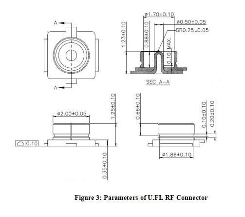
U.FL RF Connector
The parameters of the U.FL RF connector are shown below.
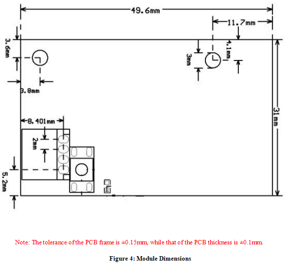
Packaging Information and Production Guide
Mechanical Dimensions
Production Guide
Module storage conditions:
- The moisture-proof bag must be stored in the environment with the temperature below 30℃ and the relative humidity less than 85%.
- The warranty period of the product in the dry package should be six months from the date of packaging.
Notes:
- All operators must wear the electrostatic ring during production.
- The module must be prevented from water or dirt during operation.
Is this page helpful?
YesFeedbackIs this page helpful?
YesFeedback


