Wi-Fi module introduction--TYLC2
Product Overview
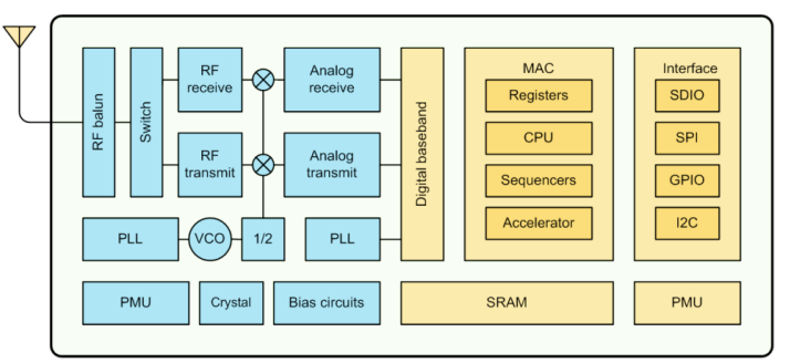
TYLC2 is a low-power, embedded Wi-Fi module developed by Hangzhou Tuya Information Technology Co., Ltd. specifically designed for use in smart lighting applications. The module consists of the highly integrated Wi-Fi SoC ESP8266EX, an external flash memory, and a DC/DC regulator circuit. It comes with a built-in Wi-Fi network protocol, and a large number of library functions. TYLC2 also contains a low-power 32-bit CPU, 1Mbyte flash, 36K SRAM, and a large variety of peripheral resources.
TYLC2 is an RTOS platform that gathers all Wi-Fi MAC and TCP/IP libraries into one place. It enables users to build on the product and develop embedded Wi-Fi products that suit their individual needs.
The ESP8266 diagram is as shown in Figure 1:
Figure1 ESP8266 Diagram
Features
- Built-in low-power 32-bit CPU that doubles as an application processor
Supports CPU frequencies of 80MHz and 160MHz
- Operating voltage: 5-38V (31-38v by default)
- Peripherals: 4×GPIOs (including 2×I2Cs)
- Wi-Fi connectivity
802.11 b/g/n
Channels 1-14@2.4GHz
Supports WPA/WPA2
+20dBm output in 802.11b mode
Supports STA/AP/STA+AP modes
Supports SmartConfig (for both Android and IOS devices)
Operating temperature: -20℃ to 70℃ (commercial); -40℃ to 85℃ (industrial)
Primary fields of application
-
Industrial wireless control
-
Smart lighting
Module Interfaces
Package dimensions
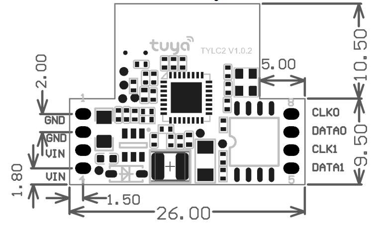
TYLC2 has 2 rows of pins (2×4) with 2.0mm pitch.
TYLC2 dimensions: 26 mm (W) × 20 mm (L) × 3.5 mm (H); package as shown in Figure 2:
Figure2 TYLC2 Dimensional Drawing
Pin definition
Conventional pins are defined as shown in Table 1:
Table 1 TYLC2 Pinout
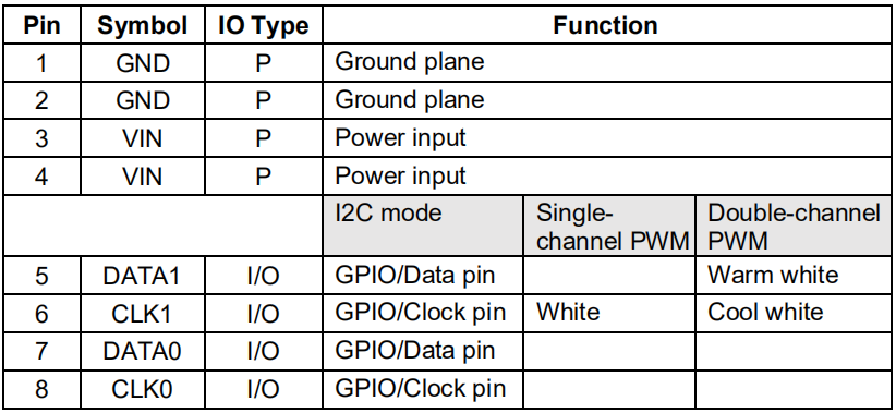
Notes: P indicates the power pin; I/O indicates the input/output pin
Electrical Parameters
Absolute electrical parameters
Table 2 Absolute Parameters
| Parameters | Description | Min | Max | Unit |
|---|---|---|---|---|
| Ts | Storage temperature | -40 | 85 | ℃ |
| VIN | Input voltage | -0.3 | 40 | V |
| Electrostatic discharge voltage (human-body model) | TAMB-25℃ | - | 2 | KV |
| Electrostatic discharge voltage (machine model) | TAMB-25℃ | - | 0.5 | KV |
Operating conditions
Table 3 Normal operating conditions
| Parameters | Description | Min | Typ | Max | Unit |
|---|---|---|---|---|---|
| Ta | WorkingTemp(Commercial) | -20 | - | 70 | ℃ |
| Ta | WorkingTemp(Industrial) | -40 | 85 | ℃ | |
| VIN | Operating voltage | 5* | - | 38 | V |
| VIL | IO low input | -0.3 | - | 0.8 | V |
| VIH | IO high input | 2.47 | - | 3.6 | V |
| VOL | IO low output | - | - | 0.34 | V |
| VOH | IO high output | 2.64 | - | 3.4 | V |
| Imax | IO drive current | - | - | 12 | mA |
| Cpad | Input pin capacitance | - | 2 | pF |
*:The minimum factory default operating voltage is set to 31V.
Please specify a different value in the order if otherwise necessary
Wi-Fi TX power consumption
Table 4 TX continuous power @3.3V
| Symbol | Mode | Rate | Typ | Unit |
|---|---|---|---|---|
| IRF | 11b | 11Mbps | 260 | mA |
| IRF | 11g | 54Mbps | 100 | mA |
| IRF | 11n | MCS7 | 100 | mA |
Wi-Fi RX power consumption
Table 5 RX continuous power @3.3V
| Symbol | Mode | Rate | Typ | Unit |
|---|---|---|---|---|
| IRF | 11b | 11Mbps | 70 | mA |
| IRF | 11g | 54Mbps | 70 | mA |
| IRF | 11n | MCS7 | 70 | mA |
Power consumption in operating mode
Table 6 Operating current @3.3V
| Operation Mode | Operating condition, TA=25℃ | Typ | Peak* | Unit |
|---|---|---|---|---|
| Quick configuration | Fast blinking light during quick configuration | 100 | 151 | mA |
| Hotspot configuration | Slow blinking light during hotspot configuration | 105 | 451 | mA |
| Network connection idle | Connected to a network | 58.5 | 411 | mA |
| Network connection active | Connected to a network | 100 | 411 | mA |
| Disconnected | Not connected to any network | 156 | 430 | mA |
Notes: The peak period is Approx. 5us.
The abovementioned parameters are the measurement results for DC/DC output voltage 3.3 V. The DC/DC converter has an efficiency of Approx. 90%.
The parameters above may vary according to firmware.
RF Characteristics
Basic RF characteristics
Table 7 Basic RF characteristics
| Parameter | Description |
|---|---|
| Operating frequency | 2.400~2.500GHz |
| Wi-Fi standard | IEEE 802.11b/g/n (Channels 1-14) |
| Data transfer rate | 11b:1,2,5.5, 11 (Mbps) 11g:6,9,12,18,24,36,48,54(Mbps) 11n:HT20 MCS0~7 |
| Antenna type | PCB onboard antenna |
Wi-Fi output power
Table 8 TX Continuous Power During Transmission
| Parameter | Min | Typ | Max | Unit | |
|---|---|---|---|---|---|
| RF average output power, 802.11b CCK Mode | 11M | - | 17 | - | dBm |
| RF average output power, 802.11g OFDM Mode | 54M | - | 15 | - | dBm |
| RF average output power, 802.11n OFDM Mode | MCS7 | - | 13 | - | dBm |
| Frequency error | -20 | - | 20 | ppm |
Wi-Fi RX sensitivity
Table 9 RX Sensitivity
| Parameter | Min | Typ | Max | Unit | |
|---|---|---|---|---|---|
| PER<8%, RX sensitivity, 802.11b CCK Mode | 11M | - | -91 | - | dBm |
| PER<10%, RX sensitivity, 802.11g OFDM Mode | 54M | - | -75 | - | dBm |
| PER<10%, RX sensitivity, 802.11n OFDM Mode | MCS7 | - | -72 | - | dBm |
Antenna Signal
Antenna interference reduction
To optimize Wi-Fi performance of the Wi-Fi module in combination with the PCB onboard antenna, it is recommended to keep the antenna at least 15mm away from other metal components.
Manufacturing Work Instructions
Manufacturing work instructions
The storage conditions for the module after it is shipped are as follows:
- The moisture resistant bag must be stored at a temperature below 30℃, and under a relative humidity below 85%.
- The shelf life of dry, packed products is six months following the package date.
Important information
- All line workers must wear antistatic wrist straps throughout the entire production process.
- It is strictly prohibited to allow a module to come into contact with water or other contaminants during operations.
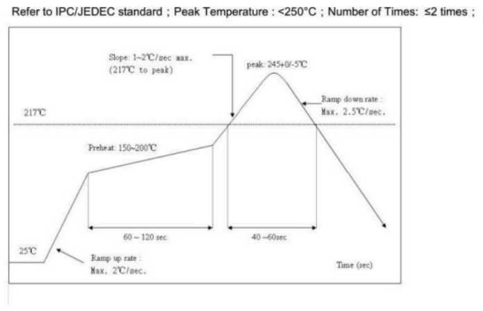
Recommended furnace temperature curve
Is this page helpful?
YesFeedbackIs this page helpful?
YesFeedback


