Wi-Fi module introduction--TYLC2V
Product Overview
TYLC2V is a low power consumption module with built-in Wi-Fi connectivity solution designed by HangZhou Tuya Technology Corporation. The Wi-Fi Module consists of a highly integrated wireless radio chip ESP8266 and some extra component that has been programed with Wi-Fi network protocol and plenty of software examples. TYLC2V include a 32-bit CPU, 1M byte flash, 50k SRAM and various peripheral resources.
TYLC2V is a RTOS platform, embedded with all the Wi-Fi MAC and TCP/IP protocol function examples, users can customize their Wi-Fi product by using these software examples.
Figure 1 shows the block diagram of the TYLC2V.
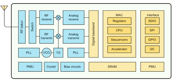
Figure 1 The block diagram of the TYLC2V
Features
- Integrated low power consumption 32-bit CPU, also known as application processor
-
Basic frequency of the CPU can support both 80MHz and 160MHz
-
Supply voltage range: 16V to 38V
- Peripherals: 4 GPIO channels
- Wi-Fi connectivity
802.11 b/g/n
channel 1 to 11@2.4Gfor FCC,channel 1 to 14 @2.4G for EU and Japan
Support WPA/WPA2
+20dBm output power in 802.11b mode
Support STA/AP/STA+AP operation mode
Support SmartConfig function for both Android and IOS devices
On-board PCB antenna
Operating temperature range: -20℃ to 105℃
Primary fields of application
- Intelligent Building
- Intelligent home, Intelligent household applications
- Health care
- Industrial wireless control
Dimensions and Footprint
Dimensions
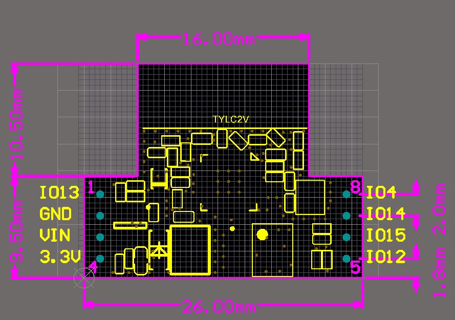
TYLC2V has 2 columns of Pins. The distance between each Pin is 2mm. Size of TYLC2V: 26mm(W)*20mm(L)*3.5mm(H)
Figure 2 shows the dimensions of TYLC2V.
Figure2 TYLC2V Dimensional Drawing
Pin definition
Table 1 shows the general pin attributes of TYLC2V
Table 1 The typical pin definition of TYLC2V
| PIN NO. | NAME | TYPE | DISCREPTION |
|---|---|---|---|
| 1 | IO13 | I/O | GPIO |
| 2 | GND | P | Ground |
| 3 | VIN | P | Supply voltage |
| 4 | 3.3V | P | Supply voltage OUTPUT |
| 5 | IO12 | I/O | GPIO |
| 6 | IO5 | I/O | GPIO |
| 7 | IO14 | I/O | GPIO |
| 8 | IO4 | I/O | GPIO |
Note: P: Power supply pins; I/O: Digital input or output pins;
Electrical Characteristics
Absolute Maximum Ratings
Table 2 Absolute Maximum Ratings
| PARAMETERS | DESCRIPTION | MIN | MAX | UNIT |
|---|---|---|---|---|
| Ts | Storage temperature | -20 | 105 | ℃ |
| VCC | Supply voltage | -0.3 | 40 | V |
| Static electricity voltage (human model) | TAMB-25℃ | - | 2 | KV |
| Static electricity voltage (machine model) | TAMB-25℃ | - | 0.5 | KV |
Electrical Conditions
Table 3 Electrical Conditions
| PARAMETERS | DESCRIPTION | MIN | TYPICAL | MAX | UNIT |
|---|---|---|---|---|---|
| Ta | Working temperature | -20 | - | 105 | ℃ |
| VCC | Working voltage | 16 | 38 | V | |
| VIL | IO low level input | -0.3 | - | 0.8 | V |
| VIH | IO high level input | 2.47 | - | 3.6 | V |
| VOL | IO low level output | - | - | 0.34 | V |
| VoH | IO high level output | 2.64 | - | 3.4 | V |
| Imax | IO drive current | - | - | 12 | mA |
Wi-Fi Transmitting Current Consumptions
Table 4 Wi-Fi RX current consumption @3.3V
| PARAMETERS | MODE | RATE | transmitting power | TYPICAL | UNIT |
|---|---|---|---|---|---|
| IRF | 11b | 11Mbps | +17dBm | 260 | mA |
| IRF | 11g | 54Mbps | +15dBm | 100 | mA |
| IRF | 11n | MCS7 | +13dBm | 100 | mA |
Wi-Fi Receiving Current Consumptions
Table 5 Wi-Fi RX current consumption @3.3V
| PARAMETERS | MODE | RATE | TYPICAL | UNIT |
|---|---|---|---|---|
| IRF | 11b | 11Mbps | 70 | mA |
| IRF | 11g | 54Mbps | 70 | mA |
| IRF | 11n | MCS7 | 70 | mA |
Working Mode Current Consumptions
Table 6 The module working current consumption @3.3V
| WORK MODE | AT TA=25℃ | TYPICAL | MAX* | UNIT |
|---|---|---|---|---|
| EZ Mode | TYLC2V is under EZ paring mode, Wi-Fi indicator light flashes quickly | 80 | 151 | mA |
| AP Mode | TYLC2V is under AP paring mode, Wi-Fi indicator light flashes slowly | 90 | 451 | mA |
| Operation Mode | TYLC2V is connected, Wi-Fi indicator light is on | 58.5 | 411 | mA |
| Disconnection Mode | TYLC2V is disconnected, Wi-Fi indicator light is off | 80 | 430 | mA |
WLAN Radio Specification
Basic Radio Frequency Characteristics
Table 7 Basic Radio frequency characteristics
| PARAMETERS | DESCRIPTION |
|---|---|
| Frequency band | 2.412GHz to 2.484GHz |
| Wi-Fi standard | IEEE 802.11b/g/n (Channels 1-14) |
| Data transfer rate | 11b:1,2,5.5, 11 (Mbps) 11g:6,9,12,18,24,36,48,54(Mbps) 11n:HT20 MCS0~7 |
| Antenna type | On-board PCB Antenna |
Wi-Fi Transmitting Power
Table 8 Wi-Fi transmitting power
| PARAMETERS | Min | Typ | Max | Unit | |
|---|---|---|---|---|---|
| RF average output power, 802.11b CCK Mode | 11M | - | 17 | - | dBm |
| RF average output power, 802.11g OFDM Mode | 54M | - | 15 | - | dBm |
| RF average output power, 802.11n OFDM Mode | MCS7 | - | 13 | - | dBm |
| The Frequency error | -20 | - | 20 | ppm |
Wi-Fi Receiving Sensitivity
Table 9 Wi-Fi Receiving sensitivity
| Parameter | Min | Typ | Max | Unit | |
|---|---|---|---|---|---|
| PER<8%, RX sensitivity, 802.11b CCK Mode | 11M | - | -91 | - | dBm |
| PER<10%, RX sensitivity, 802.11g OFDM Mode | 54M | - | -75 | - | dBm |
| PER<10%, RX sensitivity, 802.11n OFDM Mode | MCS7 | - | -72 | - | dBm |
5.Antenna Signal
Antenna Type
Antenna can be connected only using On-board PCB antenna.
Reduce Antenna Interference
While using the On-board PCB antenna, in order to have the best Wi-Fi performance, it’s recommended to keep a minimum 15mm distance between the antenna part and the other metal pieces.
User’s own PCBA design is recommended NOT to pass any wire, NOT do copper pour under the region of the module’s antenna, to avoid interferences.
Production Guide
Production Guide
The storage for the delivered module should meet the following condition:
- The anti-moisture bag should be kept in the environment with temperature < 30℃ and humidity < 85% RH.
- The expiration date is 6 months since the dry packaging products was sealed.
Cautions:
- All the operators should wear electrostatic ring in the whole process of production.
- While operating, water and dirt should not have any contact with the modules.
Recommended furnace temperature curve
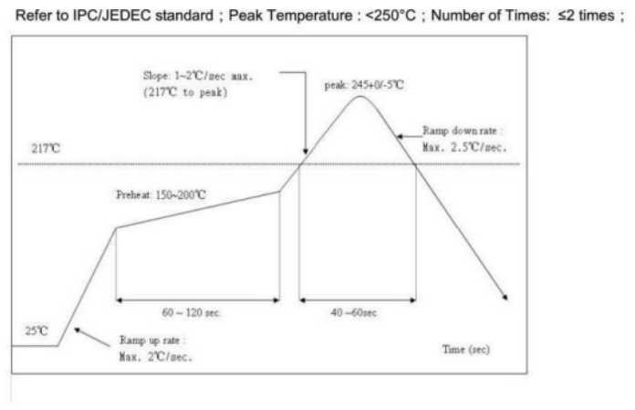
Figure 3. PCB Package Drawing Recommended furnace temperature curve
Is this page helpful?
YesFeedbackIs this page helpful?
YesFeedback


