TYLC4 Module Datasheet
TYLC4 is a low-power embedded Wi-Fi module developed by Hangzhou Tuya Information Technology Co., Ltd., which consists of a highly integrated RFID chip ESP8266 and a few peripheral components with built-in Wi-Fi network protocol stack and abundant library functions.
Product overview
TYLC4 is embedded with low power 32-bit CPU, 1 Mbyte flash memory and rich peripheral resources.
TYLC4 is a RTOS platform which integrates all the function libraries of Wi-Fi MAC and TCP/IP protocol, base on which, users are enabled to develop embedded Wi-Fi products according to their specific requirements.
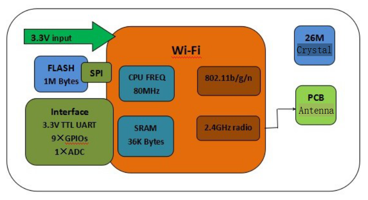
The functional principle of TYLC4 is shown as below:
Features
-
The embedded low-power 32-bit CPU can also be used as application processor
-
CPU Clock Speed: 80MHz and 160MHz
-
Working voltage: 3.0V-3.6V
-
Peripheral: 5×GPIOs, 1×UART
-
Wi-Fi connectivity
-
802.11 b/g/n
-
Channel: 1-14@2.4GHz
-
In support of WPA/WPA2 safe mode
-
A maximum output power of +20dBm in the mode of 802.11b
-
In support of STA/AP/STA+AP operating mode
-
In support of two distribution networks including SmartConfig and AP (Android and iOS devices included)
-
Onboard PCB plug-in PiFA antenna
-
Operating temperature: -20℃ to 125℃
-
Main applications
- Intelligent building
- Smart home/home appliances
- Smart power plug, intelligent light
- Industrial wireless control
- Baby monitor
- Webcam
- Intelligent public transportation
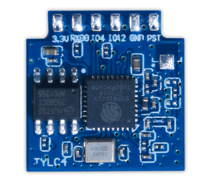
Module picture
-
Front:
-
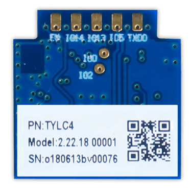
Negative:
Module interface
Size package
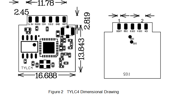
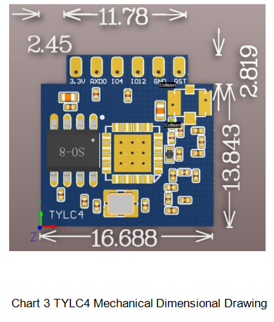
TYLC4 has two rows of pins and the spacing between each two pins is 2mm.
TYLC4 size: 16.69±0.35mm (W)×16.66±0.35mm (L) ×3.5±0.15mm (H). TYLC4 size is shown in figure2:
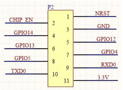
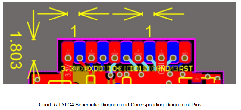
Pin definition
| Pin No. | Sign | IO type | Function |
|---|---|---|---|
| 1 | RST | I/O | Hardware reset pin (effective at low electrical level, with pull-up resistor inside) |
| 2 | EN | I | Module enabling pin needs to receive 3.3V power supply |
| 3 | GND | P | Power reference ground |
| 4 | GPIO14 | I/O | GPIO_14 |
| 5 | GPIO12 | I/O | GPIO_12 |
| 6 | GPIO13 | I/O | GPIO_13 |
| 7 | GPIO4 | I/O | GPIO_04 |
| 8 | GPIO5 | I/O | GPIO_05 |
| 9 | RXD0 | I/O | UART0_RXD 1 |
| 10 | TXD0 | O | UART0_TXD 1 |
| 11 | VCC | P | Module’s power pin (3.3V) |
- P stands for power pin, I/O stands for input/output pin.
- RST is only the module hardware reset pin, which cannot erase Wi-Fi distribution network information.
- UART0 is the user serial port; when the module is powered up, the serial port has information output and user can ignore it.
Test point definition
| Pin No. | Sign | IO Type | Function |
|---|---|---|---|
| - | TEST1 | I/O | GPIO2, used for module production test |
| - | TEST2 | I/O | GPIO0, used for module production test |
Electrical parameters
Absolute electrical parameters
| Parameter | Description | Minimum Value | Maximum Value | Unit |
|---|---|---|---|---|
| Ts | Storage temperature | -20 | 85 | ℃ |
| VCC | Supply voltage | -0.3 | 3.6 | V |
| Electrostatic Discharge Voltage (human model) | TAMB-25℃ | - | 2 | KV |
| Electrostatic Discharge Voltage (machine model) | TAMB-25℃ | - | 0.5 | KV |
Operating conditions
| Parameter | Description | Minimum Value | Typical Value | Maximum Value | Unit |
|---|---|---|---|---|---|
| Ta | Operating temperature | -20 | - | 125 | ℃ |
| VCC | Operating voltage | 3.0 | 3.3 | 3.6 | V |
| VIL | IO low electrical level input | -0.3 | - | VCC*0.25 | V |
| VIH | IO high electrical level input | VCC*0.75 | - | VCC | V |
| VOL | IO low electrical level output | - | - | VCC*0.1 | V |
| VoH | IO high electrical level output | VCC*0.8 | - | VCC | V |
| Imax | IO drive current | - | - | 12 | mA |
Wi-Fi transmitting power
| Sign | Parameter | Parameter | Parameter | Typical Value | Unit |
|---|---|---|---|---|---|
| Mode | Mode | Rate | Transmitting Power | ||
| IRF | 11b | 11Mbps | +17dBm | 220 | mA |
| IRF | 11g | 54Mbps | +15dBm | 110 | mA |
| IRF | 11n | MCS7 | +13dBm | 100 | mA |
Wi-Fi receiving power
| PowerSign | Mode | Rate | Typical Value | Unit |
|---|---|---|---|---|
| IRF | 11b | 11Mbps | 76 | mA |
| IRF | 11g | 54Mbps | 76 | mA |
| IRF | 11n | MCS7 | 76 | mA |
Power in operating mode
| Operating Mode | Operating Status, Ta=25℃ | Average Value | Maximum Value | Unit |
|---|---|---|---|---|
| Fast connection distribution network | When the module is in a state of fast connection distribution network, Wi-Fi indicator light flashes quickly | 80 | 151 | mA |
| Hot spot distribution network | When the module is in a state of hot spot distribution network, Wi-Fi indicator light flashes slowly | 90 | 451 | mA |
| Internet connection | When the module is with internet connection, Wi-Fi indicator light goes on | 58.5 | 411 | mA |
| Offline | When the module is offline, Wi-Fi indicator light goes out | 80 | 430 | mA |
RF characteristics
Basic RF characteristics
| Parameter | Detailed Description |
|---|---|
| Operating frequency | 2.412~2.484GHz |
| Wi-Fi standard | IEEE 802.11b/g/n (channel 1-14) |
| Data transmitting rate | 11b:1,2,5.5, 11 (Mbps) 11g:6,9,12,18,24,36,48,54(Mbps) 11n:HT20 MCS0~7 |
| Antenna type | PCB onboard plug-in antenna |
Wi-Fi output power
| Parameter | Minimum Value | Typical Value | Maximum Value | Unit | |
|---|---|---|---|---|---|
| RF average output power, 802.11b CCK Mode | 1M | - | 20 | - | dBm |
| RF average output power, 802.11g OFDM Mode | 54M | - | 17 | - | dBm |
| RF average output power, 802.11n OFDM Mode | MCS7 | - | 14 | - | dBm |
| Frequency Error | - | -10 | - | 10 | ppm |
Wi-Fi receiving sensitivity
| Parameter | Minimum Value | Typical Value | Maximum Value | Unit | |
|---|---|---|---|---|---|
| PER<8%,RX sensitivity, 802.11b CCK Mode | 1M | - | -91 | - | dBm |
| PER<10%,RX sensitivity, 802.11g OFDM Mode | 54M | - | -75 | - | dBm |
| PER<10%,RX sensitivity, 802.11n OFDM Mode | MCS7 | - | -72 | - | dBm |
Antenna
Antenna type
PCB board has reserved IPEX interfaces to receive antenna with IPEX terminals.
Reduction of antenna interference
When using antenna with IPEX terminals on the Wi-Fi module, to ensure the best Wi-Fi performance, it is recommended that the distance between the module antenna and other metal parts should be at least 10mm.
Packaging information and manufacturing instructions
Mechanical dimensions
PCB recommended package
Production instructions
- For the Tuya in-line module, wave soldering is most preferred and manual soldering is less preferred. After being unpacked, the module must be soldered within 24 hours. Otherwise, it must be put into the drying cupboard where the RH is not greater than 10%; or it needs to be packaged under vacuum again and record the exposure time (the total exposure time cannot exceed 168 hours).
- Wave soldering devices and materials:
- Wave soldering equipment
- Wave soldering fixture
- Constant-temperature soldering iron
- Tin bar, tin wire, and flux
- Thermal profiler
- Baking devices:
- Cabinet oven
- Anti-electrostatic and heat-resistant trays
- Anti-electrostatic and heat-resistant gloves
- The module needs to be baked in the following cases:
- The packaging bag is damaged before unpacking.
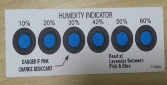
- There is no humidity indicator card (HIC) in the packaging bag.
- After unpacking, circles of 10% and above on the HIC become pink.
- The total exposure time has lasted for over 168 hours since unpacking.
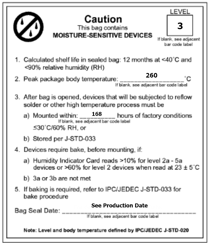
- More than 12 months have passed since the sealing of the bag.
- Baking settings:
- Temperature: 60°C and ≤ 5% RH for reel package and 125°C and ≤5% RH for tray package (please use the heat-resistant tray rather than plastic container)
- Time: 48 hours for reel package and 12 hours for tray package
- Alarm temperature: 65°C for reel package and 135°C for tray package
- Production-ready temperature after natural cooling: < 36°C
- Re-baking situation: If a module remains unused for over 168 hours after being baked, it needs to be baked again.
- If a batch of modules is not baked within 168 hours, do not use the wave soldering to solder them. Because these modules are Level-3 moisture-sensitive devices, they are very likely to get damp when exposed beyond the allowable time. In this case, if they are soldered at high temperatures, it may result in device failure or poor soldering.
- In the whole production process, take electrostatic discharge (ESD) protective measures.
- To guarantee the quality of products, you must pay attention to the following items: The amount of soldering flux, the height of the wave peak, whether the tin slag and copper content in the wave soldering tank exceed standards, whether the window and thickness of the wave soldering fixture are appropriate, and whether the wave soldering oven temperature curve is appropriate.
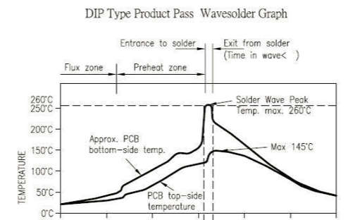
Recommended oven temperature curve and temperature
Set oven temperatures according to the following temperature curve of wave soldering. The peak temperature is 260°C±5°C.
Recommended soldering temperature:
| Suggestions on oven temperature curve of wave soldering | Suggestions on manual soldering temperature | ||
|---|---|---|---|
| Preheat temperature | 80 to 130 °C | Soldering temperature | 360±20°C |
| Preheat time | 75 to 100s | Soldering time | <3s/point |
| Peak contact time | 3 to 5s | NA | NA |
| Temperature of tin cylinder | 260±5°C | NA | NA |
| Ramp-up slope | ≤2°C/s | NA | NA |
| Ramp-down slope | ≤6°C/s | NA | NA |
Storage conditions
Storage conditions for a delivered module:
-
The moisture-proof bag is placed in an environment where the temperature is below 40°C and the relative humidity is lower than 90%.
-
The shelf life of a dry-packaged product is 12 months from the date when the product is packaged and sealed.
-
There is a humidity indicator card (HIC) in the packaging bag.
Is this page helpful?
YesFeedbackIs this page helpful?
YesFeedback


