BP5758D Driver
Overview
The BP5758D is a 5-channel dimmable linear constant-current LED driver with high-precision from the manufacturer Bright Power Semiconductor.
Features:
- High-voltage linear LED dimmer with 5 output channels.
- The maximum output current can be set for each channel separately, which can be up to 1 mA per step.
- Each channel has individually adjustable 1,024 grayscales.
- Ultra-low standby power. The operating current in sleep mode is less than 100 μA.
- Over-heating protection. If the temperature of the IC exceeds the threshold, the output current will be decreased automatically to ensure stable operation.
Development
-
The two pins of the I2C bus are integrated with a 15 kΩ pull-up resistor respectively. Because the freewheeling current is small, you need to add an external 4.7 kΩ pull-up resistor to the circuit.
-
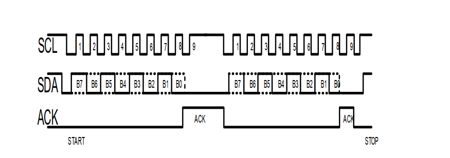
The communication protocol used by the BP5758 is not strictly the I2C protocol. Therefore, the sender should wait for an acknowledgment after transmitting each byte.
-
BP5758 supports direct bit addressing after byte 0. The lower 4 bits of byte 0 can be the start address. You can set the lower 4 bits to
0110to directly skip byte 1 to byte 6.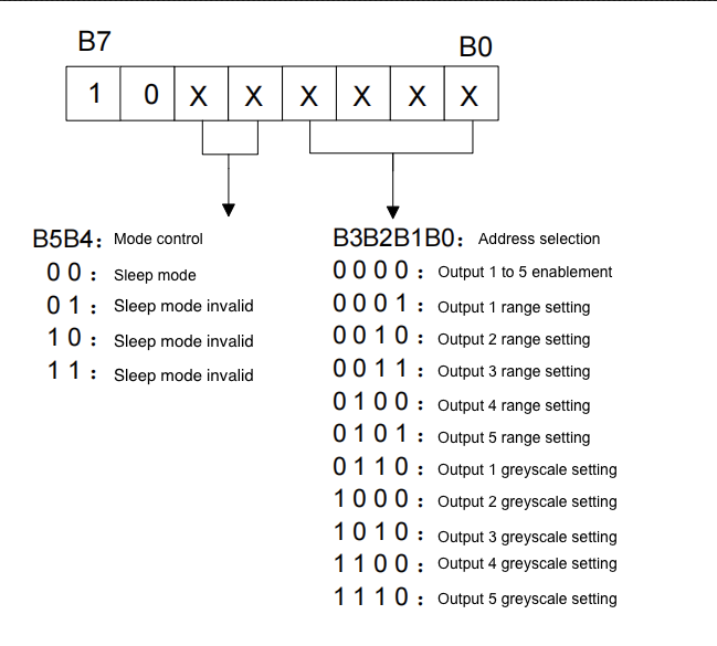
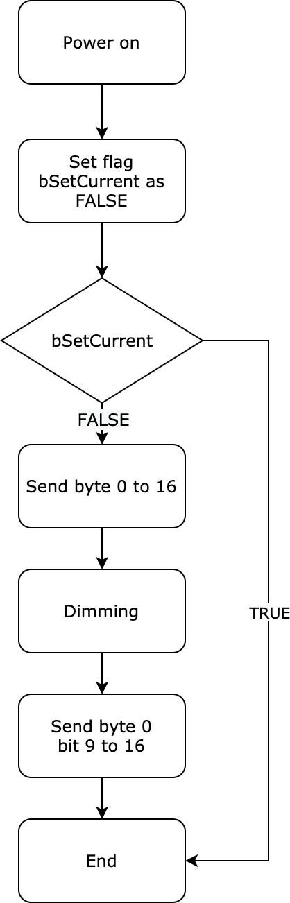
You can set the parameters such as current enablement, the maximum current, and the current range on the first-time initialization. This way, you can only set the greyscale value on the subsequent initialization. The following diagram shows the process.
No-code development
-
Log in to the Tuya Developer Platform.
-
Click Create.
-
Click the Standard Category tab and choose Lighting > Light Source.
-
Choose TuyaOS > No-Code Development. For protocol, choose Wi-Fi-Bluetooth and then select an RGB, RGBC, or RGBCW light.
-
Complete the required information and click Create.
-
Configure Function Definition and Device Panel as needed.
For more information, see Product Functions and Design App UI.
-
Under the Hardware Development tab, select CBU Wi-Fi & Bluetooth Module.
-
In the Product Hardware Configure, choose BP5758D for the Product Drive Mode.
For more information, see Select and Manage the Firmware Version.
-
Configure parameters for the driver.
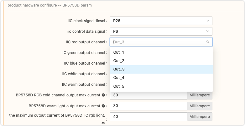
- You can specify the output channel for red, green, blue, cool white, and warm white as needed.
- The RGB current is taken as one parameter. You cannot configure red, green, and blue individually.
- Some parameters conflict with specific features so they cannot be configured individually. For example, the built-in gamma calibration is used to ensure no color shift occurs on RGB output, which makes obtaining color mixing data complicated.
FAQs
Why doesn’t the light come on after a quick turn off and on?
The dropout speed of BP5758D is faster than that of the module. Therefore, at the moment of power off, the module is not turned off actually. At this time, as the light is powered on, the BP5758D is reset. However, the module is not reset simultaneously so the register on the BP5758D is not configured. The BP5758D cannot run so the light does not come on. In this case, even though the light shows online in the mobile app, the control commands sent from the app do not work.
You can increase the speed of module discharging to ensure the dropout speed of the module is quicker than that of the BP5758D. Regarding the firmware, the module needs to configure the register on BP5758D before each data transmission.
Why can’t the light achieve the expected low power consumption in a turn-off state?
Check if you correctly configure the low power mode for the driver.
You can let both the MCU and the driver enter low power mode when the light is turned off to reduce the overall power consumption.
Why do crosstalk and dead pixels occur on RGB lights or RGB and white lights?
The I2C signal of the BP5758D is susceptible to electromagnetic interference due to improper PCB trace design.
The following lists the tracing guides for this driver:
- The SDA and SCL trace from the MCU to the BP5758D and the ground wire circuit should be as short as possible in order to reduce coupling with other noises. Try not routing SDA and SCL traces under the module. Keep the traces away from the antenna area.
- The distance between high-voltage traces and low-voltage traces must be optimized.
- The copper foil area of the ground wire should be maximized to reduce thermal resistance and improve the heat dissipation performance.
Is this page helpful?
YesFeedbackIs this page helpful?
YesFeedback


