Environment Setup
This topic describes how to set up a development environment. We use the BTU module to walk you through how to get the SDK, install IDE, and use the flashing tool and debugger.
Get SDK
Make sure you have created a product on the Tuya Developer Platform. Go to the Hardware Development step, select a network module, and then download the SDK in the Download Documents section.
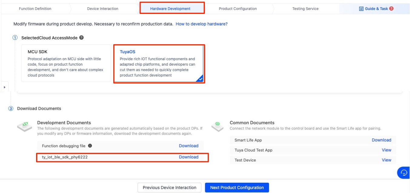
Extract the downloaded file. You will get the SDK tuya-ble-sdk-demo-project-tlsr8253. Open the SDK folder and check out the README. Complete the necessary preparations as instructed in the README, such as downloading the SDK from the chip manufacturer.
Compilation environment
After application development, you need to compile the code to generate an executable file (the firmware) for flashing. The following table lists the IDE for different chip platforms. Install an IDE based on your choice.
| Manufacturer | Chipset platform | IDE |
|---|---|---|
| Telink | TLSR825x | Eclipse (IDE for TLSR8 Chips) |
| Nordic Semiconductor | nRF52832 | MDK-ARM Keil µVision |
| Phyplus | PHY6222 | MDK-ARM Keil µVision |
| Cypress | PSoC 63 | PSoC Creator |
| Beken | BK3431Q | MDK-ARM Keil µVision |
| Freqchip | FR8018H | MDK-ARM Keil µVision |
| … | … | … |
This section uses BTU module to demonstrate the IDE setup. BTU modules are based on Telink’s TLSR825x.
-
Download IDE: Download the
IDE for TLSR8 Chipsfrom the Telink website.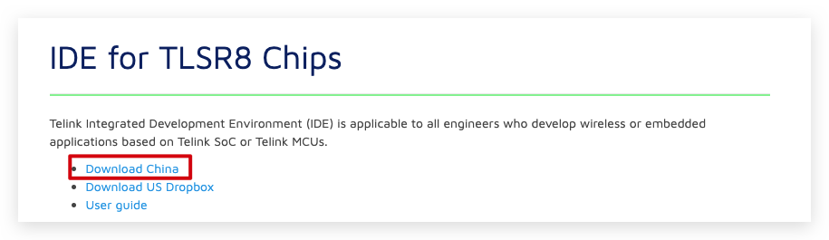
-
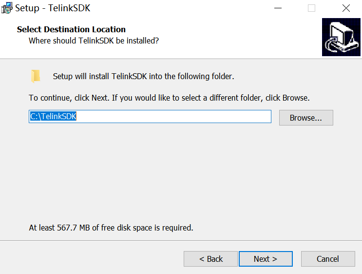
Install IDE: Finish installation as instructed in the
readme.txt. Make sure to run the installer as an administrator and have the IDE installed on the C: drive. -
-
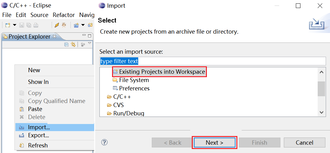
Import project: Import the SDK to the IDE.
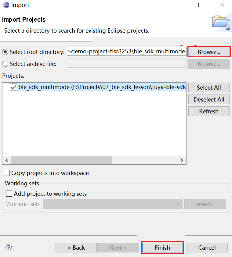
-
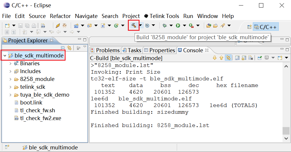
Test compilation: Verify whether compilation works as expected.
Flashing environment
Flash firmware to and authorize the module to implement cloud connection. This section describes the preparation steps to perform before firmware flashing. For more information, see the Flash Firmware and Authorize Module.
-
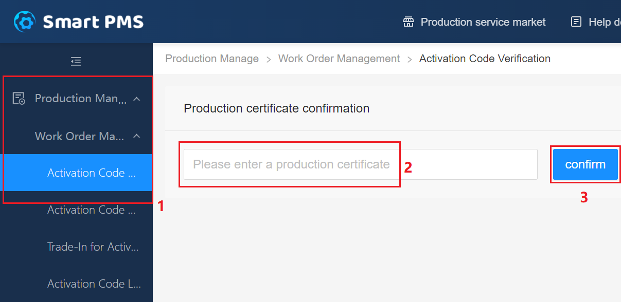
Register with the PMS.
Open the PMS system. Click Free Registration to sign up.
-
Download and install Production Toolkit.
This kit includes the Cloud Module Burning Authorization Platform. You can download it from the PMS.
-
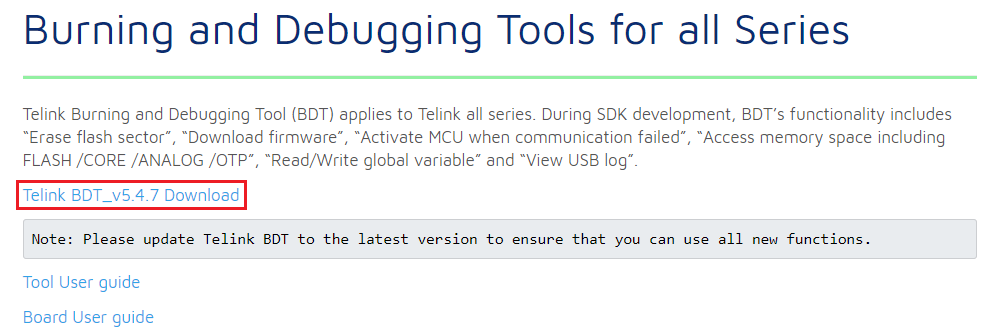
Download and install the chip-specific flashing tool.
Generally, you can download the dedicated flashing tool for your chips from its official website. For BTU modules, we need to install Telink BDT.
-
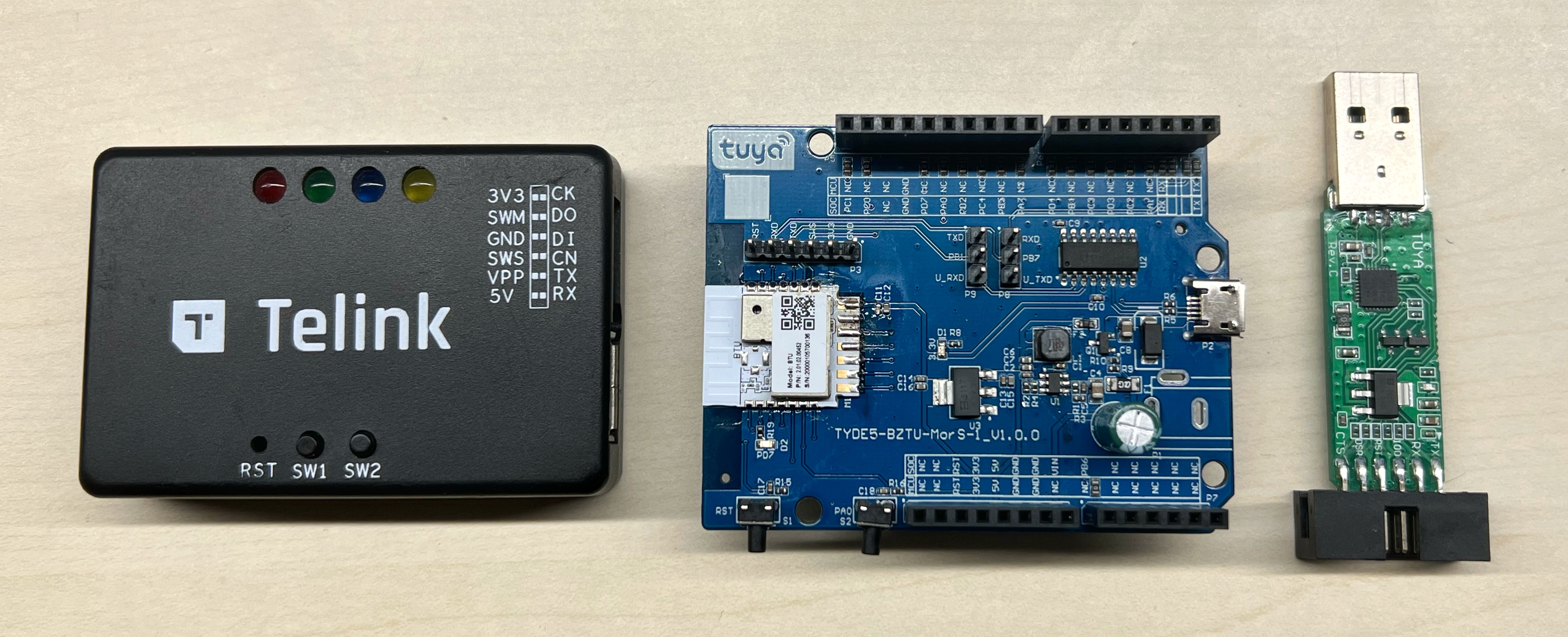
Prepare a development board with a Tuya Bluetooth module, chip-specific programmer, and USB to TTL converter.
We use a Sandwich development board (with BTU module) for debugging. If the chip manufacturer has a dedicated programmer for its flashing tool, you need to get it ready. A USB to TTL converter is required to connect the developed board to the host.
-
Connect the development board with the programmer.
-
Connect to the programmer
Development board (BTU module) Telink programmer 3V3 3V3 SWS SWM GND GND -
Connect the development board with the USB to TTL converter.
Development board (BTU module) USB to TTL converter 3V3 3V3 TXD RX RXD TX GND GND
-
Test environment
Device logs are broken down into two types, namely local logs and cloud logs, which can help troubleshoot issues occurred when you debug code.
Local logs
The logging feature is disabled by default. In the SDK, set the value of TUYA_APP_LOG_ENABLE and TY_LOG_ENABLE to 1 to enable logging. Then, you can check logs using the USB to TTL converter and Debugging Assistant.
/* custom_tuya_ble_config.h  Set the logging feature /Disable */
#define TUYA_APP_LOG_ENABLE   1	/* 0: disable; 1: enable */

/* board.h Set the logging feature /Disable (platform-specific) */
#define TY_LOG_ENABLE         1	/* 0: disable; 1: enable */
Since the pin configurations vary depending on devices, you need to change the pin used for log print accordingly. For example, if you use TLSR825x, you need to modify the pin configuration in the file telink_sdk\vendor\8258_module\app_config.h.
/* Original code */
#define DEBUG_INFO_TX_PIN     GPIO_PC0
#define PC0_FUNC              AS_GPIO
#define PC0_INPUT_ENABLE      0
#define PC0_OUTPUT_ENABLE     1
#define PC0_DATA_OUT          1

/* After modification */
#define DEBUG_INFO_TX_PIN     GPIO_PC3
#define PC3_FUNC              AS_GPIO
#define PC3_INPUT_ENABLE      0
#define PC3_OUTPUT_ENABLE     1
#define PC3_DATA_OUT          1
Cloud logs
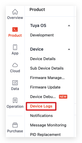
After a device is connected to the cloud, you can check the log of data communication between the device and the cloud on the Tuya Developer Platform. In the left navigation pane, choose Product > Device Logs. Search for the target device by Device ID and check logs.
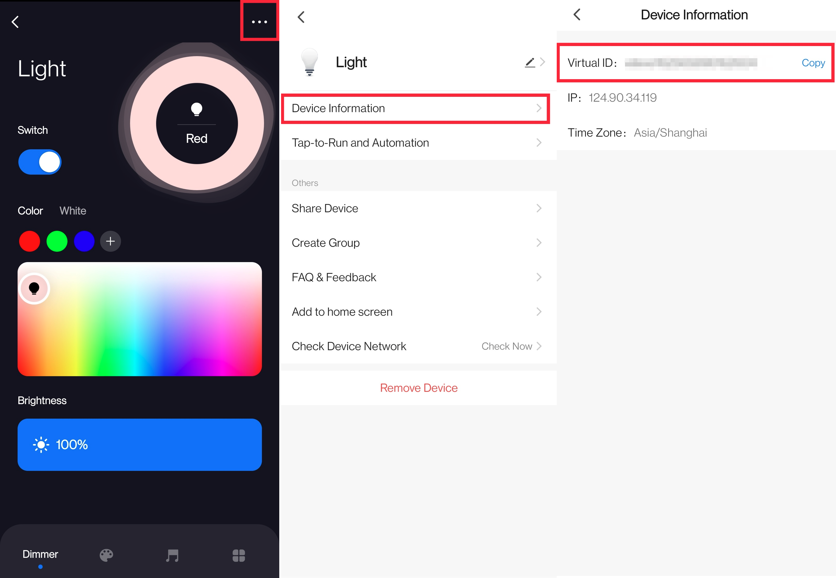
To find the device ID, open the SmartLife app and enter the control panel of the device. Tap … in the top right corner and tap Device Information.
Things to note
The test mode is enabled by default in the SDK. You need to disable it by setting the value of TUYA_BLE_SDK_TEST to 0 when you work on product development.
/* tuya_ble_sdk_test.h */
#define TUYA_BLE_SDK_TEST	0	/* 0: disable; 1: enable */
Is this page helpful?
YesFeedbackIs this page helpful?
YesFeedback


