Extended Support for Bluetooth Beacon Remotes
The generic Bluetooth Low Energy (LE) module receives control commands from Bluetooth beacon remotes and transmits them to the MCU for device control.
Scenarios
- This function applies to mains-powered devices, such as home appliances and lighting products, as well as devices that are controlled with a remote.
Features
- Support pairing Bluetooth LE devices through a mobile phone and gateway.
- Local and group control of Bluetooth beacon remotes.
- Identity authentication mechanism and data encryption.
- Pairing is not necessary for a device to be controlled. The remote can control an unpaired device, just like a 2.4 GHz remote, unless it fails to authenticate with the proxy of the target device.
- The groups of a remote can be removed from the mobile app.
Get started
Prepare hardware and software
- Generic Bluetooth LE module
- Bluetooth beacon remote
- Module Debugging Assistant
Step 1: Select Bluetooth firmware
Select the generic Bluetooth firmware that supports Bluetooth beacon remotes.
-
Log in to the Tuya Developer Platform.
-
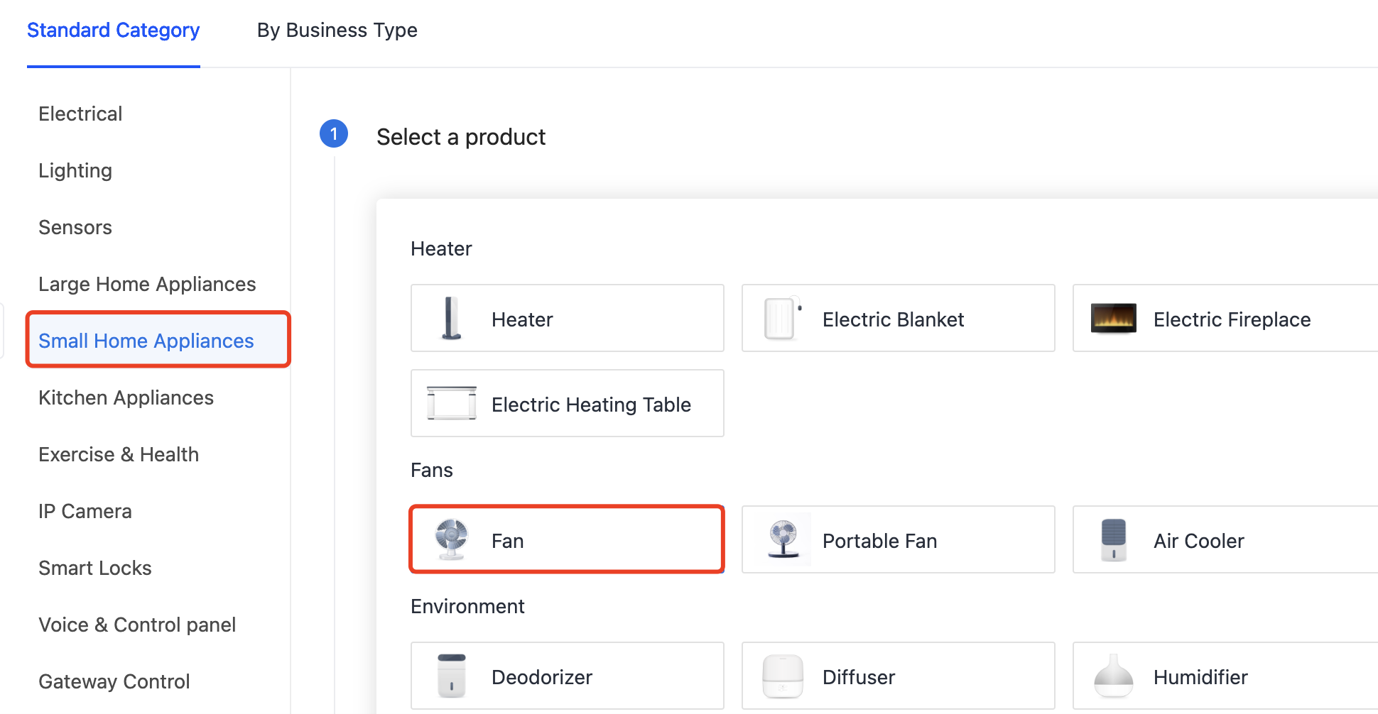
Navigate to the Create Product page.
-
Determine the product category for your devices. For example, Small Home Appliances > Fan.
-
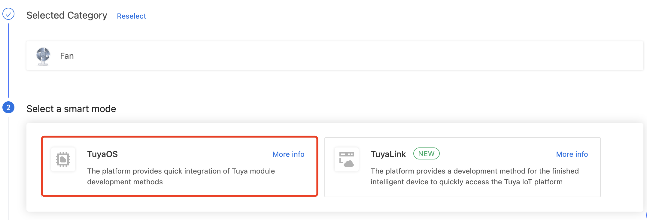
Choose TuyaOS for smart mode.
-
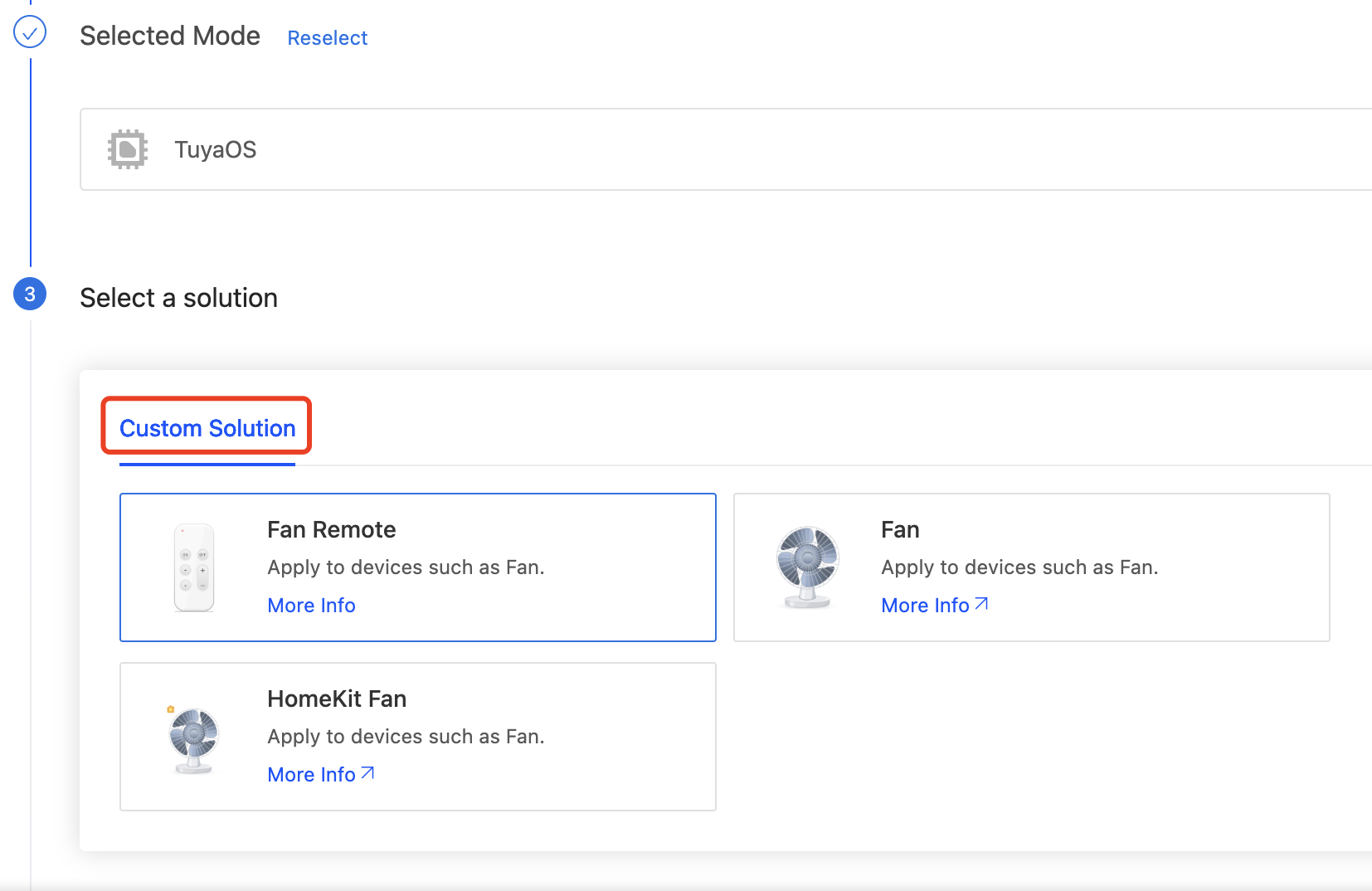
Under the Custom Solution tab, select Fan or Fan Remote. Complete the required information and click Create.
-
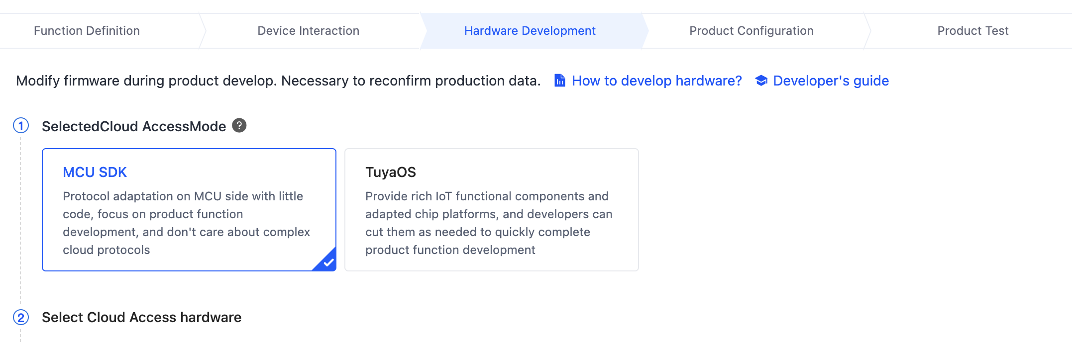
In Hardware Development, choose MCU SDK for cloud access mode.
The Telink series and BPU modules have been adapted for Bluetooth beacon remotes. The following is an incomplete list of deliverables that support Bluetooth beacon remotes. If you cannot find the required deliverable, submit a service ticket to request listing it.
The firmware that supports Bluetooth beacon remotes:
- Firmware key
keyyayjm, firmware version 2.3.0 and later. - Firmware key
keyysck3, firmware version 2.1.1 and later.
- Firmware key
Step 2: Prepare the Bluetooth beacon remote
Purchase a remote or develop one with Tuya Bluetooth beacon remote SDK.
Step 3: Try out features
With Tuya’s Module Debugging Assistant, follow the steps below to try out the features of the Bluetooth beacon remote.
-
The module does not support Bluetooth beacon remote by default. You need to enable this feature through the Bluetooth remote control configuration (0xC100). Example:
MCU to module:
55 AA 00 C1 00 03 00 07 01 CB. Enable the support for Bluetooth beacon remotes, always open for pairing, and lighting control commands.Module to MCU:
55 AA 00 C1 00 02 00 00 C2. The configuration is successful and stored in non-volatile memory. -
The remote sends a command to pair with the module. After successful pairing, the module prints the remote binding information. Example:
Module to MCU:
55 AA 00 C1 00 03 02 01 02 C8. The remote is paired and assigned a group ID of 2. -
The remote turns on and off the light.
According to the Bluetooth remote control commands,
0xFFrepresents the general category, and0x04indicates on/off (0x00for off and0x01for on).Module to MCU:
55 AA 00 C1 00 07 01 FF 04 00 00 00 00 CB, instructing the MCU to turn off the light.Module to MCU:
55 AA 00 C1 00 07 01 FF 04 01 00 00 00 CC, instructing the MCU to turn on the light. -
Remove the remote locally. When a Bluetooth beacon remote is removed locally, the module will notify the MCU of the change in remote binding status.
Module to MCU:
55 AA 00 C1 00 03 02 00 00 C5. -
Add a device to the SmartLife app.
-
The remote sends a pairing command to the module.
Module to MCU:
55 AA 00 C1 00 03 02 01 02 C8. The remote is paired and assigned a group ID of 2. -
The module initiates proxy authentication with the remote. After successful authentication, the remote will be displayed on the app panel. If authentication fails, the pairing relationship with the remote will be deleted.
-
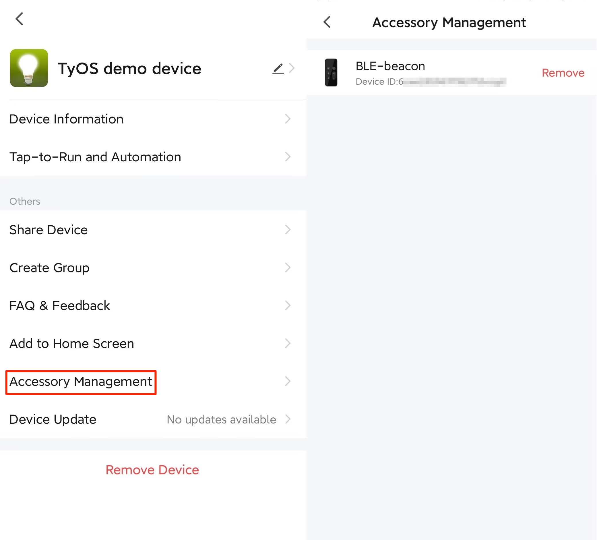
Remove a remote from the app. When a Bluetooth beacon remote is removed from the app, the module will notify the MCU of the change in remote binding status.
Module to MCU:
55 AA 00 C1 00 03 02 00 00 C5.
Excerpts from the protocol
Bluetooth remote control configuration (0xC100)
- This feature allows the user to control a device using a physical Bluetooth remote. It is disabled by default.
- If you choose the module self-processing of Bluetooth remote pairing request for the
CFGfield, the module allows pairing with a Bluetooth remote within 30 seconds of powering on. - If you choose the MCU and module co-processing of Bluetooth remote pairing request for the
CFGfield, the MCU can accept or reject the pairing request. - Up to five devices can be paired with the Bluetooth remote control. Otherwise, pairing will fail.
- With the Bluetooth remote control enabled, the module will not enter the low power mode. You need to call the command to disable Bluetooth remote control before the module enters the low power mode and enable the feature after the module exits the low power mode.
- The RF test command (0x0E) can affect the scanning function. Therefore, enable the Bluetooth remote control after completing the RF test.
- The configuration is stored in the nonvolatile memory.
The MCU sends the following data.
| No. | Bytes | Field | Description |
|---|---|---|---|
| 0 1 |
2 | Header | 0x55 0xAA |
| 2 | 1 | Version number | 0x00 |
| 3 | 1 | Command (CMD) | 0xC1 |
| 4 5 |
2 | Data length | 0x00 0x03 |
| 6 | 1 | Subcommand | 0x00 |
| 7 8 |
2 | Data | Data[0]: CFG Data[1]: Category ID |
| 9 | 1 | CRC8 | Start from the header, add up all the bytes, and then divide the sum by 256 to get the remainder. |
CFG: used to set the Bluetooth remote control feature.
bit0:0: disables the Bluetooth remote control.1: enables the Bluetooth remote control.bit1:0: indicates module self-processing of Bluetooth remote pairing request.1: indicates MCU and module co-processing of Bluetooth remote pairing request.bit2:0: rejects the pairing request from the Bluetooth remote.1: accepts the pairing request from the Bluetooth remote. This bit applies whenbit1is set to1.- Other bits are reserved. Set them to
0.
Category ID:
- Generic: Oxff
- Lighting product: 0x01
- Socket/power strip: 0x02
- Curtain switch: 0x03
- Drying rack: 0x04
- Fan: 0x05
- Bathroom heater: 0x06
- Air conditioner: 0x07
- Garage door opener: 0x08
- Water valve: 0x09
- Disinfector: 0x0A
- Thermostat plug: 0x0B
- Dimmer switch: 0x0C
- Scene socket: 0x0D
- Switch: 0x0E
- Smart curtain switch module: 0x0F
Example: 55 AA 00 C1 00 03 00 01 05 C9, meaning to enable the Bluetooth remote control.
The module returns the following data.
| No. | Bytes | Field | Description |
|---|---|---|---|
| 0 1 |
2 | Header | 0x55 0xAA |
| 2 | 1 | Version number | 0x00 |
| 3 | 1 | Command (CMD) | 0xC1 |
| 4 5 |
2 | Data length | 0x00 0x02 |
| 6 | 1 | Subcommand | 0x00 |
| 7 | 1 | Data |
|
| 8 | 1 | CRC8 | Start from the header, add up all the bytes, and then divide the sum by 256 to get the remainder. |
Bluetooth remote control data notification (0xC101)
- This feature applies when you enable the Bluetooth remote control.
- For more information, see Bluetooth remote control commands.
The module sends the following data.
| No. | Bytes | Field | Description |
|---|---|---|---|
| 0 1 |
2 | Header | 0x55 0xAA |
| 2 | 1 | Version number | 0x00 |
| 3 | 1 | Command (CMD) | 0xC1 |
| 4 5 |
2 | Data length | 0x00 0x07 |
| 6 | 1 | Subcommand | 0x01 |
| Data |
|
||
| 13 | 1 | CRC8 | Start from the header, add up all the bytes, and then divide the sum by 256 to get the remainder. |
The MCU returns the following data.
| No. | Bytes | Field | Description |
|---|---|---|---|
| 0 1 |
2 | Header | 0x55 0xAA |
| 2 | 1 | Version number | 0x00 |
| 3 | 1 | Command (CMD) | 0xC1 |
| 4 5 |
2 | Data length | 0x00 0x01 |
| 6 | 1 | Subcommand | 0x01 |
| 7 | 1 | CRC8 | Start from the header, add up all the bytes, and then divide the sum by 256 to get the remainder. |
Bluetooth remote control binding notification (0xC102)
This feature applies when you enable the Bluetooth remote control.
The module sends the following data.
| No. | Bytes | Field | Description |
|---|---|---|---|
| 0 1 |
2 | Header | 0x55 0xAA |
| 2 | 1 | Version number | 0x00 |
| 3 | 1 | Command (CMD) | 0xC1 |
| 4 5 |
2 | Data length | 0x00 0x03 |
| 6 | 1 | Subcommand | 0x02 |
| 7 8 |
2 | Data | Data[0]: 0x00: Unbound. 0x01: Bound. Data[1]: Group ID. |
| 9 | 1 | CRC8 | Start from the header, add up all the bytes, and then divide the sum by 256 to get the remainder. |
Bluetooth remote control commands
| Command (1 byte) |
Generic command (1 byte) |
Command data (4 bytes). Padded with 0 if needed | |
|---|---|---|---|
| Category ID | |||
| Generic: 0xFF Individual category Lighting product: 0x01 Socket/power strip: 0x02 Curtain switch: 0x03 Drying rack: 0x04 Fan: 0x05 Bathroom heater: 0x06 Air conditioner: 0x07 Garage door opener: 0x08 Water valve: 0x09 Disinfector: 0x0A Thermostat plug: 0x0B Dimmer switch: 0x0C Scene socket: 0x0D Switch: 0x0E Smart curtain switch module: 0x0F |
Send key values: 0x01 |
Byte 1: Button behavior (0 – Single press. 1 – Double press. 2 – Long press. 3 – Press and hold. 4 – Press and release) Byte 2: The key value. |
|
| Switch: 0x04 | Byte 1: 0 – Turn off. 1 – Turn on. 2 – Pause. Byte 2: The number of gangs. 0 represents the main control. |
||
| Add favorites: 0x05 | Byte 1: 1 – Favorite a state. 2 – Go to a specified favorite. Byte 2: The ID of a favorite, ranging from 0 to 3. |
||
| Countdown timer: 0x06 | Bytes 1 to 2: The countdown time, in seconds and big-endian format. 0 indicates canceling the countdown timer. Byte 3: The action to run when the countdown timer is done. (Reserved byte) |
||
| One-click group query: 0x07 | The sub-device advertises the information about the added group. | ||
| Light on/off: 0x08 | Byte 1: 0 – Turn off. 1 – Turn on. Byte 2: 0 – The main switch. 1 – White light switch. 2 – Colored light switch. |
||
| Brightness adjustment: 0x09 | Byte 1: 0 – Brightness value. 1 – Brightness up. 2 – Brightness down. Byte 2: 0 – Brightness of the current mode. 1 – Brightness of white light. Byte 3: When Byte 1 is 0, this byte indicates brightness percentage (1 to 100%). When Byte 1 is 1 or 2, this byte indicates the step value of brightness (1 to 100%). |
||
| Stepless brightness adjustment: 0x0A | Byte 1: 0 – Start incrementing. 1 – Start decrementing. 2 – Stop adjustment. Byte 2: 0 – Brightness of the current mode. 1 – Brightness of white light. Byte 3: Rate (adjustment percentage per second) Byte 4: The target value. |
||
| Color temperature adjustment: 0x0B | Byte 1: 0 – Color temperature value. 1 – Color temperature up. 2 – Color temperature down. Byte 2: When Byte 1 is 0, this byte indicates color temperature percentage (0 to 100%). When Byte 1 is 1 or 2, this byte indicates the step value of color temperature (0 to 100%). |
||
| Stepless color temperature adjustment: 0x0C | Byte 1: 0 – Start incrementing. 1 – Start decrementing. 2 – Stop adjustment. Byte 2: Rate (adjustment percentage per second) Byte 3: The target value. |
||
| Color adjustment: 0x0D | Byte 1: 0 – Relative transition. 1 – The specified color. 2 – Start cycling adjustment. 3 – Stop cycling adjustment. Byte 2: The ID of the specified color when Byte 1 is 1. |
||
| Hue adjustment: 0x0E | Byte 1: 0 – Hue value. 1 – Hue up. 2 – Hue down. Byte 2: When Byte 1 is 0, this byte indicates hue percentage (0 to 100%). When Byte 1 is 1 or 2, this byte indicates the step value of hue (0 to 100%). |
||
| Stepless hue adjustment: 0x0F | Byte 1: 0 – Start incrementing. 1 – Start decrementing. 2 – Stop adjustment. Byte 2: Rate (adjustment percentage per second) Byte 3: The target value. |
||
| Saturation adjustment: 0x10 | Byte 1: 0 – Saturation value. 1 – Saturation up. 2 – Saturation down. Byte 2: When Byte 1 is 0, this byte indicates saturation percentage (0 to 100%). When Byte 1 is 1 or 2, this byte indicates the step value of saturation (0 to 100%). |
||
| Stepless saturation adjustment: 0x11 | Byte 1: 0 – Start incrementing. 1 – Start decrementing. 2 – Stop adjustment. Byte 2: Rate (adjustment percentage per second) Byte 3: The target value. |
||
| Value adjustment: 0x12 | Byte 1: 0 – Value. 1 – Value up. 2 – Value down. Byte 2: When Byte 1 is 0, this byte indicates value percentage (1 to 100%). When Byte 1 is 1 or 2, this byte indicates the step value of value (1 to 100%). |
||
| Stepless value adjustment: 0x13 | Byte 1: 0 – Start incrementing. 1 – Start decrementing. 2 – Stop adjustment. Byte 2: Rate (adjustment percentage per second) Byte 3: The target value. |
||
| HSV (hue, saturation, value) adjustment: 0x14 | Byte 1: Hue percentage (0 to 100%) Byte 2: Saturation (0 to 100%) Byte 3: Value percentage (1 to 100%) |
||
| Scene adjustment: 0x15 | Byte 1: 0 – Relative transition. 1 – The specified scene. 2 – Start cycling adjustment. 3 – Stop cycling adjustment. Byte 2: The ID of the specified scene when Byte 1 is 1. |
||
| Lighting mode selection: 0x16 | Byte 1: 1 – Night light mode. | ||
| Motor rotation adjustment: 0x20 | Byte 1: 0 – Clockwise rotation. 1 – Counterclockwise rotation. 2 – Pause. Byte 2: Travel percentage (0 to 100%). 0 – Continuous rotation. Byte 3: The number of channels. 0 represents the total channel. |
||
| Motor travel setting: 0x21 | Byte 1: 0 – The start position. 1 – The fine-tuning position. 2 – The end position. Byte 2: 0 – The up limit. 1 – The down limit. 2 – The intermediate limit. Byte 3: The number of channels. 0 represents the total channel. |
||
| Movement speed adjustment: 0x22 | Byte 1: 0 – Speed. 1 – Step increment. 2 – Step decrement. Byte 2: The specified speed or step value of speed. Byte 3: The number of channels. 0 represents the total channel. |
||
| Stepless movement speed adjustment: 0x23 | Byte 1: 0 – Start incrementing. 1 – Start decrementing. 2 – Stop adjustment. Byte 2: Rate (adjustment percentage per second) Byte 3: The target value. Byte 4: The number of channels. 0 represents the total channel. |
||
| Temperature adjustment: 0x24 | Byte 1: 0 – The temperature value. 1 – Temperature up. 2 – Temperature down. Bytes 2 to 3: When Byte 1 is 0, this byte indicates the specified temperature. When Byte 1 is 1 or 2, this byte indicates the step value of temperature. The 2-byte temperature value is stored in big-endian. The most significant bit represents the sign (minus or plus) and the rest of the bits represent the number. The number multiplied by 0.1°C is the actual temperature. |
||
| Stepless temperature adjustment: 0x25 | Byte 1: 0 – Start incrementing. 1 – Start decrementing. 2 – Stop adjustment. Byte 2: Rate (adjustment percentage per second) Bytes 3 to 4: The target value of temperature, which is calculated the same as above. |
||
| Humidity adjustment: 0x26 | Byte 1: 0 – Humidity value. 1 – Humidity up. 2 – Humidity down. Byte 2: The specified humidity. |
||
| Stepless humidity adjustment: 0x27 | Byte 1: 0 – Start incrementing. 1 – Start decrementing. 2 – Stop adjustment. Byte 2: Rate (adjustment percentage per second) Byte 3: The target value. |
||
| Custom command | |||
Custom category (1 byte) |
Custom command (1 byte) |
Parameter (3 bytes) |
|
Lights: 0xFF |
RGBY (red, green, blue, yellow) adjustment:0x01 |
Byte 1: 0 – Change color to red. 1 – Change color to green. 2 – Change color to blue. 3 – Change color to yellow. |
|
Fan: 0xFE |
Fan mode: 0x01 |
Byte 1: 0 – Manual adjustment. 1 – Natural wind. 2: Sleep wind. |
|
Bathroom heater: 0xFD |
Bathroom heater mode: 0x01 |
Byte 1: 0 – Heating. 1 – Ventilation. 2 – Drying. 3 – Fan. |
|
Air conditioner: 0xFC |
Sleep: 0x01 |
Byte 1: 0 – Off. 1 – On. |
|
FAQs
Q: How to configure the remote control function (0xC100)?
A: The CFG field specifies whether to allow the product to be always open for pairing with a remote control. It is highly recommended to allow the remote control to be paired only within 30 seconds of powering on. This can be done by setting bit1 to 0. To extend the pairing time, adjust bit1 and bit2 according to your needs.
It is not recommended to allow the device to be always open for pairing with a remote control. This can result in uncertainty regarding the target device, which ultimately compromises the system’s security.
This configuration policy enables you to restrict the pairing time window after device startup to enhance product security and stability.
Q: What are the common considerations for the remote control?
-
For example, one light product can support up to five remote controls.
-
A remote control can support up to eight buttons (eight groups).
-
The replacement logic: Assume that the remote control is paired with the light in home A first and then with the light in home B. The pairing relationship between the remote control and home A will be removed from the cloud. When the light in home A goes online, it will be instructed to delete its pairing with the remote control. Then, the remote control cannot control the light in home A.
If you have any problems with TuyaOS development, you can post your questions in the Tuya Developer Forum.
Reference
Is this page helpful?
YesFeedbackIs this page helpful?
YesFeedback


