Serial Communication Protocol
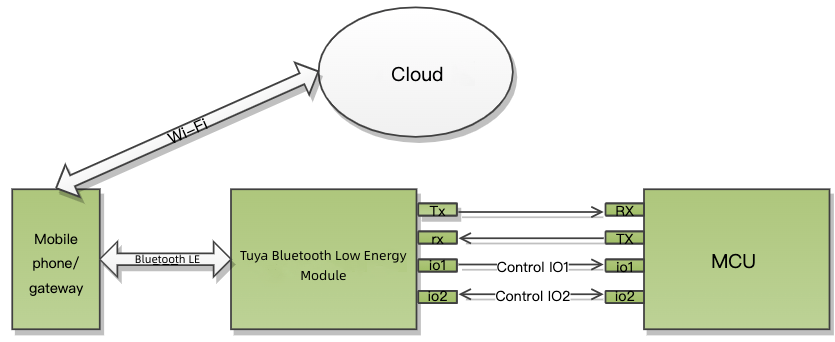
This topic describes the serial protocol that is used to implement serial communication between Tuya’s Bluetooth module and the third-party MCU, as shown in the following diagram.
Serial communication
-
Baud: 9600/115200 bps
-
Data bit: 8
-
Parity check: none
-
Stop bit: 1
-
Data flow control: none
After the Bluetooth module is powered on or restarted, it will start automatic baud rate detection. The module sends a heartbeat packet to the MCU at the baud rate configured last time. It changes to another baud rate at the next heartbeat interval and so on.
If the module receives the correct response from the MCU, it will stop baud rate detection and write the current serial port configuration to the flash memory. Some legacy firmware versions do not support automatic baud rate detection.
Terms
| Term | Description |
|---|---|
| Data point (DP) | A data point (DP) is an abstract representation of a product function. For more information, see Product Functions. |
| Product ID (PID) | A product is an abstract representation of a collection of product functions. Each product created on the Tuya Developer Platform is assigned a unique PID that is associated with the product information, including DPs, app control panel, and purchase information. |
| Bind Bluetooth device | Bind a Bluetooth device with an app account through the Tuya-specific Bluetooth protocol to register the device to the cloud. |
| Unbind Bluetooth device | Unbind a Bluetooth device from an app account. The device will be in the unbound and not connected state. |
| Reset Bluetooth device | Unbind a Bluetooth device and clear the user data by using the app. The difference between resetting and unbinding is whether the user data is cleared. |
| Bluetooth connection | Indicate a Bluetooth device is in the connection state in the link layer. |
| Bluetooth advertising | Indicate a Bluetooth device is in the advertising state in the link layer. |
| Bluetooth pairing mode | Indicate a Bluetooth device that is not bound and connected is advertising specified data, allowing the mobile app to discover the advertising device. |
| Bluetooth bound and connected | Indicate a Bluetooth device is online. The device is bound with and establishes a secure connection with the app through the Tuya-specific Bluetooth protocol. |
| Bluetooth bound but not connected | Indicate a Bluetooth device is offline. The device is bound with but not connected to the app. |
| Bluetooth gateway online | The gateway connection status depends on the logic to determine the online/offline status, which can vary depending on the gateway for use.
|
Packet structure
| No. | Bytes | Field | Description |
|---|---|---|---|
| 0 1 |
2 | Header | 0x55 0xAA |
| 2 | 1 | Version number | The protocol version. |
| 3 | 1 | Command (CMD) | The frame type. |
| 4 5 |
2 | Data length (Len) | Upper 8 bits Lower 8 bits |
| 6 to 6+Len-1 | Len | Data | |
| 6+Len | 1 | CRC8 | Start from the header, add up all the bytes, and then divide the sum by 256 to get the remainder. |
All data greater than one byte is transmitted in big-endian format.
DP format
| Field | Bytes | Description |
|---|---|---|
| dp_id | 1 | The ID of a DP. |
| dp_type | 1 | The data type of a DP. |
| dp_data_len | 2 | The data length of a DP. |
| dp_data_value | dp_data_len | The data of a DP. |
The value range and description of dp_type (cloud defined):
| dp_type | Value | Bytes | Description |
|---|---|---|---|
| raw | 0x00 | 1 to 255 | The raw data in hexadecimal format. |
| bool | 0x01 | 1 | Boolean type. |
| value | 0x02 | 4 | Integer type. |
| string | 0x03 | 0 to 255 | String type. It might be empty. |
| enum | 0x04 | 1 | Enum type |
| bitmap | 0x05 | 1/2/4 | Data greater than one byte is transmitted in big-endian format. |
Firmware types
- To support features specific to a product category, a range of extended protocols are provided to help you implement the required features on top of the generic firmware. The Bluetooth protocols include the generic one as well as protocols in terms of low power, generic smart lock features, extended features, and Bluetooth-specific features.
- Typically, all the generic firmware supports the generic protocol. The support for other protocols depends on the firmware for use.
The following table lists the firmware support information.
| Product category | Chip | Module |
|---|---|---|
| Basis |
|
|
| Locks |
|
|
| Shared devices |
|
|
| Sensors |
|
|
Note that the generic firmware support for specific protocols depends on product categories and models. If you have any questions about protocols, submit a service ticket.
Generic protocol
Detect heartbeat (0x00)
-
After power on, the module will send a heartbeat packet to the MCU every 3 seconds. If the MCU correctly responds to a heartbeat, it indicates the MCU works properly. After the first-time heartbeat communication, the module will send the MCU a command to get product information.
-
The MCU can determine whether the module works properly by the regular heartbeat check. If the MCU does not receive a heartbeat packet as expected, it can use the reset pin to reset the module.
-
After getting the MCU information, the module checks the heartbeat every 10 seconds in standard power mode. In low power mode, there is no heartbeat check.
The Telink Bluetooth modules do not perform heartbeat checks both in low power mode and after getting the MCU information in standard power mode. They cannot detect whether the MCU has been restarted.
The module sends the following data.
| No. | Bytes | Field | Description |
|---|---|---|---|
| 0 1 |
2 | Header | 0x55 0xAA |
| 2 | 1 | Version number | 0x00 |
| 3 | 1 | Command (CMD) | 0x00 |
| 4 5 |
2 | Data length. | 0x00 0x00 |
| 6 | 1 | CRC8 | Start from the header, add up all the bytes, and then divide the sum by 256 to get the remainder. |
The MCU returns the following data.
| No. | Bytes | Field | Description |
|---|---|---|---|
| 0 1 |
2 | Header | 0x55 0xAA |
| 2 | 1 | Version number | 0x00 |
| 3 | 1 | Command (CMD) | 0x00 |
| 4 5 |
2 | Data length. | 0x00 0x01 |
| 6 | 1 | State | Return value |
| 7 | 1 | CRC8 | Start from the header, add up all the bytes, and then divide the sum by 256 to get the remainder. |
Return value
- 0x00: The MCU returns this value on the first-time heartbeat communication after a restart. The module uses this value to determine whether the MCU restarts during operation.
- 0x01: The MCU returns this value except for the first response after a restart.
Get MCU information (0x01)
Product information consists of the product ID (PID) and the MCU software version number.
- PID: an 8-byte identifier of a product. It is assigned to each product created on the Tuya Developer Platform for storing product information in the cloud.
- The generic protocol v2.0.0 or later versions allow you to configure firmware features with the optional TLD configuration item. Contact the technical engineer or submit a service ticket for details.
The module sends the following data.
| No. | Bytes | Field | Description |
|---|---|---|---|
| 0 1 |
2 | Header | 0x55 0xAA |
| 2 | 1 | Version number | 0x00 |
| 3 | 1 | Command (CMD) | 0x01 |
| 4 5 |
2 | Data length. | 0x00 0x00 |
| 6 | 1 | CRC8 | Start from the header, add up all the bytes, and then divide the sum by 256 to get the remainder. |
The MCU returns the following data.
| No. | Bytes | Field | Description |
|---|---|---|---|
| 0 1 |
2 | Header | 0x55 0xAA |
| 2 | 1 | Version number | 0x00 |
| 3 | 1 | Command (CMD) | 0x01 |
| 4 5 |
2 | Data length. | 0x00 0x0d |
| 6 to 18+n | 13+n | Data | See the following table. |
| 19+n | 1 | CRC8 | Start from the header, add up all the bytes, and then divide the sum by 256 to get the remainder. |
Data format
| 1 to 8 | 9 to 13 | 14 to 14+n |
|---|---|---|
| Product ID (PID) | The reserved field. | The optional information TLD [TLD] [TLD]… |
Example: 55 AA 00 01 00 0D 66 74 62 38 78 32 78 30 31 2E 30 2E 30 C0, indicating the PID is ftb8x2x0 and the MCU version number is 1.0.0.
-
PID: an 8-digit string, such as
ftb8x2x0. -
Reserved field: populated with the MCU version number as the placeholder by default. The module does not parse this field. The MCU reports its version number using the command
0xE8or0xE9. -
TLD: used to configure the features and capabilities for the generic firmware. TLD refers to a custom data format:
Tis short for Type, indicating the ID of the feature to set.Lis short for Length, indicating the length of the data to set.Dis short for Data, indicating the data to set.
You can set one or multiple TLDs. If you use the default configuration, you can leave this field as is. Otherwise, populate it with the desired content.
The values of
TandLare fixed. The module can get the value ofDby parsing theTandL. There is no order requirement for multiple TLDs.The following table lists the TLD data format. The number refers to the sequence number of the byte.
-
When
Tis0x07andLis0x01,Dindicates the configuration of beacon capability. This is an optional TLD. If you do not choose and set it, beacon is not supported by default.1 2 3 T(0x07) L(0x01) beacon_enable beacon_enable: indicates the beacon capability for status reporting. With beacon enabled, the device in bound but not connected can report status to the gateway or app by using broadcasting. For more information, see Status reporting (0x07).-
0x00: Disable
-
0x01: Enable
-
Others: reserved
Example: 55 AA 00 01 00 10 6D 6E 75 78 64 38 30 75 31 2E 30 2E 30 07 01 01 0F
-
-
When
Tis0x03andLis0x01,Dindicates the configuration of device online policy. This is an optional TLD. If you do not choose and set it, the default value is0x00.1 2 3 T(0x03) L(0x01) online_flag online_flag: the flag of device online policy. The policy depends on the Bluetooth gateway for use instead of the mobile app.- 0x00: Use the policy of standard power consumption.
- 0x01: Use the policy of low power consumption.
- Others: reserved
Example: 55 AA 00 01 00 13 6D 6E 75 78 64 38 30 75 31 2E 30 2E 30 07 01 01 03 01 01 17
-
When
Tis0xBAandLis0x01,Dindicates the SMP enablement. This is an optional TLD. If you do not choose and set it, the default value is0x00.1 2 3 T(0xBA) L(0x01) SMP_ENABLE SMP_ENABLE: the enablement of Bluetooth SMP feature.- 0x00: Disable SMP pairing.
- 0x01: Enable SMP pairing.
- Others: reserved
Example: 55 AA 00 01 00 10 34 6B 78 36 68 6C 61 78 31 2E 30 2E 30 BA 01 01 B3
-
When
Tis0x01andLis0x01,Dindicates the configuration of the secure connection type. This is an optional TLD. If you do not choose and set it, the default value is0x00.1 2 3 T(0x01) L(0x01) Secure_connect_type Secure_connect_type: the type of secure Bluetooth connection.- 0x00: Use the default setting. A Bluetooth device can be added by either scanning QR codes or searching for devices.
- 0x01: A Bluetooth device can be added only by scanning QR codes.
- Others: reserved
Example: 55 AA 00 01 00 10 34 6B 78 36 68 6C 61 78 31 2E 30 2E 30 01 01 01 FA
-
When
Tis0xC2andLis0x01,Dindicates the configuration of accessory support. This is an optional TLD. If you do not choose and set it, the default value is0x00.1 2 3 T(0xC2) L(0x01) Accessory_Support Accessory_Support: specifies whether to support non-smart accessories.- 0x00: Not supported. It is the default value.
- 0x01: Supported. You can implement activation, DP data transfer, and OTA updates for the accessory. For more information, see the serial protocol for accessories.
- Others: Reserved
Example: 55 AA 00 01 00 10 34 6B 78 36 68 6C 61 78 31 2E 30 2E 30 C2 01 01 BB
The MCU information and configuration are stored in the flash memory. If you do not set the optional information, the module will use the default configuration or the previous configuration if any.
Request working mode (0x02)
-
The working mode indicates how the network status is indicated and the way to trigger module reset. Theoretically, the module can work in the following two modes:
- The MCU works with the module to process network events: The module sends its current work status to the MCU through serial communication. The MCU controls the LED to indicate status accordingly. When the MCU detects a request to reset the module, it directs the module to reset through serial communication.
- The module processes network events itself: Not supported.
-
The Bluetooth module only supports the first collaboration mode.
The module sends the following data.
| No. | Bytes | Field | Description |
|---|---|---|---|
| 0 1 |
2 | Header | 0x55 0xAA |
| 2 | 1 | Version number | 0x00 |
| 3 | 1 | Command (CMD) | 0x02 |
| 4 5 |
2 | Data length. | 0x00 0x00 |
| 6 | 1 | CRC8 | Start from the header, add up all the bytes, and then divide the sum by 256 to get the remainder. |
Example: 55 aa 00 02 00 00 01
The MCU returns the following data.
| No. | Bytes | Field | Description |
|---|---|---|---|
| 0 1 |
2 | Header | 0x55 0xAA |
| 2 | 1 | Version number | 0x00 |
| 3 | 1 | Command (CMD) | 0x02 |
| 4 5 |
2 | Data length. | 0x00 0x00 |
| 6 | 1 | CRC8 | Start from the header, add up all the bytes, and then divide the sum by 256 to get the remainder. |
Example: 55 AA 00 02 00 00 01
Send module’s status (0x03)
- The module’s status:
- 0x00: Unbound
- 0x01: Bound but not connected
- 0x02: Bound and connected
- The module will send its current status to the MCU after responding to the command
0x02. - The module will send its current status to the MCU if the status changes.
The module sends the following data.
| No. | Bytes | Field | Description |
|---|---|---|---|
| 0 1 |
2 | Header | 0x55 0xAA |
| 2 | 1 | Version number | 0x00 |
| 3 | 1 | Command (CMD) | 0x03 |
| 4 5 |
2 | Data length. | 0x00 0x01 |
| 6 | 1 | State | Return value |
| 7 | 1 | CRC8 | Start from the header, add up all the bytes, and then divide the sum by 256 to get the remainder. |
| State | Description | Things to note |
|---|---|---|
| 0x00 | Unbound | The shared devices either in the unbound state or bound but not connected state are considered as ready for pairing with the mobile app. |
| 0x01 | Bound but not connected | Same as above. |
| 0x02 | Bound and connected | For shared devices, this state indicates that a device is paired and connected. |
Reset the module (0x04)
- The MCU sends this command to direct the Bluetooth module to be disconnected and unbound. The module’s virtual ID and cache data will be cleared.
- For Bluetooth modules using Telink chips, resetting the module with the command
0x04will not clear the virtual ID.
The MCU sends the following data.
| No. | Bytes | Field | Description |
|---|---|---|---|
| 0 1 |
2 | Header | 0x55 0xAA |
| 2 | 1 | Version number | 0x00 |
| 3 | 1 | Command (CMD) | 0x04 |
| 4 5 |
2 | Data length. | 0x00 0x00 |
| 6 | 1 | CRC8 | Start from the header, add up all the bytes, and then divide the sum by 256 to get the remainder. |
Example: 55 aa 00 04 00 00 03
The module returns the following data.
| No. | Bytes | Field | Description |
|---|---|---|---|
| 0 1 |
2 | Header | 0x55 0xAA |
| 2 | 1 | Version number | 0x00 |
| 3 | 1 | Command (CMD) | 0x04 |
| 4 5 |
2 | Data length. | 0x00 0x00 |
| 6 | 1 | CRC8 | Start from the header, add up all the bytes, and then divide the sum by 256 to get the remainder. |
Example: 55 AA 00 04 00 00 03
Reset the module (New) (0x05)
- The MCU sends this command to direct the Bluetooth module to be disconnected and unbound. The module’s virtual ID and cache data will be cleared.
- This command works the same way as the
0x04. The only difference is that using this command to reset a Telink-based module will clear its virtual ID. - For more information about the support for protocols, see Firmware types.
The MCU sends the following data.
| No. | Bytes | Field | Description |
|---|---|---|---|
| 0 1 |
2 | Header | 0x55 0xAA |
| 2 | 1 | Version number | 0x00 |
| 3 | 1 | Command (CMD) | 0x05 |
| 4 5 |
2 | Data length. | 0x00 0x00 |
| 6 | 1 | CRC8 | Start from the header, add up all the bytes, and then divide the sum by 256 to get the remainder. |
Example: 55 aa 00 05 00 00 04
The module returns the following data.
| No. | Bytes | Field | Description |
|---|---|---|---|
| 0 1 |
2 | Header | 0x55 0xAA |
| 2 | 1 | Version number | 0x00 |
| 3 | 1 | Command (CMD) | 0x05 |
| 4 5 |
2 | Data length. | 0x00 0x00 |
| 6 | 1 | CRC8 | Start from the header, add up all the bytes, and then divide the sum by 256 to get the remainder. |
Example: 55 AA 00 05 00 00 04
Send commands (0x06)
- For more information about DPs, see DP format.
- One command can contain data units of multiple DPs.
- Module sending commands is an asynchronous operation, corresponding to MCU reporting status.
The module sends the following data.
| No. | Bytes | Field | Description |
|---|---|---|---|
| 0 1 |
2 | Header | 0x55 0xAA |
| 2 | 1 | Version number | 0x00 |
| 3 | 1 | Command (CMD) | 0x06 |
| 4 5 |
2 | Data length (Len) | Upper 8 bits Lower 8 bits |
| 6 to 6+Len-1 | Len | DP | See the following table. |
| 6+Len | 1 | CRC8 | Start from the header, add up all the bytes, and then divide the sum by 256 to get the remainder. |
DP format:
| 1 | 2 | 3 to 4 | 5 and greater | … | n | n+1 | n+1 to n+2 | n+3 and greater |
|---|---|---|---|---|---|---|---|---|
| dp1_id | dp1_type | dp1_len | dp1_data | … | dpN_id | dpN_type | dpN_len | dpN_data |
Example: 55 aa 00 06 00 05 03 01 00 01 01 10
The MCU returns the following data.
None
Report status (0x07)
- For more information about DPs, see DP format.
- A piece of status data can contain data units of multiple DPs.
- This is an asynchronous command. The MCU uses it to report device status to the module, which can be triggered by three mechanisms.
- After the MCU executes the command received from the module, it reports the changed DP status to the module.
- When the MCU proactively detects status changes of DPs, it reports the changed DP status to the module.
- When the MCU receives the DP status query, it sends the status of all DPs to the module.
- If you enable the beacon capability, the module in bound but not connected can report status using advertising. The maximum
dp_lenin each packet is four bytes. For more information about the beacon capability, see Get MCU information. - The maximum length of DP data that can be sent varies on the firmware of different chip platforms. Currently, the Telink platform, BK3431Q and BK3432 platforms support a maximum length of 220 bytes, while PHY6222 and FR8016 support a maximum length of 512 bytes.
The MCU sends the following data.
| No. | Bytes | Field | Description |
|---|---|---|---|
| 0 1 |
2 | Header | 0x55 0xAA |
| 2 | 1 | Version number | 0x00 |
| 3 | 1 | Command (CMD) | 0x07 |
| 4 5 |
2 | Data length (Len) | Upper 8 bits Lower 8 bits |
| 6 to 6+Len-1 | Len | DP | See the following table. |
| 6+Len | 1 | CRC8 | Start from the header, add up all the bytes, and then divide the sum by 256 to get the remainder. |
DP format:
| 1 | 2 | 3 to 4 | 5 and greater | … | n | n+1 | n+1 to n+2 | n+3 and greater |
|---|---|---|---|---|---|---|---|---|
| dp1_id | dp1_type | dp1_len | dp1_data | … | dpN_id | dpN_type | dpN_len | dpN_data |
Example: 55 aa 00 07 00 05 03 01 00 01 01 11
The module returns the following data.
| No. | Bytes | Field | Description |
|---|---|---|---|
| 0 1 |
2 | Header | 0x55 0xAA |
| 2 | 1 | Version number | 0x00 |
| 3 | 1 | Command (CMD) | 0x07 |
| 4 5 |
2 | Data length. | 0x00 0x01 |
| 6 | 1 | State | Return value |
| 7 | 1 | CRC8 | Start from the header, add up all the bytes, and then divide the sum by 256 to get the remainder. |
Return value
- 0x00: Success
- Other values: Failure
Query status (0x08)
- The module asynchronously queries the status of all object DPs. When the MCU receives queries, it sends the status of DPs to the module through the command
0x07. - The module sends a status query when the following two events occur.
- For a bound and connected module, it detects that the MCU is restarted based on the heartbeat check.
The Telink generic firmware does not support detecting MCU restart.
- A bound module is reconnected after it goes offline.
- For a bound and connected module, it detects that the MCU is restarted based on the heartbeat check.
The module sends the following data.
| No. | Bytes | Field | Description |
|---|---|---|---|
| 0 1 |
2 | Header | 0x55 0xAA |
| 2 | 1 | Version number | 0x00 |
| 3 | 1 | Command (CMD) | 0x08 |
| 4 5 |
2 | Data length. | 0x00 0x00 |
| 6 | 1 | CRC8 | Start from the header, add up all the bytes, and then divide the sum by 256 to get the remainder. |
Example: 55 aa 00 08 00 00 07
The MCU returns the following data.
None
Unbind the module (0x09)
- After the MCU sends this command, the Bluetooth module will be disconnected and unbound from the mobile app. Its virtual ID and cache data will not be cleared.
This command does not apply to the generic firmware for the shared devices.
- For more information about the support for protocols, see Firmware types.
The MCU sends the following data.
| No. | Bytes | Field | Description |
|---|---|---|---|
| 0 1 |
2 | Header | 0x55 0xAA |
| 2 | 1 | Version number | 0x00 |
| 3 | 1 | Command (CMD) | 0x09 |
| 4 5 |
2 | Data length. | 0x00 0x00 |
| 6 | 1 | CRC8 | Start from the header, add up all the bytes, and then divide the sum by 256 to get the remainder. |
The module returns the following data.
| No. | Bytes | Field | Description |
|---|---|---|---|
| 0 1 |
2 | Header | 0x55 0xAA |
| 2 | 1 | Version number | 0x00 |
| 3 | 1 | Command (CMD) | 0x09 |
| 4 5 |
2 | Data length. | 0x00 0x01 |
| 6 | 1 | State | Return value |
| 7 | 1 | CRC8 | Start from the header, add up all the bytes, and then divide the sum by 256 to get the remainder. |
Return value
- 0x00: Success
- Other values: Failure
Query module’s connection status (0x0A)
- The MCU proactively queries the current connection status of the module. The module returns its status through the command
0x03. - The module’s status:
- 0x00: Unbound
- 0x01: Bound but not connected
- 0x02: Bound and connected
The MCU sends the following data.
| No. | Bytes | Field | Description |
|---|---|---|---|
| 0 1 |
2 | Header | 0x55 0xAA |
| 2 | 1 | Version number | 0x00 |
| 3 | 1 | Command (CMD) | 0x0A |
| 4 5 |
2 | Data length. | 0x00 0x00 |
| 6 | 1 | CRC8 | Start from the header, add up all the bytes, and then divide the sum by 256 to get the remainder. |
Report record-type data (0xE0)
-
If the module is offline when receiving reported data from the MCU, it will save the data to its flash memory and send the stranded data after going online. After the last piece of stranded data is sent to the cloud, the module will release the cache.
-
The module can cache up to N pieces of DP data. When the limit is reached, the newest record will overwrite the oldest one.
- The nRF52832 and BK3431Q based modules can store up to 63 pieces of data in the stable storage and 16 pieces of data in the cache. The maximum length of a piece of data is 200 bytes.
- The Telink based modules can store up to 63 pieces of data. The maximum length of a piece of data is 160 bytes.
- The BK3432 based modules can store up to 23 pieces of data in the stable storage and 8 pieces of data in the cache. The maximum length of a piece of data is 32 bytes.
-
The time drift of the module’s internal clock is less than one minute in 24 hours. The module will sync its clock with the server time each time it is connected to the cloud. If you require highly accurate time, you can report data using the MCU’s timestamp.
To ensure reliable data transmission, we recommend you use this command to report record-type data no matter what connection status the module is in.
The MCU sends the following data.
| No. | Bytes | Field | Description |
|---|---|---|---|
| 0 1 |
2 | Header | 0x55 0xAA |
| 2 | 1 | Version number | 0x00 |
| 3 | 1 | Command (CMD) | 0xE0 |
| 4 5 |
2 | Data length (Len) | Upper 8 bits Lower 8 bits |
| 6 to 6+Len-1 | Len | Data | See the following table. |
| 6+Len | 1 | CRC8 | Start from the header, add up all the bytes, and then divide the sum by 256 to get the remainder. |
Data format
| 1 | 2 to x | x | x+1 | x+2 to x+3 | x+4 and greater | … | n | n+1 | n+1 to n+2 | n+3 and greater |
|---|---|---|---|---|---|---|---|---|---|---|
| TYPE | Time_Str | dp1_id | dp1_type | dp1_len | dp1_data | … | dpN_id | dpN_type | dpN_len | dpN_data |
-
Time_Str: 13-digit Unix timestamp.TYPE_bit3_bit0 The time data for use 0x01 Format 1: Report status with the time data from the Bluetooth module 0x03 Format 3: Report status with the time data from the MCU TYPE_bit5_bit4 Reporting type 0x00 Report data both to the cloud and the app panel. 0x01 Report data to the cloud but not to the app panel. 0x02 Report data to the app panel but not to the cloud. TYPE_bit7_bit6: Reserved
Enum for
TYPEfield:- 0x01: Report data both to the cloud and the app panel with the time data from the module.
- 0x03: Report data both to the cloud and the app panel with the time data from the MCU.
- 0x11: Report data to the cloud only with the time data from the module.
- 0x13: Report data to the cloud only with the time data from the MCU.
- 0x21: Report data to the app panel only with the time data from the module.
- 0x23: Report data to the app panel only with the time data from the MCU.
-
unix_time_string: It is required only whenTYPE_bit3-bit0is0x03.
Example:
-
Format 1: Report status with the time data from the Bluetooth module.
55 AA 00 E0 00 17 01 66 02 00 04 00 00 00 01 67 03 00 05 72 77 72 77 77 68 04 00 01 00 89 -
Format 3: Report status with the time data from the MCU
55 AA 00 E0 00 28 03 31 35 38 39 31 36 38 33 32 37 30 30 30 66 02 00 04 00 00 00 01 67 03 00 09 72 77 72 77 77 61 66 61 66 68 04 00 01 00 D0
The module returns the following data.
| No. | Bytes | Field | Description |
|---|---|---|---|
| 0 1 |
2 | Header | 0x55 0xAA |
| 2 | 1 | Version number | 0x00 |
| 3 | 1 | Command (CMD) | 0xE0 |
| 4 5 |
2 | Data length. | 0x00 0x01 |
| 6 | 1 | State | Return value |
| 7 | 1 | CRC8 | Start from the header, add up all the bytes, and then divide the sum by 256 to get the remainder. |
Return value
- 0x00: Success
- Other values: Failure
Get the current time (0xE1)
After the module is online, it will proactively sync the server time with the MCU.
The MCU returns the following data.
| No. | Bytes | Field | Description |
|---|---|---|---|
| 0 1 |
2 | Header | 0x55 0xAA |
| 2 | 1 | Version number | 0x00 |
| 3 | 1 | Command (CMD) | 0xE1 |
| 4 5 |
2 | Data length. | 0x00 0x01 |
| 6 | 1 | Time_Type | See the following table. |
| 7 | 1 | CRC8 | Start from the header, add up all the bytes, and then divide the sum by 256 to get the remainder. |
Time_type:
| Time_Type_bit3-bit0 | Time type |
|---|---|
| 0x00 | Format 0: 7-byte time type and 2-byte time zone value (local time) |
| 0x01 | Format 1: 13-byte Unix time value in milliseconds and 2-byte time zone value (GMT) |
| 0x02 | Format 2: 7-byte time type and 2-byte time zone value (local time) |
It is recommended to use the format 0x02 to request year, month, and day.
| Time_Type_bit5_bit4 | Source of time data |
|---|---|
| 0x00 | Request the server time through the mobile app. |
| 0x01 | Request the internal software clock of the module. |
Time_Type_bit7_bit6: Reserved
Enum for Time_Type:
-
0x00: Request the server time in format 0 through the mobile app.
-
0x01: Request the server time in format 1 through the mobile app.
-
0x02: Request the server time in format 2 through the mobile app.
-
0x10: Request the internal software clock of the module in format 0.
-
0x11: Request the internal software clock of the module in format 1.
-
0x12: Request the internal software clock of the module in format 2.
Request for custom time data in format 0 might cause compatibility issues across different chipset platforms. This format will be deprecated in the future. We recommend you use the date and time format
0x02.- The Telink based module does not support format 0. The module will return time data in format 2 if it receives a request for time data in format 0.
- The value of the time zone is 100 times the actual time zone. For example,
800represents GMT+8.
The module returns the following data.
| No. | Bytes | Field | Description |
|---|---|---|---|
| 0 1 |
2 | Header | 0x55 0xAA |
| 2 | 1 | Version number | 0x00 |
| 3 | 1 | Command (CMD) | 0xE1 |
| 4 5 |
2 | Data length (Len) | Upper 8 bits Lower 8 bits |
| 6 to 6+Len-1 | Len | Time_Data | See the following table. |
| 6+Len | 1 | CRC8 | Start from the header, add up all the bytes, and then divide the sum by 256 to get the remainder. |
-
Time_Dataformat 0:Result Time format Year Month Day Hour Minute Second Day of week Time zone 1 2 3 4 5 6 7 8 9 10 to 11 Result Time_Type 2018+year mon day hour min sec week time_zone -
Time_Dataformat 1:Result Time format Unix timestamp in milliseconds Time zone 1 2 3 to 15 16 to 17 Result Time_Type unix_time_string time_zone -
Time_Dataformat 2:Result Time format Year Month Day Hour Minute Second Day of week Time zone 1 2 3 4 5 6 7 8 9 10 to 11 Result Time_Type 2000+year mon day hour min sec week time_zone - If
Resultis0x00, it indicates success. All other values indicate failure. - The value of
weekranges from 1 to 7 to represent Monday to Sunday.
- If
Example:
Time_Dataformat 0:- The MCU sends
55 AA 00 E1 00 01 00 E1. - The module returns
55 AA 00 E1 00 0B 00 00 01 0C 1E 0F 34 1F 01 03 20 9C, indicating 15:52:31, Monday, December 30, 2019, GMT+8.
- The MCU sends
Time_Dataformat 1:- The MCU sends
55 AA 00 E1 00 01 01 E2. - The module returns
55 AA 00 E1 00 11 00 01 31 35 37 37 36 39 32 33 39 35 30 30 30 03 20 BB, indicating a timestamp1577692395000, GMT+8.
- The MCU sends
Time_Dataformat 2:- The MCU sends
55 AA 00 E1 00 01 02 E3. - The module returns
55 AA 00 E1 00 0B 00 02 13 0C 1E 10 09 29 01 03 20 90, indicating 16:09:35, Monday, December 30, 2019, GMT+8.
- The MCU sends
Notify a factory reset (0xA1)
- After receiving a factory reset command from the app, the module will notify the MCU to execute the command.
- For more information about the support for protocols, see Firmware types.
The module sends the following data.
| No. | Bytes | Field | Description |
|---|---|---|---|
| 0 1 |
2 | Header | 0x55 0xAA |
| 2 | 1 | Version number | 0x00 |
| 3 | 1 | Command (CMD) | 0xA1 |
| 4 5 |
2 | Data length. | 0x00 0x00 |
| 6 | 1 | CRC8 | Start from the header, add up all the bytes, and then divide the sum by 256 to get the remainder. |
The MCU returns the following data.
None
Query module’s version number (0xA0)
- The MCU can use this command to query the version number of the module. If your MCU does not need the version number of the module, implementation is not necessary.
- For more information about the support for protocols, see Firmware types.
The MCU sends the following data.
| No. | Bytes | Field | Description |
|---|---|---|---|
| 0 1 |
2 | Header | 0x55 0xAA |
| 2 | 1 | Version number | 0x00 |
| 3 | 1 | Command (CMD) | 0xA0 |
| 4 5 |
2 | Data length. | 0x00 0x00 |
| 6 | 1 | CRC8 | Start from the header, add up all the bytes, and then divide the sum by 256 to get the remainder. |
The module returns the following data.
| No. | Bytes | Field | Description |
|---|---|---|---|
| 0 1 |
2 | Header | 0x55 0xAA |
| 2 | 1 | Version number | 0x00 |
| 3 | 1 | Command (CMD) | 0xA0 |
| 4 5 |
2 | Data length. | 0x00 0x06 |
| 6 to 11 | 6 | DATA | See the following table. |
| 12 | 1 | CRC8 | Start from the header, add up all the bytes, and then divide the sum by 256 to get the remainder. |
Data format
| 1 to 3 | 4 to 6 |
|---|---|
| Soft_Ver | Hard_ver |
Soft_Ver: The firmware version of the module. For example,0x01 00 02representsv1.0.2.Hard_ver: The hardware version of the module, the PCBA version number.
MCU firmware update via OTA
Query MCU’s version number (0xE8)
- The module uses this command to get the MCU version number while it queries the MCU information.
- For more information about the support for protocols, see Firmware types.
The module sends the following data.
| No. | Bytes | Field | Description |
|---|---|---|---|
| 0 1 |
2 | Header | 0x55 0xAA |
| 2 | 1 | Version number | 0x00 |
| 3 | 1 | Command (CMD) | 0xE8 |
| 4 5 |
2 | Data length. | 0x00 0x00 |
| 6 | 1 | CRC8 | Start from the header, add up all the bytes, and then divide the sum by 256 to get the remainder. |
The MCU returns the following data.
| No. | Bytes | Field | Description |
|---|---|---|---|
| 0 1 |
2 | Header | 0x55 0xAA |
| 2 | 1 | Version number | 0x00 |
| 3 | 1 | Command (CMD) | 0xE8 |
| 4 5 |
2 | Data length. | 0x00 0x06 |
| 6 to 11 | 6 | DATA | See the following table. |
| 12 | 1 | CRC8 | Start from the header, add up all the bytes, and then divide the sum by 256 to get the remainder. |
Data format
| 1 to 3 | 4 to 6 |
|---|---|
| Soft_Ver | Hard_ver |
-
Soft_Ver: The firmware version of the MCU. For example,0x01 00 02representsv1.0.2. -
Hard_ver: The hardware version of the MCU, the PCBA version number.
Proactive MCU version reporting (0xE9)
- The MCU proactively sends its version number to the module after startup (generally after the UART initialization). If the module does not respond, the MCU will resend the message.
- For more information about the support for protocols, see Firmware types.
The MCU returns the following data.
| No. | Bytes | Field | Description |
|---|---|---|---|
| 0 1 |
2 | Header | 0x55 0xAA |
| 2 | 1 | Version number | 0x00 |
| 3 | 1 | Command (CMD) | 0xE9 |
| 4 5 |
2 | Data length. | 0x00 0x06 |
| 6 to 11 | 6 | DATA | See the following table. |
| 12 | 1 | CRC8 | Start from the header, add up all the bytes, and then divide the sum by 256 to get the remainder. |
Data format
| 1 to 3 | 4 to 6 |
|---|---|
| Soft_Ver | Hard_ver |
Soft_Ver: The firmware version of the MCU. For example, 0x01 00 02 representsv1.0.2.Hard_ver: The hardware version of the MCU, the PCBA version number.
The module returns the following data.
| No. | Bytes | Field | Description |
|---|---|---|---|
| 0 1 |
2 | Header | 0x55 0xAA |
| 2 | 1 | Version number | 0x00 |
| 3 | 1 | Command (CMD) | 0xE9 |
| 4 5 |
2 | Data length. | 0x00 0x01 |
| 6 | 1 | State | Return value |
| 7 | 1 | CRC8 | Start from the header, add up all the bytes, and then divide the sum by 256 to get the remainder. |
Return value
- 0x00: Success
- Other values: Failure
MCU firmware update process
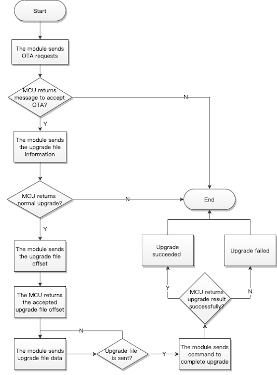
Initiate an update request (0xEA)
- The module initiates an update request to get the maximum length of one packet for serial transmission.
- For more information about the support for protocols, see Firmware types.
The module sends the following data.
| No. | Bytes | Field | Description |
|---|---|---|---|
| 0 1 |
2 | Header | 0x55 0xAA |
| 2 | 1 | Version number | 0x00 |
| 3 | 1 | Command (CMD) | 0xEA |
| 4 5 |
2 | Data length. | 0x00 0x02 |
| 6 to 7 | 2 | The maximum length of one packet Len1 |
See the information below. |
| 8 | 1 | CRC8 | Start from the header, add up all the bytes, and then divide the sum by 256 to get the remainder. |
Len1: The size of the largest packet that can be transmitted over the serial port, in the unit of bytes.
Example: 55 AA 00 EA 00 02 00 C8 B3
The MCU returns the following data.
| No. | Bytes | Field | Description |
|---|---|---|---|
| 0 1 |
2 | Header | 0x55 0xAA |
| 2 | 1 | Version number | 0x00 |
| 3 | 1 | Command (CMD) | 0xEA |
| 4 5 |
2 | Data length. | 0x00 0x06 |
| 6 to 11 | 6 | Data | See the following table. |
| 12 | 1 | CRC8 | Start from the header, add up all the bytes, and then divide the sum by 256 to get the remainder. |
Data format
| 1 | 2 to 4 | 5 to 6 |
|---|---|---|
| Flag | The MCU’s current firmware version (Version) |
The MCU-specified maximum length of one packet (Len2) |
Flag:0x00indicates the update is accepted.0x01indicates the update is rejected.Version: The current firmware version. For example,0x01 00 02representsv1.0.2.Len1: The module-specified maximum length of one packet.Len2: The MCU-specified maximum length of one packet. Iflen1is less thanlen2,len1prevails. Otherwise,len2prevails.
Example: 55 AA 00 EA 00 06 00 01 00 00 00 C8 B8
Send the update information (0xEB)
- The module sends the information about the firmware update to the MCU. The MCU determines whether to accept the update accordingly.
- For more information about the support for protocols, see Firmware types.
The module sends the following data.
| No. | Bytes | Field | Description |
|---|---|---|---|
| 0 1 |
2 | Header | 0x55 0xAA |
| 2 | 1 | Version number | 0x00 |
| 3 | 1 | Command (CMD) | 0xEB |
| 4 5 |
2 | Data length. | 0x00 0x23 |
| 6 to 40 | 35 | Data | See the following table. |
| 41 | 1 | CRC8 | Start from the header, add up all the bytes, and then divide the sum by 256 to get the remainder. |
Data format
| 8 bytes | 3 bytes | 16 bytes | 4 bytes | 4 bytes |
|---|---|---|---|---|
| PID | The firmware version. | The MD5 hash. | The file length. | CRC32 checksum. |
- PID: The PID of the MCU.
- Firmware version: The version of firmware to be installed. For example,
0x010002representsv1.0.2. - MD5 hash: The MD5 value of the firmware update.
- File length: The total length of the firmware update, in bytes.
- CRC32 checksum: The CRC32 value of the firmware update.
The MCU returns the following data.
| No. | Bytes | Field | Description |
|---|---|---|---|
| 0 1 |
2 | Header | 0x55 0xAA |
| 2 | 1 | Version number | 0x00 |
| 3 | 1 | Command (CMD) | 0xEB |
| 4 5 |
2 | Data length. | 0x00 0x19 |
| 6 to 30 | 25 | Data | See the following table. |
| 31 | 1 | CRC8 | Start from the header, add up all the bytes, and then divide the sum by 256 to get the remainder. |
Data format
| 1 byte | 4 bytes | 4 bytes | 16 bytes |
|---|---|---|---|
| STATE | The size of the update that has already been downloaded. | The CRC32 checksum of the update that has already been downloaded. | The MD5 hash value of the update that has already been downloaded. (Not used currently) |
STATE:
-
0x00: The update is performed as expected.
-
0x01: The received PID does not match the one written to the device.
-
0x02: The update version is earlier than or equal to the current version.
-
0x03: The update size exceeds the upper limit.
-
Other fields: Reserved
- The device returns information of the update that has been downloaded to continue downloading from where it was interrupted.
- After receiving the response message, the app will calculate the CRC32 checksum and compare it to the value received.
- If the two match exactly, the app will change the start offset to the received data length in the following transmission request. Otherwise, the start offset is 0, meaning downloading from scratch.
- The resumable transfer also follows the normal update process, starting from initiating an update request. If the module operates in any state rather than bound and connected, the MCU should reset the update status if any to start the following update procedure.
Request the update offset (0xEC)
For more information about the support for protocols, see Firmware types.
The module sends the following data.
| No. | Bytes | Field | Description |
|---|---|---|---|
| 0 1 |
2 | Header | 0x55 0xAA |
| 2 | 1 | Version number | 0x00 |
| 3 | 1 | Command (CMD) | 0xEC |
| 4 5 |
2 | Data length. | 0x00 0x04 |
| 6 to 9 | 4 | Offset | See the following table. |
| 10 | 1 | CRC8 | Start from the header, add up all the bytes, and then divide the sum by 256 to get the remainder. |
offset: indicate where to start downloading the update.
The MCU returns the following data.
| No. | Bytes | Field | Description |
|---|---|---|---|
| 0 1 |
2 | Header | 0x55 0xAA |
| 2 | 1 | Version number | 0x00 |
| 3 | 1 | Command (CMD) | 0xEC |
| 4 5 |
2 | Data length. | 0x00 0x04 |
| 6 to 9 | 4 | Offset | See the following table. |
| 10 | 1 | CRC8 | Start from the header, add up all the bytes, and then divide the sum by 256 to get the remainder. |
offset: the start offset specified by the MCU.
The start offset address specified by the MCU should take precedence over the one provided by the app. The MCU-specified offset is usually less than the one provided by the app.
Transmit the update (0xED)
For more information about the support for protocols, see Firmware types.
The module sends the following data.
| No. | Bytes | Field | Description |
|---|---|---|---|
| 0 1 |
2 | Header | 0x55 0xAA |
| 2 | 1 | Version number | 0x00 |
| 3 | 1 | Command (CMD) | 0xED |
| 4 5 |
2 | Data length (Len) | Upper 8 bits Lower 8 bits |
| 6 to 6+Len-1 | Len | Data | See the following table. |
| 6+Len | 1 | CRC8 | Start from the header, add up all the bytes, and then divide the sum by 256 to get the remainder. |
Data format
| 2 bytes | 2 bytes | 2 bytes | n byte(s) |
|---|---|---|---|
| Packet ID | The size of the current packet n |
The CRC16 checksum of the current packet | The payload of the current packet |
The packet ID starts from 0. The size of the current packet cannot exceed the specified maximum length of one packet.
The MCU returns the following data.
| No. | Bytes | Field | Description |
|---|---|---|---|
| 0 1 |
2 | Header | 0x55 0xAA |
| 2 | 1 | Version number | 0x00 |
| 3 | 1 | Command (CMD) | 0xED |
| 4 5 |
2 | Data length. | 0x00 0x01 |
| 6 | 1 | State | Return value |
| 7 | 1 | CRC8 | Start from the header, add up all the bytes, and then divide the sum by 256 to get the remainder. |
Return value
- 0x00: Success
- 0x01: Packet ID error.
- 0x02: The data length does not match the expected one.
- 0x03: CRC check failed.
- 0x04: Other error codes.
Request the update result (0xEE)
For more information about the support for protocols, see Firmware types.
The module sends the following data.
| No. | Bytes | Field | Description |
|---|---|---|---|
| 0 1 |
2 | Header | 0x55 0xAA |
| 2 | 1 | Version number | 0x00 |
| 3 | 1 | Command (CMD) | 0xEE |
| 4 5 |
2 | Data length. | 0x00 0x00 |
| 6 | 1 | CRC8 | Start from the header, add up all the bytes, and then divide the sum by 256 to get the remainder. |
The MCU returns the following data.
| No. | Bytes | Field | Description |
|---|---|---|---|
| 0 1 |
2 | Header | 0x55 0xAA |
| 2 | 1 | Version number | 0x00 |
| 3 | 1 | Command (CMD) | 0xEE |
| 4 5 |
2 | Data length. | 0x00 0x01 |
| 6 | 1 | State | Return value |
| 7 | 1 | CRC8 | Start from the header, add up all the bytes, and then divide the sum by 256 to get the remainder. |
Return value
- 0x00: Success
- 0x01: The total data length error.
- 0x02: The data length does not match the expected one.
- 0x03: Other error codes.
Production test
Radio frequency (RF) (0x0E)
-
Perform the received signal strength indicator (RSSI) test on modules to measure the RF performance.
-
Test tool:
- Bluetooth beacon (provided by Tuya)
- Purpose: Broadcast an identifier named
ty_mdev.
-
Test steps:
- Put the beacon around 0.5 meters away from the module.
- The MCU sends the RF test command to the module to initiate a test.
- The module will search for the designated identifier and return the RSSI. If the RSSI is greater than -70 dB, the RF performance is acceptable.
Some chip models such as BK3431Q and BK3432 do not support scanning for a designated beacon. You need to perform an RF test with a dongle.
- Test tool: A Bluetooth dongle. Purpose: Connect to the device under test and return the RSSI.
- Test steps:
- Put the dongle around 0.5 meters away from the module.
- The MCU sends the RF test command to the module to initiate a test.
- The dongle will connect to the module and return the RSSI. If the RSSI is greater than -70 dB, the RF performance is acceptable.
The module must be unbound and operate in the standard power mode.
The MCU sends the following data.
| No. | Bytes | Field | Description |
|---|---|---|---|
| 0 1 |
2 | Header | 0x55 0xAA |
| 2 | 1 | Version number | 0x00 |
| 3 | 1 | Command (CMD) | 0x0E |
| 4 5 |
2 | Data length. | 0x00 0x00 |
| 6 | 1 | CRC8 | Start from the header, add up all the bytes, and then divide the sum by 256 to get the remainder. |
The module returns the following data.
| No. | Bytes | Field | Description |
|---|---|---|---|
| 0 1 |
2 | Header | 0x55 0xAA |
| 2 | 1 | Version number | 0x00 |
| 3 | 1 | Command (CMD) | 0x0E |
| 4 5 |
2 | Data length (Len) | Upper 8 bits Lower 8 bits |
| 6 to 6+Len-1 | Len | Data | See the following table. |
| 6+Len | 1 | CRC8 | Start from the header, add up all the bytes, and then divide the sum by 256 to get the remainder. |
Data format
| Data | Description |
|---|---|
| {"ret":true,"rssi":"-55"} | The RSSI is -55 dB. |
| {"ret":false} | The designated signal is not found. |
Low power protocol
Low power mode
-
The module can operate in low power or standard power mode.
-
Standard power mode: The advertising interval is about 100 ms, which is not configurable currently. The two-way serial communication works.
-
Low power mode: The advertising interval is set by the MCU, defaulting to 1 second. If the interval is
0, advertising is turned off. For serial communication, the module only sends data to but does not receive data from the MCU.After BK3432 enters low power mode, it will proactively disconnect from Bluetooth and turn off advertising.
-
-
The MCU can pull down or up the low power pin on the module to make the module enter or exit the low power mode.
Lowpower_moudle_enableindicates whether you need to use the command0xE5to enable low power mode, as shown in the following table.Chip (product category) Lowpower_moudle_enable Moudle_wakeup_pin Wakeup_level Idle_level TLSR825x (all) Need TL_B5 High Low PHY6222 (all) Need P26 High Low BK3432 (all) Need P03 (configurable) High Low BK3431Q (locks) Not need P03 High Low nRF52832 (locks) Not need I/O11 Low High FR8016 (all) Need PA0 High Low After the module wakes up, a 100 ms time delay before serial communication is recommended. After waking up from deep sleep, Telink based modules need one second for startup.
-
To send data to the MCU, the module will wake up the MCU with the
wakeup_leveland then wait for a specified time before starting serial transmission. After data is sent, the wake-up pin will go back to theIdle_level, as shown in the following table.Chip (product category) Lowpower_moudle_enable Wakeup_mcu_pin Wakeup_level Idle_level TLSR825x (all) Need TL_D2 High Low PHY6222 (all) Need P31 High Low BK3432 (all) Need / / / BK3431Q (locks) Not need P10 High Low nRF52832 (locks) Not need I/O 14 Low High FR8016 (all) Need PA1 High Low For more information about the wake-up time, see Configure MCU wake-up (0xB0).
-
Each time the module is connected to the cloud, it will sync the internal clock with the app time. The accuracy of the module’s internal clock depends on the crystal oscillator. If your product requires accurate time, make sure to measure the accuracy of the internal clock. If you have any questions about measuring clock accuracy, submit a service ticket. The internal clock is reset after the power is turned off.
-
You can turn off the system timer in low power mode to reduce power consumption.
-
When the supply voltage is below the operating voltage, operations on the flash memory of the module might cause errors in firmware or user data. You can try the following methods to avoid this issue:
-
When the MCU detects a low battery level, it powers off the module or turns off advertising and makes the module enter sleep mode.
-
When the module detects a low battery level, it enters sleep mode.
The wake-up pin configuration varies depending on chipset platforms. Do not leave the wake-up pin on the MCU floating.
-
Enable low power feature (0xE5)
- If the
Lowpower_moudle_enableof your module isNeed, the MCU must send this command to the module to enable the low power feature. This way,Moudle_wakeup_pincan control the operation mode of the module. The configuration is stored in the nonvolatile memory. - This command is only used to enable the low power feature. The specific power mode depends on the voltage level of the low power pin on the module.
- For more information about the support for protocols, see Firmware types.
The MCU sends the following data.
| No. | Bytes | Field | Description |
|---|---|---|---|
| 0 1 |
2 | Header | 0x55 0xAA |
| 2 | 1 | Version number | 0x00 |
| 3 | 1 | Command (CMD) | 0xE5 |
| 4 5 |
2 | Data length. | 0x00 0x01 |
| 6 | 1 | Data | See the following table. |
| 7 | 1 | CRC8 | Start from the header, add up all the bytes, and then divide the sum by 256 to get the remainder. |
The valid values:
- 0x00: Disable low power feature.
- 0x01: Enable low power feature.
The module returns the following data.
| No. | Bytes | Field | Description |
|---|---|---|---|
| 0 1 |
2 | Header | 0x55 0xAA |
| 2 | 1 | Version number | 0x00 |
| 3 | 1 | Command (CMD) | 0xE5 |
| 4 5 |
2 | Data length. | 0x00 0x01 |
| 6 | 1 | State | Return value |
| 7 | 1 | CRC8 | Start from the header, add up all the bytes, and then divide the sum by 256 to get the remainder. |
Return value
- 0x00: Success
- Other values: Failure
Configure system timer (0xE4)
-
To further reduce the power consumption in sleep mode, you can use this command to turn off the system timer. If your MCU does not need timekeeping, you can also turn off the system timer. The configuration is stored in the nonvolatile memory.
-
For BK3431Q and TYBN1 modules, writing time data to flash memory is high power consumption and is turned off in sleep mode by default. The timekeeping function is still available because it uses less power. After you turn on the system timer, the time will be saved to the flash memory every one minute, which can fix the issue of clock reset after the module is restarted. The system timer is turned off by default.
With both the timer and advertising turned off, the Telink-based module can enter deep sleep with the power consumption reduced to 3 μA. After waking up, the module will restart.
The MCU sends the following data.
| No. | Bytes | Field | Description |
|---|---|---|---|
| 0 1 |
2 | Header | 0x55 0xAA |
| 2 | 1 | Version number | 0x00 |
| 3 | 1 | Command (CMD) | 0xE4 |
| 4 5 |
2 | Data length. | 0x00 0x01 |
| 6 | 1 | Data | See the following table. |
| 7 | 1 | CRC8 | Start from the header, add up all the bytes, and then divide the sum by 256 to get the remainder. |
The valid values:
- 0x00: Turn off system timer.
- 0x01: Turn on system timer.
The module returns the following data.
| No. | Bytes | Field | Description |
|---|---|---|---|
| 0 1 |
2 | Header | 0x55 0xAA |
| 2 | 1 | Version number | 0x00 |
| 3 | 1 | Command (CMD) | 0xE4 |
| 4 5 |
2 | Data length. | 0x00 0x01 |
| 6 | 1 | State | Return value |
| 7 | 1 | CRC8 | Start from the header, add up all the bytes, and then divide the sum by 256 to get the remainder. |
Return value
- 0x00: Success
- Other values: Failure
Configure the module wake-up pin (0xE3)
-
This command only applies to the BK3432 generic firmware.
-
You can use this command to set the custom pin to wake up the module from sleep. You can invoke this command after the UART initialization to configure the custom pin.
-
The configuration is stored in the nonvolatile memory.
-
For more information about the support for protocols, see Firmware types.
Since the module stops receiving serial data in the low power mode, the MCU must send this command within one second after the module is powered on, or before enabling the low power feature.
The MCU sends the following data.
| No. | Bytes | Field | Description |
|---|---|---|---|
| 0 1 |
2 | Header | 0x55 0xAA |
| 2 | 1 | Version number | 0x00 |
| 3 | 1 | Command (CMD) | 0xE3 |
| 4 5 |
2 | Data length. | 0x00 0x06 |
| 6 to 11 | 6 | Payload data CFG | See the following table. |
| 12 | 1 | CRC8 | Start from the header, add up all the bytes, and then divide the sum by 256 to get the remainder. |
Payload in CFG format
| 4 bytes | 1 byte | 1 byte |
|---|---|---|
| PIN_NUM | Reserved | Reserved |
PIN_NUM is a reserved field in big-endian format. It is not parsed so you can set it to 0xff or 0x00. If you have any questions about PIN_NUM, submit a service ticket.
Example:
-
Set the P03 on BK3432 as the wake-up pin. The
PIN_NUMfor P03 is0x03.55 AA 00 E3 00 06 00 00 00 03 00 00 EB -
Set the P11 on BK3432 as the wake-up pin. The
PIN_NUMfor P11 is0x11.55 AA 00 E3 00 06 00 00 00 11 00 00 F9The configurable pins on BK3432 are P02, P03, P04, P05, P10, P11, P12, P13, P34, P14, P35, P32. and P31. The
PIN_NUMfor Pxx on BK3432 is0xxx.
The module returns the following data.
| No. | Bytes | Field | Description |
|---|---|---|---|
| 0 1 |
2 | Header | 0x55 0xAA |
| 2 | 1 | Version number | 0x00 |
| 3 | 1 | Command (CMD) | 0xE3 |
| 4 5 |
2 | Data length. | 0x00 0x01 |
| 6 | 1 | State | Return value |
| 7 | 1 | CRC8 | Start from the header, add up all the bytes, and then divide the sum by 256 to get the remainder. |
Return value
- 0x00: Success
- Other values: Failure
Configure MCU wake-up time (0xB0)
-
You can use this command to set the time (t) used for waking up the MCU from sleep.
The module pulls up or down the wake-up pin for a specified time (t) before sending data to the MCU.
-
After modification, you must verify whether the specified time works. If not, you need to set a larger value.
-
You can invoke this command after the MCU receives the command 0x02. The configuration is stored in the volatile memory so it will reset to default when the module is turned off or restarted.
-
For more information about the support for protocols, see Firmware types.
The MCU sends the following data.
| No. | Bytes | Field | Description |
|---|---|---|---|
| 0 1 |
2 | Header | 0x55 0xAA |
| 2 | 1 | Version number | 0x00 |
| 3 | 1 | Command (CMD) | 0xB0 |
| 4 5 |
2 | Data length. | 0x00 0x01 |
| 6 | 1 | interval | See the information below. |
| 7 | 1 | CRC8 | Start from the header, add up all the bytes, and then divide the sum by 256 to get the remainder. |
interval indicates the unit of the wake-up time. The value ranges from 1 to 20, which means 10 ms to 200 ms.
Example:
55 aa 00 E2 00 01 00 E2, indicating advertising is turned off in low power mode.55 aa 00 E2 00 01 06 E8, indicating the advertising interval is 600 ms in low power mode.
The module returns the following data.
| No. | Bytes | Field | Description |
|---|---|---|---|
| 0 1 |
2 | Header | 0x55 0xAA |
| 2 | 1 | Version number | 0x00 |
| 3 | 1 | Command (CMD) | 0xB0 |
| 4 5 |
2 | Data length. | 0x00 0x01 |
| 6 | 1 | State | Return value |
| 7 | 1 | CRC8 | Start from the header, add up all the bytes, and then divide the sum by 256 to get the remainder. |
Return value
- 0x00: Success
- Other values: Failure
Extended features
This section describes how to implement the extended features such as dynamic data reporting, bulk data storage, file download, and weather services. You can implement these features as needed.
Flag-based status reporting (0xA4)
- You can use flags to indicate whether to report specific real-time data to the cloud or the app panel.
- For more information about the support for protocols, see Firmware types.
The MCU sends the following data.
| No. | Bytes | Field | Description |
|---|---|---|---|
| 0 1 |
2 | Header | 0x55 0xAA |
| 2 | 1 | Version number | 0x00 |
| 3 | 1 | Command (CMD) | 0xA4 |
| 4 5 |
2 | Data length (Len) | Upper 8 bits Lower 8 bits |
| 6 to 6+Len-1 | Len | Data | See the following table. |
| 6+Len | 1 | CRC8 | Start from the header, add up all the bytes, and then divide the sum by 256 to get the remainder. |
Data format
| 2 bytes | 1 byte | 1 byte | (Optional) 13 bytes | m byte(s) |
|---|---|---|---|---|
| Sequence number (SN) | Flag | Time_flag | Time_date | DP |
-
Sequence number (SN): two bytes in length, in big-endian (high byte first) format.
-
Flag:
- 0x00: Report data both to the cloud and the app panel.
- 0x01: Report data to the cloud but not to the app panel.
- 0x02: Report data to the app panel but not to the cloud.
- 0x03: Not report data.
-
Time_flag:- 0x00: Report data with the time data from the module.
- 0x01: Report data with the time data from the MCU.
- 0x02: Report data without including the time data.
-
Time_date: 13-digit Unix timestamp. This field is required whenTime_flagis set to0x01. -
DP data: the payload. For more information, see DP format.
For example, dynamic data is only reported to the app panel and without the time data.
55 AA 00 A4 00 0B 00 FF 02 02 65 00 00 03 13 23 66 B5
The module returns the following data.
| No. | Bytes | Field | Description |
|---|---|---|---|
| 0 1 |
2 | Header | 0x55 0xAA |
| 2 | 1 | Version number | 0x00 |
| 3 | 1 | Command (CMD) | 0xA4 |
| 4 5 |
2 | Data length. | 0x00 0x04 |
| 6 to 9 | 4 | Data | See the following table. |
| 10 | 1 | CRC8 | Start from the header, add up all the bytes, and then divide the sum by 256 to get the remainder. |
Data format
| 2 bytes | 1 byte | 1 byte |
|---|---|---|
| Sequence number (SN) | Flag | State |
- Sequence number (SN): This value is from the reported data from the MCU.
- Flag: This value is from the reported data from the MCU.
- State:
0x00indicates success. All other values indicate failure.
Bulk data storage (0xB5)
The MCU sends the following data.
| No. | Bytes | Field | Description |
|---|---|---|---|
| 0 1 |
2 | Header | 0x55 0xAA |
| 2 | 1 | Version number | 0x00 |
| 3 | 1 | Command (CMD) | 0xB5 |
| 4 5 |
2 | Data length (Len) | Upper 8 bits Lower 8 bits |
| 6 | 1 | SubCmd | See the information below. |
| 7 to 7+Len-1 | Len | Data | See the information below. |
| 7+Len | 1 | CRC8 | Start from the header, add up all the bytes, and then divide the sum by 256 to get the remainder. |
SubCmd (Subcommand):
- 0x00: Data storage
- 0x01: Storage configuration
The format of the Data field varies depending on subcommands. The module parses data according to the SubCmd and the Data format.
-
When
SubCmdis0x00, the format of theDatafield is as follows:1 to 3 4 5 to x x x+1 x+2 to x+3 x+4 and greater … n n+1 n+1 to n+2 n+3 and greater Res TYPE Time_Str dp1_id dp1_type dp1_len dp1_data … dpN_id dpN_type dpN_len dpN_data Res: 3-byte reserved field. Set it to0x00.TYPE The time data for use 0x01 Format 1: Report status with the time data from the Bluetooth module 0x03 Format 3: Report status with the time data from the MCU Time_Str:- 13-digit Unix timestamp.
- This field is required only when
TYPEis0x03.
-
When
SubCmdis0x01, the format of theDatafield is as follows:CFG (1 byte) Description 0x00 Store small data that can contain two DPs of value type. dplen1+3+[dplen2+3]+[dplen_n+3]≤ 170x01 Store medium data that can contain six DPs of value type. dplen1+3+[dplen2+3]+[dplen_n+3]≤ 49.0x02 The default configuration dplen1+3+[dplen2+3]+[dplen_n+3]≤ 113When CFG is changed, the module will clear the bulk data storage.
The module returns the following data.
| No. | Bytes | Field | Description |
|---|---|---|---|
| 0 1 |
2 | Header | 0x55 0xAA |
| 2 | 1 | Version number | 0x00 |
| 3 | 1 | Command (CMD) | 0xB5 |
| 4 5 |
2 | Data length. | 0x00 0x01 |
| 6 | 1 | SubCmd | See the following table. |
| 7 to 7+Len-1 | Len | Data | See the information below. |
| 7+Len | 1 | CRC8 | Start from the header, add up all the bytes, and then divide the sum by 256 to get the remainder. |
SubCmd (Subcommand):
- 0x00: Data storage
- 0x01: Storage configuration
The format of the Data field varies depending on subcommands. The module parses data according to the SubCmd and the Data format.
-
When
SubCmdis0x00, the format of theDatafield is as follows:STATE (1 byte):
- 0x00: Success
- 0x01: Length error
- 0x02: Type error
- 0x03: Invalid DP data format
- 0x04: Storage error
- Other values: Failure
-
When
SubCmdis0x01, the format of theDatafield is as follows:1 2 3 to 4 STATE MAX_SIZE TOTAL_NUM - STATE:
- 0x00: Success
- Other values: Failure
MAX_SIZE: The maximum length of a piece of data.TOTAL_NUM: The total number of pieces of data that can be stored.
- STATE:
Example:
- To set small data storage, the MCU sends
55 aa 00 b5 00 02 01 00 B7. - To set medium data storage, the MCU sends
55 aa 00 b5 00 02 01 01 B8. - To set general data storage, the MCU sends
55 aa 00 b5 00 02 01 02 B9. - To store a piece of data, the MCU sends
55 AA 00 B5 00 12 00 01 01 02 00 04 00 00 01 04 02 02 00 04 00 00 00 DB.
Get weather data (0xB6)
- The MCU can use this command to request the specified weather data in a specific location from the mobile app.
- For more information, see the Appendix.
The MCU sends the following data.
| No. | Bytes | Field | Description |
|---|---|---|---|
| 0 1 |
2 | Header | 0x55 0xAA |
| 2 | 1 | Version number | 0x00 |
| 3 | 1 | Command (CMD) | 0xB6 |
| 4 5 |
2 | Data length (Len) | Upper 8 bits Lower 8 bits |
| 6 to 6+Len-1 | Len | Data | See the information below. |
| 6+Len | 1 | CRC8 | Start from the header, add up all the bytes, and then divide the sum by 256 to get the remainder. |
Data description:
| Location | Weather parameter | Number of forecast days |
|---|---|---|
| 1 byte | 4 bytes | 1 byte |
-
Location:
- 0x01: The location where the device is paired.
- 0x02: The location where the mobile phone is.
-
Weather parameter
(1 << 0), /**< temperature. */ (1 << 1), /**< high temperature. */ (1 << 2), /**< low temperature. */ (1 << 3), /**< humidity. */ (1 << 4), /**< weather condition. */ (1 << 5), /**< pressure. */ (1 << 6), /**< sensible temperature. */ (1 << 7), /**< uvi. */ (1 << 8), /**< sunrise. */ (1 << 9), /**< sunset. */ (1 << 10), /**< unix time, Use with sunrise and sunset. */ (1 << 11), /**< local time, Use with sunrise and sunset. */ (1 << 12), /**< wind speed. */ (1 << 13), /**< wind direction. */ (1 << 14), /**< wind speed scale/level. */ (1 << 15), /**< aqi. */ (1 << 16), /**< tips. */ (1 << 17), /**< Detailed AQI status and national ranking. */ (1 << 18), /**< pm10. */ (1 << 19), /**< pm2.5. */ (1 << 20), /**< o3. */ (1 << 21), /**< no2. */ (1 << 22), /**< co. */ (1 << 23), /**< so2. */ (1 << 24), /**< weather condition mapping id. */ -
Number of forecast days: Specifies the number of days for which the server returns forecast data. The valid value ranges from
1to7(1indicates today). For more information, see the Appendix.
The module returns the following data.
| No. | Bytes | Field | Description |
|---|---|---|---|
| 0 1 |
2 | Header | 0x55 0xAA |
| 2 | 1 | Version number | 0x00 |
| 3 | 1 | Command (CMD) | 0xB6 |
| 4 5 |
2 | Data length (Len) | Upper 8 bits Lower 8 bits |
| 6 to 6+Len-1 | Len | Data | See the information below. |
| 6+Len | 1 | CRC8 | Start from the header, add up all the bytes, and then divide the sum by 256 to get the remainder. |
Data description: status (1 byte) + weather_values (0 bytes or Len-1 bytes).
-
Status:
0x00: Success
0x01: Parameter error
0x02: Request failed
0x03: Request timeout
0x04: Repeated request
0x05: Status error
-
Weather_values: The value of weather, which is valid whenstatusis0x00. For more information about the data format, see the following table.Day Weather parameter (little-endian) Data type Data length Data … 1 byte 4 bytes 1 byte 1 byte x byte(s) …
Data type:
0x00: Integer0x01: String
Example:
The MCU sends the following data to the module:
55 AA 00 B6 00 06 01 00 00 00 0F 01 CC
The module returns the following data to the MCU:
55 AA 00 B6 00 2D 00 01 01 00 00 00 00 04 00 00 00 21 01 02 00 00 00 00 04 00 00 00 24 01 04 00 00 00 00 04 00 00 00 1C 01 08 00 00 00 00 04 00 00 00 44 AA
Triggered pairing mode (0xBC)
- The advertising state of an unbound Bluetooth device is called pairing state. This command only applies to unbound Bluetooth devices.
- When you disable the triggered pairing mode, the device resumes the default pairing mode (advertising is always on).
- There are two scenarios for devices with the triggered pairing mode enabled.
- If the device is not bound, it will not start Bluetooth advertising automatically when powered on.
- If the device has been bound, it will not start Bluetooth advertising automatically after unbinding.
- The triggered pairing mode restricts Bluetooth advertising on unbound devices. However, this mode does not apply once a device is paired.
- The triggered pairing mode supports power-off memory, but the advertising duration is not retained after power off.
The MCU sends the following data.
| No. | Bytes | Field | Description |
|---|---|---|---|
| 0 1 |
2 | Header | 0x55 0xAA |
| 2 | 1 | Version number | 0x00 |
| 3 | 1 | Command (CMD) | 0xBC |
| 4 5 |
2 | Data length (Len) | Upper 8 bits Lower 8 bits |
| 6 to 6+Len-1 | Len | Data | See the description below. |
| 6+Len | 1 | CRC8 | Start from the header, add up all the bytes, and then divide the sum by 256 to get the remainder. |
Data description:
ENABLE |
ON_OFF |
TIME |
|---|---|---|
| 1 byte | 1 byte | 2 bytes |
ENABLE:0x00: Disable the triggered pairing mode, using the default pairing mode. When you set this field to0x00, the module does not parse the subsequent fields.0x01: Enable the triggered pairing mode.
ON_OFF:0x00: Exit pairing mode immediately. When you set this field to0x00, the module does not parse the subsequent fields.0x01: Enter pairing mode immediately.
TIME: Timeout for triggering pairing mode, in seconds, ranging from 10 to 600.
The module returns the following data.
| No. | Bytes | Field | Description |
|---|---|---|---|
| 0 1 |
2 | Header | 0x55 0xAA |
| 2 | 1 | Version number | 0x00 |
| 3 | 1 | Command (CMD) | 0xBC |
| 4 5 |
2 | Data length (Len) | Upper 8 bits Lower 8 bits |
| 6 to 6+Len-1 | Len | Status | See the description below. |
| 6+Len | 1 | CRC8 | Start from the header, add up all the bytes, and then divide the sum by 256 to get the remainder. |
Status:
0x00: Success0x01: Parameter error0x02: Request failed0x03: Status error (The device is not in the unbound state.)
Bluetooth remote control configuration (0xC100)
This feature allows the user to control a device using a physical Bluetooth remote control. It is disabled by default.
- If you choose the module self-processing of Bluetooth remotes pairing request for the
CFGfield, the module will allow pairing with a Bluetooth remote control within 30 seconds of powering on. - If you choose the MCU and module co-processing of Bluetooth remotes pairing request for the
CFGfield, the MCU can accept or reject the pairing request. - Up to five devices can be paired with the Bluetooth remote control. Otherwise, pairing will fail.
- With the Bluetooth remote control enabled, the module will not enter the low power mode. You need to call the command to disable Bluetooth remote control before the module enters the low power mode and enable the feature after the module exits the low power mode.
- The configuration is stored in the nonvolatile memory.
The MCU sends the following data.
| No. | Bytes | Field | Description |
|---|---|---|---|
| 0 1 |
2 | Header | 0x55 0xAA |
| 2 | 1 | Version number | 0x00 |
| 3 | 1 | Command (CMD) | 0xC1 |
| 4 5 |
2 | Data length | 0x00 0x02 |
| 6 | 1 | Subcommand | 0x00 |
| 78 |
2 | Data |
|
| 9 | 1 | CRC8 | Start from the header, add up all the bytes, and then divide the sum by 256 to get the remainder. |
Example: 55 AA 00 C1 00 03 00 01 05 C9, meaning to enable the Bluetooth remote control.
The module returns the following data.
| No. | Bytes | Field | Description |
|---|---|---|---|
| 0 1 |
2 | Header | 0x55 0xAA |
| 2 | 1 | Version number | 0x00 |
| 3 | 1 | Command (CMD) | 0xC1 |
| 4 5 |
2 | Data length | 0x00 0x02 |
| 6 | 1 | Subcommand | 0x00 |
| 7 | 1 | Data |
|
| 8 | 1 | CRC8 | Start from the header, add up all the bytes, and then divide the sum by 256 to get the remainder. |
Bluetooth remote control data notification (0xC101)
- This feature applies when you enable the Bluetooth remote control.
- For more information about the control commands, see Appendix 3.
The module sends the following data.
| No. | Bytes | Field | Description |
|---|---|---|---|
| 0 1 |
2 | Header | 0x55 0xAA |
| 2 | 1 | Version number | 0x00 |
| 3 | 1 | Command (CMD) | 0xC1 |
| 4 5 |
2 | Data length | 0x00 0x06 |
| 6 | 1 | Subcommand | 0x01 |
| Data |
|
||
| 13 | 1 | CRC8 | Start from the header, add up all the bytes, and then divide the sum by 256 to get the remainder. |
The MCU returns the following data.
| No. | Bytes | Field | Description |
|---|---|---|---|
| 0 1 |
2 | Header | 0x55 0xAA |
| 2 | 1 | Version number | 0x00 |
| 3 | 1 | Command (CMD) | 0xC1 |
| 4 5 |
2 | Data length | 0x00 0x01 |
| 6 | 1 | Subcommand | 0x01 |
| 7 | 1 | CRC8 | Start from the header, add up all the bytes, and then divide the sum by 256 to get the remainder. |
Bluetooth remote control binding notification (0xC102)
This feature applies when you enable the Bluetooth remote control.
The module sends the following data.
| No. | Bytes | Field | Description |
|---|---|---|---|
| 0 1 |
2 | Header | 0x55 0xAA |
| 2 | 1 | Version number | 0x00 |
| 3 | 1 | Command (CMD) | 0xC1 |
| 4 5 |
2 | Data length | 0x00 0x03 |
| 6 | 1 | Subcommand | 0x02 |
| 7 8 |
2 | Data |
|
| 9 | 1 | CRC8 | Start from the header, add up all the bytes, and then divide the sum by 256 to get the remainder. |
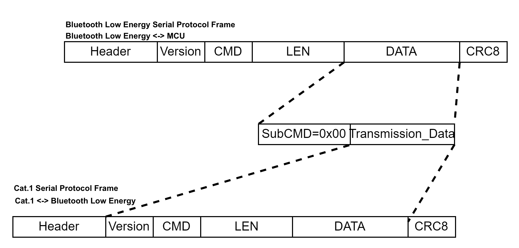
Combo module protocol
The following table lists the frame format for Bluetooth and network module combo protocol.
| No. | Bytes | Field | Description |
|---|---|---|---|
| 0 1 |
2 | Header | 0x55 0xAA |
| 2 | 1 | Version number | 0x00 |
| 3 | 1 | Command (CMD) | 0xC0 |
| 4 5 |
2 | Data length (Len) | Upper 8 bits Lower 8 bits |
| 6 to 6+Len-1 | 1 | SubCmd | The subcommand. |
| Len-1 | Data | The subcommand data. | |
| 6+Len | 1 | CRC8 | Start from the header, add up all the bytes, and then divide the sum by 256 to get the remainder. |
Cross-protocol data pass-through (0xC000)
The MCU can use this command to access the network module (such as the LTE Cat.1 module) as instructed in LTE Cat.1 Serial Port Protocol to get information, such as positioning information.
Frame format:
| No. | Bytes | Field | Description |
|---|---|---|---|
| 0 1 |
2 | Header | 0x55 0xAA |
| 2 | 1 | Version number | 0x00 |
| 3 | 1 | Command (CMD) | 0xC0 |
| 4 5 |
2 | Data length (Len) | Upper 8 bits Lower 8 bits |
| 6 to 6+Len-1 | 1 | SubCmd | 0x00 |
| Len-1 | DATA | Includes the version number, command, data length, and data fields for the pass-through protocol. | |
| 6+Len | 1 | CRC8 | Start from the header, add up all the bytes, and then divide the sum by 256 to get the remainder. |
Power control of extended module (0xC001)
- This command should be used based on the specific hardware design.
- See the Bluetooth module datasheet or hardware design for details on the pin used for power control of the extended module.
The MCU sends the following data.
| No. | Bytes | Field | Description |
|---|---|---|---|
| 0 1 |
2 | Header | 0x55 0xAA |
| 2 | 1 | Version number | 0x00 |
| 3 | 1 | Command (CMD) | 0xC0 |
| 4 5 |
2 | Data length (Len) | Upper 8 bits Lower 8 bits |
| 6 to 6+Len-1 | 1 | SubCmd | 0x01 |
| Len-1 | DATA | See the following table. | |
| 6+Len | 1 | CRC8 | Start from the header, add up all the bytes, and then divide the sum by 256 to get the remainder. |
Data format:
| 1 byte | 1 byte |
|---|---|
op_type |
op_object |
-
op_type:0x01: Notify. When the MCU bypasses the Bluetooth module and directly controls the power on/off of the extended module, it notifies the Bluetooth module to update the power status.0x02: Control. The MCU controls the power on/off of the extended module through the specific pin on the Bluetooth module.0x03: Read. The MCU reads the power status of the extended module.
-
op_object:bit0: The pin to control the power of the extended module 1 (cellular module).0indicates power off and1indicates power on.bit1: The pin to control the power of the extended module 2 (GPS module).0indicates power off and1indicates power on.- All other bits are reserved.
The module returns the following data.
| No. | Bytes | Field | Description |
|---|---|---|---|
| 0 1 |
2 | Header | 0x55 0xAA |
| 2 | 1 | Version number | 0x00 |
| 3 | 1 | Command (CMD) | 0xC0 |
| 4 5 |
2 | Data length (Len) | Upper 8 bits Lower 8 bits |
| 6 to 6+Len-1 | 1 | SubCmd | 0x01 |
| Len-1 | DATA | See the following table. | |
| 6+Len | 1 | CRC8 | Start from the header, add up all the bytes, and then divide the sum by 256 to get the remainder. |
Data format:
| 1 byte | 1 byte | 1 byte |
|---|---|---|
op_type |
op_object |
status |
Status:
- 0x00: Success
- Other values: Failure
Query the extended module’s presence (0xC002)
- When the cellular module is inserted or removed, the Bluetooth module notifies the MCU of this event. Alternatively, the MCU can proactively request the presence of the extended module.
- When the cellular module is removed, the MCU should power off the extended module before entering low power mode to reduce power consumption.
The MCU sends the following data.
| No. | Bytes | Field | Description |
|---|---|---|---|
| 0 1 |
2 | Header | 0x55 0xAA |
| 2 | 1 | Version number | 0x00 |
| 3 | 1 | Command (CMD) | 0xC0 |
| 4 5 |
2 | Data length (Len) | Upper 8 bits Lower 8 bits |
| 6 | 1 | SubCmd | 0x02 |
| 7 | 1 | CRC8 | Start from the header, add up all the bytes, and then divide the sum by 256 to get the remainder. |
The module returns the following data.
| No. | Bytes | Field | Description |
|---|---|---|---|
| 0 1 |
2 | Header | 0x55 0xAA |
| 2 | 1 | Version number | 0x00 |
| 3 | 1 | Command (CMD) | 0xC0 |
| 4 5 |
2 | Data length (Len) | Upper 8 bits Lower 8 bits |
| 6 | 1 | SubCmd | 0x02 |
| 7 | 1 | Status |
|
| 8 | 1 | CRC8 | Start from the header, add up all the bytes, and then divide the sum by 256 to get the remainder. |
Configuration of extended module (0xC003)
- Currently, only Access Point Name (APN) configuration is supported.
- It is recommended to configure after the command
0x01but before the command0x02. If you invoke the command in other places, the module will check for configuration consistency and reset the extended module if a mismatch occurs.
The MCU sends the following data.
| No. | Bytes | Field | Description |
|---|---|---|---|
| 0 1 |
2 | Header | 0x55 0xAA |
| 2 | 1 | Version number | 0x00 |
| 3 | 1 | Command (CMD) | 0xC0 |
| 4 5 |
2 | Data length (Len) | Upper 8 bits Lower 8 bits |
| 6 | 1 | SubCmd | 0x03 |
| Configurations | {"apn":"xxx"} | ||
| 7 | 1 | CRC8 | Start from the header, add up all the bytes, and then divide the sum by 256 to get the remainder. |
Example:
55 AA 00 C0 00 10 03 7B 22 61 70 6E 22 3A 22 63 6E 69 6F 74 22 7D EB ({"apn","cniot"}})
55 AA 00 C0 00 0B 03 7B 22 61 70 6E 22 3A 22 22 7D C6 (Clear the configuration)
The module returns the following data.
| No. | Bytes | Field | Description |
|---|---|---|---|
| 0 1 |
2 | Header | 0x55 0xAA |
| 2 | 1 | Version number | 0x00 |
| 3 | 1 | Command (CMD) | 0xC0 |
| 4 5 |
2 | Data length (Len) | Upper 8 bits Lower 8 bits |
| 6 | 1 | SubCmd | 0x03 |
| 7 | 1 | Status |
|
| 8 | 1 | CRC8 | Start from the header, add up all the bytes, and then divide the sum by 256 to get the remainder. |
Extended MCU protocol for accessories
This protocol extends the capabilities of the MCU to the non-smart accessories.
Sync accessory status (0xC200)
- The connection status of a non-smart accessory depends on the Bluetooth status of the main device. When Bluetooth is disconnected, the accessory is offline.
- The MCU detects the presence of an accessory and notifies the Bluetooth module of the accessory status through this command for the module to update the status.
The MCU sends the following data.
| No. | Bytes | Field | Description |
|---|---|---|---|
| 0 1 |
2 | Header | 0x55 0xAA |
| 2 | 1 | Version number | 0x00 |
| 3 | 1 | Command (CMD) | 0xC2 |
| 4 5 |
2 | Data length (Len) | 0x00 0x02 |
| 6 to 6+Len-1 | 1 | SubCmd | 0x00 |
| 1 | Status |
|
|
| 6+Len | 1 | CRC8 | Start from the header, add up all the bytes, and then divide the sum by 256 to get the remainder. |
The module returns the following data.
| No. | Bytes | Field | Description |
|---|---|---|---|
| 0 1 |
2 | Header | 0x55 0xAA |
| 2 | 1 | Version number | 0x00 |
| 3 | 1 | Command (CMD) | 0xC2 |
| 4 5 |
2 | Data length (Len) | 0x00 0x02 |
| 6 | 1 | SubCmd | 0x00 |
| 7 | 1 | Status |
|
| 8 | 1 | CRC8 | Start from the header, add up all the bytes, and then divide the sum by 256 to get the remainder. |
Bluetooth-specific protocol
Disconnect Bluetooth proactively (0xE7)
The MCU sends this command to the module to disconnect the Bluetooth connection and enter the advertising state.
The MCU sends the following data.
| No. | Bytes | Field | Description |
|---|---|---|---|
| 0 1 |
2 | Header | 0x55 0xAA |
| 2 | 1 | Version number | 0x00 |
| 3 | 1 | Command (CMD) | 0xE7 |
| 4 5 |
2 | Data length. | 0x00 0x00 |
| 6 | 1 | CRC8 | Start from the header, add up all the bytes, and then divide the sum by 256 to get the remainder. |
The module returns the following data.
| No. | Bytes | Field | Description |
|---|---|---|---|
| 0 1 |
2 | Header | 0x55 0xAA |
| 2 | 1 | Version number | 0x00 |
| 3 | 1 | Command (CMD) | 0xE7 |
| 4 5 |
2 | Data length. | 0x00 0x01 |
| 6 | 1 | State | Return value |
| 7 | 1 | CRC8 | Start from the header, add up all the bytes, and then divide the sum by 256 to get the remainder. |
Return value
- 0x00: Success
- Other values: Failure
Advertising enablement (0xA3)
-
In standard power mode, the advertising interval is 100 ms. In low power mode, the advertising interval can range from 0 to 2,000 ms and defaults to 1,000 ms. 0 means turning off advertising. The module will be paired when the app receives the advertisement. This command allows the MCU to enable or disable advertising so that the MCU can determine when to perform pairing.
-
You need to invoke this command to set the advertising enablement after the UART initialization. The enablement state is stored in the flash memory. The MCU should enable advertising when performing pairing and disable it in other cases.
-
The advertising is enabled by default. After you disable advertising through this command, the module will not advertise both in standard and low power mode.
-
Disabling advertising will stop ongoing advertising immediately.
-
When advertising is enabled, the module will start advertising immediately.
-
For more information about the support for protocols, see Firmware types.
This command works for both the standard and the low power mode. Modification of advertising interval only works for the low power mode. Therefore, to modify the time for performing pairing, you must use the advertising enablement command.
The MCU sends the following data.
| No. | Bytes | Field | Description |
|---|---|---|---|
| 0 1 |
2 | Header | 0x55 0xAA |
| 2 | 1 | Version number | 0x00 |
| 3 | 1 | Command (CMD) | 0xA3 |
| 4 5 |
2 | Data length. | 0x00 0x01 |
| 6 | 1 | Data | See the following table. |
| 7 | 1 | CRC8 | Start from the header, add up all the bytes, and then divide the sum by 256 to get the remainder. |
The valid values:
- 0x00: Disable advertising.
- 0x01: Enable advertising.
The module returns the following data.
| No. | Bytes | Field | Description |
|---|---|---|---|
| 0 1 |
2 | Header | 0x55 0xAA |
| 2 | 1 | Version number | 0x00 |
| 3 | 1 | Command (CMD) | 0xA3 |
| 4 5 |
2 | Data length. | 0x00 0x01 |
| 6 | 1 | State | Return value |
| 7 | 1 | CRC8 | Start from the header, add up all the bytes, and then divide the sum by 256 to get the remainder. |
Return value
- 0x00: Success
- Other values: Failure
Request getting online (0xA5)
- This command is used to connect to the gateway when needed.
- The module will advertise for 30 seconds after the MCU invokes this command.
- After receiving the flagged advertisement, the Bluetooth central device will connect to the module.
- After the module is online, the MCU can report the status to the module.
- Typically, the MCU uses the command
0xE0to report record-type data. If the module is bound but not connected, the MCU will use this command to request to get the module online. Then, after getting online, the module will release the stranded data reported through0xE0. - To report the real-time data, try the following two methods:
- The MCU invokes this command and waits for an online notification. The module will notify the MCU of its status after getting online.
- The MCU can report real-time data in
0x02format through the command0xE0. After getting online, the module will send the stranded data to the app. This method is not recommended.
- For more information about the support for protocols, see Firmware types.
The MCU sends the following data.
| No. | Bytes | Field | Description |
|---|---|---|---|
| 0 1 |
2 | Header | 0x55 0xAA |
| 2 | 1 | Version number | 0x00 |
| 3 | 1 | Command (CMD) | 0xA5 |
| 4 5 |
2 | Data length. | 0x00 0x00 |
| 6 | 1 | CRC8 | Start from the header, add up all the bytes, and then divide the sum by 256 to get the remainder. |
The module returns the following data.
| No. | Bytes | Field | Description |
|---|---|---|---|
| 0 1 |
2 | Header | 0x55 0xAA |
| 2 | 1 | Version number | 0x00 |
| 3 | 1 | Command (CMD) | 0xA5 |
| 4 5 |
2 | Data length. | 0x00 0x01 |
| 6 | 1 | State | Return value |
| 7 | 1 | CRC8 | Start from the header, add up all the bytes, and then divide the sum by 256 to get the remainder. |
Return value
- 0x00: Success
- Other values: Failure
Modify advertising interval in low power mode (0xE2)
-
This command does not apply to the BK3432 generic firmware for shared devices.
-
To further reduce the power consumption in sleep mode, you can use this command to modify the advertising interval. The configuration is stored in the nonvolatile memory. If the interval is set to 0, advertising is turned off. The configuration is stored in the nonvolatile memory.
The advertisement interval defaults to one second in the low power mode. A long interval means taking more time to connect to a mobile phone. If the phone has poor radio performance, the Bluetooth connection attempt might fail.
-
For more information about the support for protocols, see Firmware types.
The MCU sends the following data.
| No. | Bytes | Field | Description |
|---|---|---|---|
| 0 1 |
2 | Header | 0x55 0xAA |
| 2 | 1 | Version number | 0x00 |
| 3 | 1 | Command (CMD) | 0xE2 |
| 4 5 |
2 | Data length. | 0x00 0x01 |
| 6 | 1 | Adv_interval | See the following table. |
| 7 | 1 | CRC8 | Start from the header, add up all the bytes, and then divide the sum by 256 to get the remainder. |
Adv_interval: The valid values range from 0 to 20 in units of 100 ms. If the interval is set to 0, advertising is turned off.
Example:
55 aa 00 E2 00 01 00 E2, indicating advertising is turned off in low power mode.55 aa 00 E2 00 01 06 E8, indicating the advertising interval is 600 ms in low power mode.
The module returns the following data.
| No. | Bytes | Field | Description |
|---|---|---|---|
| 0 1 |
2 | Header | 0x55 0xAA |
| 2 | 1 | Version number | 0x00 |
| 3 | 1 | Command (CMD) | 0xE2 |
| 4 5 |
2 | Data length. | 0x00 0x01 |
| 6 | 1 | State | Return value |
| 7 | 1 | CRC8 | Start from the header, add up all the bytes, and then divide the sum by 256 to get the remainder. |
Return value
- 0x00: Success
- Other values: Failure
Set the connection interval (0xB1)
- If the module is in the bound and connected state when receiving this command, it will send a request for updating the connection parameters to the central. Otherwise, it only saves the connection parameters for later connections. However, if the module is performing an OTA update, it will not request to update the connection parameters to the central but save it.
- After getting online, the module will release the stranded data if any, and then update the connection parameters.
- The configuration is stored in the nonvolatile memory.
- For more information about the support for protocols, see Firmware types.
The MCU sends the following data.
| No. | Bytes | Field | Description |
|---|---|---|---|
| 0 1 |
2 | Header | 0x55 0xAA |
| 2 | 1 | Version number | 0x00 |
| 3 | 1 | Command (CMD) | 0xB1 |
| 4 5 |
2 | Data length. | 0x00 0x0B |
| 6 to 16 | 11 | CFG | See the information below. |
| 17 | 1 | CRC8 | Start from the header, add up all the bytes, and then divide the sum by 256 to get the remainder. |
CFG format:
| 1 byte | 1 byte | 1 byte | 2 bytes | 2 bytes | 2 bytes | 2 bytes |
|---|---|---|---|---|---|---|
| cfg_type | cfg_ack | mode | min_interval | max_interval | latency | timeout |
-
cfg_type: The configuration method.- 0x00: Configuration by mode. Choose the connection parameters with the
modefield. Ifmin_interval,min_interval,latency, andtimeoutdo not work, you can use this method. - 0x01: Custom configuration. Set the interval with the
min_intervalandtimeout. This method applies to Bluetooth devices.
- 0x00: Configuration by mode. Choose the connection parameters with the
-
cfg_ack: Acknowledgement (ACK) response.- 0x00: Not configure the ACK response.
- 0x01: Configure the ACK response. The connection parameters are assigned by the central. If the parameters fail to be updated, the configuration should respond to the failure. After successful updating, the module will send the connection parameters for use to the MCU.
-
mode:- 0x00: Fast-speed mode. Provide fast interaction but use more battery. This mode applies to products that prioritize fast response by compromising the power consumption.
- 0x01: Balanced mode. Provide moderate response time and power consumption.
- 0x02: Low-speed mode. Provide slow response time but use less battery. This mode applies to products that prioritize power consumption with less interaction with the app, such as sensors.
-
min_interval: The minimal connection interval, in the unit of 1.25 ms. For more information, see the connection interval specified in the Generic Access Profile (GAP). -
max_interval: The maximum connection interval, in the unit of 1.25 ms. For more information, see the connection interval specified in the Generic Access Profile (GAP). -
latency: Peripheral latency. This parameter gives the peripheral device the option of skipping a number of connection events. For more information, see the connection interval specified in the Generic Access Profile (GAP). -
timeout: The maximum amount of time between two successful connection events, in the unit of 10 ms. For more information, see the connection interval specified in the Generic Access Profile (GAP).The field greater than two bytes is transmitted in big-endian format. You can set
cfg_typeandcfg_ackto0x00if these two parameters are not required for you.
The module returns the following data.
| No. | Bytes | Field | Description |
|---|---|---|---|
| 0 1 |
2 | Header | 0x55 0xAA |
| 2 | 1 | Version number | 0x00 |
| 3 | 1 | Command (CMD) | 0xB1 |
| 4 5 |
2 | Data length. | 0x00 0x09 |
| 6 to 14 | 1 | State | Return value |
| 15 | 1 | CRC8 | Start from the header, add up all the bytes, and then divide the sum by 256 to get the remainder. |
State
| 1 byte | 2 bytes | 2 bytes | 2 bytes | 2 bytes |
|---|---|---|---|---|
| result | min_interval | max_interval | latency | timeout |
result:
-
0x00: The module receives the new connection parameters and will request a parameter update with the central.
min_interval,max_interval,latency, andtimeoutindicate the parameters of the target connection. -
0x01: The connection parameters are updated successfully.
min_interval,max_interval,latency, andtimeoutindicate the parameters of the actual connection. -
0x02: Updating the connection parameters failed.
min_interval,max_interval,latency, andtimeoutindicate the parameters of the target connection. -
0x03: Illegal state. Generally, the module is not in the bound and connected state.
-
0x06: Invalid parameter.
-
Other values: Failure
If
cfg_ackis set to0x01, the module syncs the current connection parameters to the MCU only after receiving the success ACK message. The result0x01or0x02can be returned only whencfg_ackis set to0x01. Otherwise, the module will not return the operation result to the MCU.
Example:
-
Set to low-speed mode:
- The MCU sends:
55 AA 00 B1 00 0B 00 00 02 00 00 00 00 00 00 00 00 BD - The module returns:
55 AA 00 B1 00 09 00 01 90 01 A0 00 00 01 90 7C
- The MCU sends:
-
Set to balanced mode:
- The MCU sends:
55 AA 00 B1 00 0B 00 00 01 00 00 00 00 00 00 00 00 BC - The module returns:
55 AA 00 B1 00 09 00 00 90 00 A0 00 00 01 90 7A
- The MCU sends:
-
Set to fast-speed mode:
- The MCU sends:
55 AA 00 B1 00 0B 00 00 00 00 00 00 00 00 00 00 00 BB - The module returns:
55 AA 00 B1 00 09 00 00 32 00 3C 00 00 01 90 B8
- The MCU sends:
-
Set to custom parameters:
- The MCU sends:
55 AA 00 B1 00 0B 01 00 00 01 90 01 A0 00 00 01 90 7F - The module returns:
55 AA 00 B1 00 09 00 01 90 01 A0 00 00 01 90 7C
- The MCU sends:
Human interface device (HID) (0xBA)
- This command is used for products that require automatic reconnection.
- To use the HID feature, the MCU must upload the TLD field when responding to the MCU information query
0x01to enable the SMP feature. Otherwise, the module will reject this HID command. - If you use RSSI as the threshold, make sure to select multiple RSSI values to ensure accuracy.
The MCU sends the following data.
| No. | Bytes | Field | Description |
|---|---|---|---|
| 0 1 |
2 | Header | 0x55 0xAA |
| 2 | 1 | Version number | 0x00 |
| 3 | 1 | Command (CMD) | 0xBA |
| 4 5 |
2 | Data length (Len) | Upper 8 bits Lower 8 bits |
| 6 | 1 | SubCmd | See the information below. |
| 7 to 7+Len-1 | Len | Data | See the information below. |
| 7+Len | 1 | CRC8 | Start from the header, add up all the bytes, and then divide the sum by 256 to get the remainder. |
SubCmd (Subcommand):
-
0x00: Enable SMP.
Dynamic configuration of SMP is not supported so the MCU should report the SMP enablement when responding to the MCU information query
0x01. The SMP is disabled by default. After you enable or disable the SMP, the module will restart and clear the pairing information for initialization. The configuration can be retained after power off. -
0x01: Request the HID pairing.
-
0x02: The RSSI of the HID pairing signal.
-
0x03: Query the HID pairing state.
The format of the
Datafield varies depending on subcommands. The module parses data according to theSubCmdand theDataformat.
Data
-
When
SubCmdis0x01and0x03, theDatafield is empty.-
Example: Request the HID pairing
The MCU sends
55 aa 00 BA 00 01 01 BB. -
Example: Query the HID pairing state
The MCU sends
55 aa 00 BA 00 01 03 BD.
-
-
When
SubCmdis0x02, the format of theDatafield is as follows:1 2 3 op num interval -
op: Operation. 0x00: Stop getting the RSSI value. 0x01: Start getting the RSSI value. -
num: The number of RSSI values to be obtained. -
interval: The interval of sending RSSI values, ranging from 1 to 20 in the unit of 100 ms.- Example: Start getting 10 RSSI values of the HID pairing signal with an interval of 200 ms.
- The MCU sends
55 AA 00 BA 00 04 02 01 0A 02 CC.
-
The module returns the following data.
| No. | Bytes | Field | Description |
|---|---|---|---|
| 0 1 |
2 | Header | 0x55 0xAA |
| 2 | 1 | Version number | 0x00 |
| 3 | 1 | Command (CMD) | 0xBA |
| 4 5 |
2 | Data length (Len) | Upper 8 bits Lower 8 bits |
| 6 | 1 | SubCmd | See the following table. |
| 7 to 7+Len-1 | Len | Data | See the information below. |
| 7+Len | 1 | CRC8 | Start from the header, add up all the bytes, and then divide the sum by 256 to get the remainder. |
SubCmd (Subcommand):
-
0x00: Enable SMP.
-
0x01: Request the HID pairing.
-
0x02: The RSSI of the HID pairing signal.
-
0x03: Get the HID pairing state
The format of the
Datafield varies depending on subcommands. The MCU parses data according to theSubCmdand theDataformat. -
When
SubCmdis0x00, theDatafield is populated with a 1-byte status code.Status:
- 0x00: The SMP is enabled successfully.
- 0x01: Enabling the SMP failed.
-
When
SubCmdis0x01, theDatafield is populated with a 1-byte status code.Status:
- 0x00: HID pairing request is sent.
- 0x01: HID pairing failed.
- 0x02: HID pairing succeeded.
- 0x03: Status error.
- 0x04: HID pairing rejected.
-
When
SubCmdis0x02, the format of theDatafield is as follows:1 2 Status rssi_raw rssi_raw: If the value ofstatusis not 0,rssi_rawis0xff.rssi_real: The value isrssi_rawminus 110. Assume the value ofrssi_rawis 50, therssi_realis -60 dB.
Status:
- 0x00: Success
- 0x02: Parameter error
- 0x03: Not in the HID pairing state.
- 0x04: HID pairing rejected.
-
When
SubCmdis0x03, theDatafield is populated with a 1-byte status code.Status:
- 0x00: Not connected.
- 0x01: Connected.
- 0x02: HID paired and connected.
- 0x04: HID pairing rejected.
- 0x05: HID paired, connected, and verified.
Set advertising name (0xBB)
The MCU can set the advertising name when the module is not bound. Otherwise, the module will reject the request.
The MCU sends the following data.
| No. | Bytes | Field | Description |
|---|---|---|---|
| 0 1 |
2 | Header | 0x55 0xAA |
| 2 | 1 | Version number | 0x00 |
| 3 | 1 | Command (CMD) | 0xBB |
| 4 5 |
2 | Data length (Len) | Upper 8 bits Lower 8 bits |
| 6 to 6+Len-1 | Len | Data | See the information below. |
| 6+Len | 1 | CRC8 | Start from the header, add up all the bytes, and then divide the sum by 256 to get the remainder. |
Data format
| 1 | 2–2+ADV_LOCAL_NAME_LEN-1 |
|---|---|
| ADV_LOCAL_NAME_LEN | ADV_LOCAL_NAME |
ADV_LOCAL_NAME_LEN: The length of the advertising name. Firmware earlier than v2.1.2 allows up to 5 bytes. Firmware v2.1.2 and later allows up to 14 bytes.ADV_LOCAL_NAME: The advertising name in ASCII.
The module returns the following data.
| No. | Bytes | Field | Description |
|---|---|---|---|
| 0 1 |
2 | Header | 0x55 0xAA |
| 2 | 1 | Version number | 0x00 |
| 3 | 1 | Command (CMD) | 0xBB |
| 4 5 |
2 | Data length. | 0x00 0x01 |
| 6 | 1 | State | Return value |
| 7 | 1 | CRC8 | Start from the header, add up all the bytes, and then divide the sum by 256 to get the remainder. |
Return value
- 0x00: Success
- 0x01: Exceed the length limit.
- 0x02: Rejected.
Adjust Bluetooth transmitter power (0xBD)
- If the default transmitter power cannot meet your needs, you can use this command to adjust it.
- Consult Tuya’s technical support to determine an appropriate transmitter power.
The MCU sends the following data.
| No. | Bytes | Field | Description |
|---|---|---|---|
| 0 1 |
2 | Header | 0x55 0xAA |
| 2 | 1 | Version number | 0x00 |
| 3 | 1 | Command (CMD) | 0xBD |
| 4 5 |
2 | Data length | 0x00 0x02 |
| 6 | 1 | OP | See the description below. |
| 7 | 1 | TX_POWER | See the description below. |
| 8 | 1 | CRC8 | Start from the header, add up all the bytes, and then divide the sum by 256 to get the remainder. |
OP:
0x00: Get.0x01: Set.
TX_POWER:
-
When
OPis0x00, this field only acts as a placeholder. -
When
OPis0x01, set the transmitter power register. Consult Tuya’s technical support to determine an appropriate value.
The module returns the following data.
| No. | Bytes | Field | Description |
|---|---|---|---|
| 0 1 |
2 | Header | 0x55 0xAA |
| 2 | 1 | Version number | 0x00 |
| 3 | 1 | Command (CMD) | 0xBD |
| 4 5 |
2 | Data length | 0x00 0x02 |
| 6 | 1 | OP | See the description below. |
| 7 | 1 | Value | See the description below. |
| 8 | 1 | CRC8 | Start from the header, add up all the bytes, and then divide the sum by 256 to get the remainder. |
OP:
0x00: Get.0x01: Set.
Value:
- When
OPis0x00,ValueindicatesTX_POWER. - When
OPis others,Valueindicates the setting result.0x00indicates success, while any other value indicates failure.
Query module’s MAC address (0xBE)
The MCU can use this command to query the MAC address of the Bluetooth module.
The MCU sends the following data.
| No. | Bytes | Field | Description |
|---|---|---|---|
| 0 1 |
2 | Header | 0x55 0xAA |
| 2 | 1 | Version number | 0x00 |
| 3 | 1 | Command (CMD) | 0xBE |
| 4 5 |
2 | Data length | 0x00 0x00 |
| 6 | 1 | CRC8 | Start from the header, add up all the bytes, and then divide the sum by 256 to get the remainder. |
The module returns the following data.
| No. | Bytes | Field | Description |
|---|---|---|---|
| 0 1 |
2 | Header | 0x55 0xAA |
| 2 | 1 | Version number | 0x00 |
| 3 | 1 | Command (CMD) | 0xBE |
| 4 5 |
2 | Data length | 0x00 0x06 |
| 6 to 11 | 6 | MAC | See the following table. |
| 12 | 1 | CRC8 | Start from the header, add up all the bytes, and then divide the sum by 256 to get the remainder. |
Suppose that the MAC address of the module is DC:23:66:11:22:33.
-
The MCU sends
55 AA 00 BE 00 00 BDto the module. -
The module returns
55 AA 00 BE 00 06 DC 23 66 11 22 33 8E.
Smart lock specific protocol
This section describes the extended protocol specific to smart look generic firmware, which does not apply to generic firmware for other categories.
Verify dynamic password (0xE6)
- The dynamic password is time-dependent. The module time must be in sync with the server time. Otherwise, dynamic password verification will fail. When the module is connected to the app, it will perform time sync.
- The request parameter of the admin password is not supported. Set its length to 0.
- For more information about the support for protocols, see Firmware types.
The MCU sends the following data.
| No. | Bytes | Field | Description |
|---|---|---|---|
| 0 1 |
2 | Header | 0x55 0xAA |
| 2 | 1 | Version number | 0x00 |
| 3 | 1 | Command (CMD) | 0xE6 |
| 4 5 |
2 | Data length (Len) | Upper 8 bits Lower 8 bits |
| 6 to 6+Len-1 | Len | Data | See the following table. |
| 6+Len | 1 | CRC8 | Start from the header, add up all the bytes, and then divide the sum by 256 to get the remainder. |
Data format
| 8 bytes | 1 byte | N byte(s) | N byte(s) | … |
|---|---|---|---|---|
| password | The length of the admin password | The first admin password | The second admin password | … |
password: The input password Data[0] to Data[7] ranges from 0 to 9, transferred in ASCII.
The request parameter of the admin password is not supported. Set its length to 0.
Example: The MCU sends a packet that does not contain the admin password.
55 aa 00 E6 00 09 30 31 32 33 34 35 36 37 00 8a
The module returns the following data.
| No. | Bytes | Field | Description |
|---|---|---|---|
| 0 1 |
2 | Header | 0x55 0xAA |
| 2 | 1 | Version number | 0x00 |
| 3 | 1 | Command (CMD) | 0xE6 |
| 4 5 |
2 | Data length. | 0x00 0x01 |
| 6 | 1 | State | Return value |
| 7 | 1 | CRC8 | Start from the header, add up all the bytes, and then divide the sum by 256 to get the remainder. |
Return value
- 0x00: Password verification succeeded.
- 0x01: Password verification failed.
Example:
55 AA 00 E6 00 01 01 E7, indicating password verification failed.55 AA 00 E6 00 01 00 E6, indicating password verified.
Verify dynamic password (New) (0xA7)
- The data of GMT is used to compute the current dynamic password. Therefore, GMT must be provided to the module.
- This command works for the same purpose as the
0xE6but has different parameters. - For more information about the support for protocols, see Firmware types.
The MCU sends the following data.
| No. | Bytes | Field | Description |
|---|---|---|---|
| 0 1 |
2 | Header | 0x55 0xAA |
| 2 | 1 | Version number | 0x00 |
| 3 | 1 | Command (CMD) | 0xA7 |
| 4 5 |
2 | Data length (Len) | Upper 8 bits Lower 8 bits |
| 6 to 6+Len-1 | Len | Data | See the following table. |
| 6+Len | 1 | CRC8 | Start from the header, add up all the bytes, and then divide the sum by 256 to get the remainder. |
Data format
| 1 byte | 1 byte | 1 byte | 1 byte | 1 byte | 1 byte | 1 byte | 1 byte | N byte(s) |
|---|---|---|---|---|---|---|---|---|
| TimeSource | 2000+Year | Mon | Day | Hour | Min | Sec | Code_len | Code |
-
TimeSource: Set it to0x00.-
0x00: Use the time data Year, Mon, Day, Hour, Min, and Sec uploaded by the MCU.
-
0x01: Use the internal time of the module. The Year, Mon, Day, Hour, Min, and Sec uploaded by the MCU are not parsed.
The MCU uploads the date and time in GMT. For example, 12:00:00 on June 20, 2020 is represented by
0x14 0x06 0x14 0x04 0x00 0x00in GMT.
-
-
Code_len: The length of the password. -
Code: The password. The command0xE6requires that the password be transferred in ASCII while with this command0xA7, the MCU can send the digit directly. For example, 1 is0x01. 9 is0x09. See the following example.
Example:
55 AA 00 A7 00 10 00 14 0A 09 0D 33 2C 08 01 08 05 08 06 04 04 05 7A
The module returns the following data.
| No. | Bytes | Field | Description |
|---|---|---|---|
| 0 1 |
2 | Header | 0x55 0xAA |
| 2 | 1 | Version number | 0x00 |
| 3 | 1 | Command (CMD) | 0xA7 |
| 4 5 |
2 | Data length (Len) | Upper 8 bits Lower 8 bits |
| 6 to 6+Len-1 | Len | State | Return value |
| 6+Len | 1 | CRC8 | Start from the header, add up all the bytes, and then divide the sum by 256 to get the remainder. |
Return value
- 0x00: Password verification succeeded.
- 0x01: Password verification failed.
Example:
55 AA 00 A7 00 01 01 A8, indicating password verification failed.55 AA 00 A7 00 01 00 A7, indicating password verified.
Offline password (0xA2)
-
Offline dynamic passwords can be used to unlock the door if a device is disconnected for long periods of time.
-
The time drift of the internal clock of the module is less than one minute in 24 hours. The internal clock is reset after power off. The module syncs its clock with the server time each time it is connected to the cloud.
If your MCU is connected to an external clock, we recommend you choose
0x00for the clock source to use the time data from the MCU. If you use the internal clock of the module as the clock source, make sure to measure the accuracy. -
For more information about the support for protocols, see Firmware types.
The MCU sends the following data.
| No. | Bytes | Field | Description |
|---|---|---|---|
| 0 1 |
2 | Header | 0x55 0xAA |
| 2 | 1 | Version number | 0x00 |
| 3 | 1 | Command (CMD) | 0xA2 |
| 4 5 |
2 | Data length (Len) | Upper 8 bits Lower 8 bits |
| 6 to 6+Len-1 | Len | Data | See the following table. |
| 6+Len | 1 | CRC8 | Start from the header, add up all the bytes, and then divide the sum by 256 to get the remainder. |
Data format
| 1 byte | 1 byte | 1 byte | 1 byte | 1 byte | 1 byte | 1 byte | 1 byte | N byte(s) |
|---|---|---|---|---|---|---|---|---|
| TimeSource | 2000+Year | Mon | Day | Hour | Min | Sec | Code_len | Code |
-
TimeSource: Set it to0x00.-
0x00: Use the time data Year, Mon, Day, Hour, Min, and Sec uploaded by the MCU.
-
0x01: Use the internal time of the module. The Year, Mon, Day, Hour, Min, and Sec uploaded by the MCU are not parsed.
The MCU uploads the date and time in GMT. For example, 12:00:00 on June 20, 2020 is represented by
0x14 0x06 0x14 0x04 0x00 0x00in GMT.
-
-
Code_len: The length of the password. -
Code: The password. The dynamic password is transferred in ASCII while for the offline password, the MCU can send the digit directly. For example, 1 is0x01. 9 is0x09. See the following example.
The module returns the following data.
| No. | Bytes | Field | Description |
|---|---|---|---|
| 0 1 |
2 | Header | 0x55 0xAA |
| 2 | 1 | Version number | 0x00 |
| 3 | 1 | Command (CMD) | 0xA2 |
| 4 5 |
2 | Data length (Len) | Upper 8 bits Lower 8 bits |
| 6 to 6+Len-1 | Len | Data | See the following table. |
| 6+Len | 1 | CRC8 | Start from the header, add up all the bytes, and then divide the sum by 256 to get the remainder. |
Data format
| 1 byte | 1 byte | 1 byte | N byte(s) |
|---|---|---|---|
| Result | Type | Decode_len | Decode |
-
Result:- 0x00: Correct
- Other values: Error. The return data is insignificant.
-
Type:- 0x00: The password is verified.
- 0x01: A single password is cleared.
- 0x02: All passwords are cleared.
-
Code_len: The length of the encrypted data. -
code: The encrypted clear code and unlocking password.Typeandcodeare used to report DP status. The DPs related to the offline password feature are DP ID 65, 66, and 67.
For example, use the internal clock of the module and the password is 2279084005.
- MCU:
55 AA 00 A2 00 12 01 00 00 00 00 00 00 0A 02 02 07 09 00 08 04 00 00 05 E3 - Module:
55 AA 00 A2 00 13 00 00 10 F3 50 3C 8F FF 03 F5 E9 0D 54 99 2A 62 A1 DE 42 F9
Smart lock services (0xA6)
- Apply to:
- TYBN1 generic firmware v6.2 and later for smart locks.
- BK3431Q generic firmware v3.3 and later for smart locks.
- Some features that require specific fields of the DP are turned off by default. You can turn on them as needed. The configuration is stored in the nonvolatile memory.
- You can use this command to configure:
- The lock accessory.
- Accessory-triggered locking and unlocking.
- Positional notation.
- For more information about the support for protocols, see Firmware types.
The MCU sends the following data.
| No. | Bytes | Field | Description |
|---|---|---|---|
| 0 1 |
2 | Header | 0x55 0xAA |
| 2 | 1 | Version number | 0x00 |
| 3 | 1 | Command (CMD) | 0xA6 |
| 4 5 |
2 | Data length. | 0x00 0x04 |
| 6 to 9 | 4 | DATA | See the following table. |
| 10 | 1 | CRC8 | Start from the header, add up all the bytes, and then divide the sum by 256 to get the remainder. |
CFG format:
| Configuration item 0 | Configuration item 1 | Configuration item 2 | Configuration item 3 |
|---|---|---|---|
| 1 | 2 | 3 | 4 |
| FLAG | PWD_NUM | PWD_BEGIN_NUM | Reserved (0x00) |
-
FLAG:-
bit0: Enable the lock accessory.
0is for disabling and1is for enabling. This feature is disabled by default. -
bit1: Enable accessory-triggered locking and unlocking.
0is for disabling and1is for enabling. This feature is disabled by default.bit0andbit1are mutually exclusive. When you enable either of them, the other is disabled automatically. -
bit2: Reserved
-
bit3: Reserved
-
bit4: Reserved
-
bit5: Reserved
-
bit6: Reserved
-
bit7: Reserved
-
-
PWD_NUM: The number of digits on the keypad, defaulting 10 (0 to 9). If a keypad only has 4 to 9 consecutive digits, the MCU can use this field to configure the keypad.PWD_BEGIN_NUMis used to set the starting digit, which can be 0 or 1.The valid values of
PWD_NUMrang from0x04to0x09. Invalid values will apply the default setting of 10 digits. -
PWD_BEGIN_NUM: the starting digit, which can be 0 or 1. If the keypad starts from 0, set it to0x00. If the keypad starts from 1, set it to0x01.The valid values of
PWD_BEGIN_NUMare0x00and0x01. Invalid values will apply the default0x00.
Example:
55 AA 00 A6 00 04 01 00 00 00 AA: Enable the lock accessory.55 AA 00 A6 00 04 00 00 00 00 A9: Disable the lock accessory.
The module returns the following data.
| No. | Bytes | Field | Description |
|---|---|---|---|
| 0 1 |
2 | Header | 0x55 0xAA |
| 2 | 1 | Version number | 0x00 |
| 3 | 1 | Command (CMD) | 0xA6 |
| 4 5 |
2 | Data length. | 0x00 0x01 |
| 6 | 1 | State | Return value |
| 7 | 1 | CRC8 | Start from the header, add up all the bytes, and then divide the sum by 256 to get the remainder. |
Return value
- 0x00: Success
- Other values: Failure
Click to learn more about this interface.
What is this interface used for?
This interface is used to configure the DP-specific features. It applies to three features:
- The lock accessory.
- Accessory-triggered locking and unlocking. These two features work for the Bluetooth lock accessory, one for the lock and the other for the accessory.
- Positional notation.
If the lock accessory features are not required for your product, you do not need to configure them. They are disabled by default. To set these features, the MCU should send the configuration to the module after the UART initialization. The configuration is stored in the nonvolatile memory.
How to set the positional notation for the keypad?
-
PWD_NUM: The number of digits on the keypad, defaulting 10 (0 to 9). If a keypad only has 4 to 9 consecutive digits, the MCU can use this field to configure the keypad.PWD_BEGIN_NUMis used to set the starting digit, which can be 0 or 1.The valid values of
PWD_NUMrang from0x04to0x09. Invalid values will apply the default setting of 10 digits. -
PWD_BEGIN_NUM: the starting digit, which can be 0 or 1. If the keypad starts from 0, set it to0x00. If the keypad starts from 1, set it to0x01.The valid values of PWD_BEGIN_NUM are
0x00and0x01. Invalid values will apply the default0x00.
Example
-
If the keypad has digits 1, 2, 3, 4, 5, and 6, set the
PWD_NUMto 6 andPWD_BEGIN_NUMto 1. -
If the keypad has digits 0, 1, 2, 3, 4, 5, 6, 7, and 8, set the
PWD_NUMto 9 andPWD_BEGIN_NUMto 0.
How to implement the accessory feature on the lock?
Four DPs and one command 0xA6 together implement the lock accessory feature.
You do not need to take care of the Bluetooth pairing and reconnection, which has been implemented in the generic firmware.
Double identity verification in the service layer is implemented to ensure the security of the lock.
-
The cloud assigns the central (app or accessory) a unique code that consists of the central ID and a central random number to identify the central device.
The cloud assigns the peripheral (lock) a unique code that includes the peripheral ID and a peripheral random number to identify the peripheral device. -
After the cloud sends the unique code of the app and the peripheral ID of the lock to the lock, the lock is considered to be paired with the app.
After the cloud sends the unique code of the accessory to the lock and sends the unique code of the accessory and the peripheral ID of the lock to the peripheral, the lock is considered to be paired with the accessory. -
The lock stores:
The unique code of the app
The unique code of the accessory
The peripheral ID of the lock -
The accessory stores:
The unique code of the peripheral
The peripheral ID of the lock
So far, the accessory can unlock the door. Before unlocking, it tells the lock the unique code of itself and the peripheral ID of the lock for verification.
The implementation of the above feature is included in the generic firmware. This feature is disabled by default because it requires the data of specific DP and the generic firmware does not process DP data but transmits the raw data. To use this feature, the MCU should use the command 0xA6 to enable it. The module just gets and parses the central ID, peripheral ID, and random numbers without modifying them.
If you do not enable this feature, the module will transmit the obtained raw DP data to the MCU. This way, the MCU should process the data.
Identity verification logic
The MCU enables the lock accessory feature through the command 0xA6. Then, the module processes the DP ID 70 (configure random number) without transmitting the raw DP data to the MCU.
For the DP ID 71 (unlock/lock) and 73 (set remote unlock), the module collects the central ID, peripheral ID, and random number from the DP data for identity verification.
- If the identity is verified, the module will send the raw DP data to the MCU for processing the unlock/lock operation and remote unlock.
- If the identity is not verified, the module will return a failure without sending the raw DP data to the MCU.
The MCU processes the DP data
After the MCU enables the lock accessory feature, the module only verifies the accessory identity and determines whether to send the raw DP data to the MCU for processing. The MCU does not need to process the fields of central ID, peripheral ID, and random number but only adjusts the position of these fields. Take the DP ID 71 as an example:
| Feature | Data transmission |
dp_id (1 byte) |
dp_type (1 byte) |
dp_da ta_len (1 byte) |
dp_data_value | |||||||||
|---|---|---|---|---|---|---|---|---|---|---|---|---|---|---|
| Locking Unlocking |
Cloud-to-device | 71 | raw | len | Central ID (2 bytes) |
Peripheral ID (2 bytes) |
Random number (8 bytes) |
Operation (1 byte) |
Locking/unlocking Timestamp (4 bytes) |
Locking/unlocking Method (1 byte) |
Locking/unlocking Info (len-12 bytes) |
|||
| 0 to 10000 | 0 to 10000 | Central random number | 0x00: Lock. 0x01: Unlock |
Description | Description | Description | ||||||||
| Device-to-cloud | 71 | raw | len | Peripheral ID (2 bytes) |
Central ID (2 bytes) |
Random number (8 bytes) |
Operation (1 byte) |
Locking/unlocking Timestamp (4 bytes) |
Locking/unlocking Method (1 byte) |
Return value (1 byte) |
||||
| 0 to 10000 | 0 to 10000 | Central random number | 0x00: Lock. 0x01: Unlock |
Description | Description | Value range | ||||||||
The position of the central ID and the peripheral ID is exchanged.
- The module sends
55 AA 00 06 00 17 47 00 00 13 <kbd>00 02. 00 01 39 38 36 35 33 36 33 39 01 01 E4 6D 11 5F 00 ED - The MCU sends
55 AA 00 07 00 17 47 00 00 13 <kbd>00 01. 00 02 39 38 36 35 33 36 33 39 01 01 E4 6D 11 5F 00 EE
DP ID 73 is processed the same way.
After the MCU receives data of DP ID 71, it stores the central ID, peripheral ID, and random number that will be used when the MCU reports the locking or unlocking record.
| Feature | Data transmission |
dp_id (1 byte) |
dp_type (1 byte) |
dp_da ta_len (1 byte) |
dp_data_value | |||||||||
|---|---|---|---|---|---|---|---|---|---|---|---|---|---|---|
| Locking Unlocking Record |
Device-to-cloud | 72 | raw | len | Peripheral ID (2 bytes) |
Central ID (2 bytes) |
Random number (8 bytes) |
Operation (1 byte) |
Locking/unlocking Timestamp (4 bytes) |
Locking/unlocking Method (1 byte) |
Locking/unlocking Info (len-12 bytes) |
|||
| 0 to 10000 | 0 to 10000 | Central random number | 0x00: Lock. 0x01: Unlock |
Description | Description | Description | ||||||||
How to implement the accessory feature on the accessory?
The MCU enables the lock accessory feature through the command 0xA6.
After the module receives the unlock/lock command from the MCU, it will retrieve the accessory information according to the central ID. If the accessory has been added, it can unlock or lock the door. Then, the module will initiate a reconnection request and forward the DP for unlock/lock to the lock for command execution.
| Feature | Data transmission |
dp_id (1 byte) |
dp_type (1 byte) |
dp_da ta_len (1 byte) |
dp_data_value | |||||||||
|---|---|---|---|---|---|---|---|---|---|---|---|---|---|---|
| Locking Unlocking |
Cloud-to-device | 71 | raw | len | Central ID (2 bytes) |
Peripheral ID (2 bytes) |
Random number (8 bytes) |
Operation (1 byte) |
Locking/unlocking Timestamp (4 bytes) |
Locking/unlocking Method (1 byte) |
Locking/unlocking Info (len-12 bytes) |
|||
| 0 to 10000 | 0 to 10000 | Central random number | 0x00: Lock. 0x01: Unlock |
Description | Description | Description | ||||||||
| Device-to-cloud | 71 | raw | len | Peripheral ID (2 bytes) |
Central ID (2 bytes) |
Random number (8 bytes) |
Operation (1 byte) |
Locking/unlocking Timestamp (4 bytes) |
Locking/unlocking Method (1 byte) |
Return value (1 byte) |
||||
| 0 to 10000 | 0 to 10000 | Central random number | 0x00: Lock. 0x01: Unlock |
Description | Description | Value range | ||||||||
When the accessory’s MCU reports DP data, it only needs to populate the peripheral ID. If the accessory’s module has stored the information, it can populate the corresponding central ID and random number automatically.
The accessory’s MCU should store:
-
Peripheral ID (the lock’s ID)
The lock ID will be sent to the MCU when an unlocking method is added. For more information, see the DP protocol specification.
-
For data of other DPs, the module will not process it and directly send the raw data to the MCU.
After connecting to the accessory, the lock’s module will forward the unlock/lock request to the MCU and start a 30s timer. If the MCU fails to return the operation result after a timeout, the module will disconnect from the Bluetooth accessory. If the MCU returns a result, the module also disconnects from the Bluetooth accessory.
Configure iBeacon (0xA8)
- Apply to the generic firmware for smart locks.
- The principle of the anti-lost or auto-unlocking feature is that the Bluetooth device sends iBeacon-complied advertising packets within a time period. After the mobile phone receives the packet, it will execute the specified command.
- The anti-lost or auto-unlocking requires the corresponding DP and the mobile app.
- The anti-lost configuration is stored in the volatile memory so it will reset to default when the module is turned off or restarted. The auto-unlocking configuration is stored in the nonvolatile memory so the device will resume the last state after power on.
- After the device is unbound or reset, iBeacon configuration will be reset.
The MCU sends the following data.
| No. | Length (byte) | Field | Description |
|---|---|---|---|
| 0 1 |
2 | Header | 0x55 0xAA |
| 2 | 1 | Version number | 0x00 |
| 3 | 1 | Command (CMD) | 0xA8 |
| 4 5 |
2 | Data length. | 0x00 0x06 |
| 6 to 11 | 6 | CFG | See the following table. |
| 12 | 1 | CRC8 | Start from the header, add up all the bytes, and then divide the sum by 256 to get the remainder. |
CFG format:
| 1 byte | 1 byte | 2 bytes | 2 bytes |
|---|---|---|---|
| 1 | 2 | 3 to 4 | 4 to 5 |
| operation | config_type | ibeacon_interval | timeout |
-
operation:- 0x00: Turn off anti-lost iBeacon.
- 0x01: Turn on anti-lost iBeacon.
- 0x02: Turn off auto-unlocking iBeacon.
- 0x03: Turn on auto-unlocking iBeacon.
-
config_type:- 0x00: Use the default configuration. Set
ibeacon_intervalandtimeoutto0x00. - 0x01: Use the custom configuration. See the fields
ibeacon_intervalandtimeout.
- 0x00: Use the default configuration. Set
-
ibeacon_interval: The iBeacon advertising interval in low power mode in the unit of 100 ms, ranging from 100 ms to 2,000 ms. The actual advertising interval isibeacon_interval× 100 ms. It is fixed to 100 ms in standard power mode.With iBeacon turned on, the advertising interval is as follows:
- The advertising interval in standard power mode is 100 ms.
- The advertising interval in low power mode is 500 ms by default. The iBeacon interval is independent of the advertising interval set by the command
0xE2. With iBeacon turned on, the device advertises with theibeacon_intervalin low power mode. - With the anti-lost enabled, the device advertises the iBeacon content with the
ibeacon_interval. - With the auto-locking enabled, the device advertises the iBeacon content and Tuya-specific content in turn with the
ibeacon_interval. The interval for switching between advertising contents is one second, which is not configurable. Make sureibeacon_intervalis less than one second.
-
timeout: iBeacon timeout in the unit of 5s. That is, iBeacon times out in 5 ×timeoutseconds. The valid values range from 5s to 2 min. This timeout only works for the anti-lost feature.
Example:
- Anti-lost iBeacon:
55 AA 00 A8 00 06 01 00 00 00 00 00 AE - Auto-unlocking iBeacon:
55 AA 00 A8 00 06 03 00 00 00 00 00 B0
The module returns the following data.
| No. | Length (byte) | Field | Description |
|---|---|---|---|
| 0 1 |
2 | Header | 0x55 0xAA |
| 2 | 1 | Version number | 0x00 |
| 3 | 1 | Command (CMD) | 0xA8 |
| 4 5 |
2 | Data length. | 0x00 0x01 |
| 6 | 1 | State | Return value |
| 7 | 1 | CRC8 | Start from the header, add up all the bytes, and then divide the sum by 256 to get the remainder. |
Return value
- 0x00: Success
- Other values: Failure
Appendix 1: Weather parameters
| Weather parameter (key) | Weather parameter (value) | Description | Value type | Mainland China | Other countries/regions | Real-time weather | Weather forecast |
|---|---|---|---|---|---|---|---|
| w.temp | (1 << 0) | Temperature | Integer | Supported | Supported | Supported | Not supported |
| w.thigh | (1 << 1) | The highest temperature | Integer | - | - | Not supported | Supported |
| w.tlow | (1 << 2) | The lowest temperature | Integer | - | - | Not supported | Supported |
| w.humidity | (1 << 3) | Humidity | Integer | Supported | Supported | Supported | 7-day forecast |
| w.condition | (1 << 4) | The description of weather conditions is subject to the multilingual texts you set. You can use conditionNum to return the code of weather conditions. |
String | Supported | Supported | Supported | 7-day forecast |
| w.pressure | (1 << 5) | Air pressure | Integer | Not supported | Supported | Supported | 7-day forecast |
| w.realFeel | (1 << 6) | Apparent temperature | Integer | Not supported | Supported | Supported | Not supported |
| w.uvi | (1 << 7) | Ultraviolet index | Integer | Not supported | Supported | Supported | 7-day forecast |
| w.sunRise | (1 << 8) | Sunrise time | String (format example: 2017-04-24 05:24:00) | Supported | Supported | Supported | 7-day forecast |
| w.sunSet | (1 << 9) | Sunset time | String (format example: 2017-04-24 18:32:00) | Supported | Supported | Supported | 7-day forecast |
| t.unix | (1 << 10) | GMT (used for the time of sunrise and sunset) | - | - | - | - | - |
| t.local | (1 << 11) | Local time (used for the time of sunrise and sunset) | - | - | - | - | - |
| w.windSpeed | (1 << 12) | Wind speed | String (format example: 0.9) | Supported | Supported | Supported | 7-day forecast |
| w.windDir | (1 << 13) | Wind direction | String | Supported | Not supported | Supported | Not supported |
| w.windLevel | (1 << 14) | Wind level | Integer | Supported | Not supported | Supported | Not supported |
| w.aqi | (1 << 15) | Air quality index | Integer | Supported | Not supported | Supported | Not supported |
| w.tips | (1 << 16) | Weather tips | String | - | - | Supported | Not supported |
| w.rank/w.quality | (1 << 17) | AQI details and national ranking | String (format example: 447/609) | Supported | Not supported | Supported | Not supported |
| w.pm10 | (1 << 18) | PM10 index | Integer | Supported | Not supported | Supported | Not supported |
| w.pm25 | (1 << 19) | PM2.5 index | Integer | Supported | Not supported | Supported | Not supported |
| w.o3 | (1 << 20) | Ozone index | Integer | Supported | Not supported | Supported | Not supported |
| w.no2 | (1 << 21) | Nitrogen dioxide index | Integer | Supported | Not supported | Supported | Not supported |
| w.co | (1 << 22) | Carbon monoxide index | Integer | Supported | Not supported | Supported | Not supported |
| w.so2 | (1 << 23) | Sulfur dioxide index | Integer | Supported | Not supported | Supported | Not supported |
| w.conditionNum | (1 << 24) | Weather conditions (such as sunny, rainy, and snowy) are represented by a digit code. | String | Supported | Supported | Supported | 7-day forecast |
Appendix 2: Weather data in UTF-8 encoding
conditionNum |
Condition | Chinese characters in UTF-8 (Hexadecimal) |
|---|---|---|
| 120 | Sunny | E699B4 |
| 101 | Heavy rain | E5A4A7 E99BA8 |
| 102 | Thunderstorm | E99BB7 E69AB4 |
| 103 | Sandstorm | E6B299 E5B098 E69AB4 |
| 104 | Light snow | E5B08F E99BAA |
| 105 | Snow | E99BAA |
| 106 | Freezing fog | E586BB E99BBE |
| 107 | Rainstorm | E69AB4 E99BA8 |
| 108 | Isolated shower | E5B180 E983A8 E998B5 E99BA8 |
| 109 | Dust | E6B5AE E5B098 |
| 110 | Thunder and lightning | E99BB7 E794B5 |
| 111 | Light shower | E5B08F E998B5 E99BA8 |
| 112 | Rain | E99BA8 |
| 113 | Sleet | E99BA8 E5A4B9 E99BAA |
| 114 | Dust devil | E5B098 E58DB7 E9A38E |
| 115 | Ice pellet | E586B0 E7B292 |
| 116 | Strong sandstorm | E5BCBA E6B299 E5B098 E69AB4 |
| 117 | Sand blowing | E689AC E6B299 |
| 118 | Light to moderate rain | E5B08F E588B0 E4B8AD E99BA8 |
| 119 | Mostly clear | E5A4A7 E983A8 E699B4 E69C97 |
| 121 | Fog | E99BBE |
| 122 | Shower | E998B5 E99BA8 |
| 123 | Heavy shower | E5BCBA E998B5 E99BA8 |
| 124 | Heavy snow | E5A4A7 E99BAA |
| 125 | Extraordinary rainstorm | E789B9 E5A4A7 E69AB4 E99BA8 |
| 126 | Blizzard | E69AB4 E99BAA |
| 127 | Hail | E586B0 E99BB9 |
| 128 | Light to moderate snow | E5B08F E588B0 E4B8AD E99BAA |
| 129 | Partly cloudy | E5B091 E4BA91 |
| 130 | Light snow shower | E5B08F E998B5 E99BAA |
| 131 | Moderate snow | E4B8AD E99BAA |
| 132 | Overcast | E998B4 |
| 133 | Needle ice | E586B0 E99288 |
| 134 | Downpour | E5A4A7 E69AB4 E99BA8 |
| 136 | Thundershower and hail | E99BB7 E998B5 E99BA8 E4BCB4 E69C89 E586B0 E99BB9 |
| 137 | Freezing rain | E586BB E99BA8 |
| 138 | Snow shower | E998B5 E99BAA |
| 139 | Light rain | E5B08F E99BA8 |
| 140 | Haze | E99CBE |
| 141 | Moderate rain | E4B8AD E99BA8 |
| 142 | Cloudy | E5A49A E4BA91 |
| 143 | Thundershower | E99BB7 E998B5 E99BA8 |
| 144 | Moderate to heavy rain | E4B8AD E588B0 E5A4A7 E99BA8 |
| 145 | Heavy rain to rainstorm | E5A4A7 E588B0 E69AB4 E99BA8 |
Appendix 3: Bluetooth remote control commands
| Command (1 byte) |
Generic command (1 byte) |
Command data (4 bytes) Padded with 0 if needed | |
|---|---|---|---|
| Category ID | |||
Generic: 0xFF Individual category Lighting product: 0x01 Socket/power strip: 0x02 Curtain switch: 0x03 Drying rack: 0x04 Fan: 0x05 Bathroom heater: 0x06 Air conditioner: 0x07 Garage door opener: 0x08 Water valve: 0x09 Disinfector: 0x0A Thermostat plug: 0x0B Dimmer switch: 0x0C Scene socket: 0x0D Switch: 0x0E Smart curtain switch module: 0x0F |
Send key values: 0x01 | Byte 1: Button behavior (0 – Single press. 1 – Double press. 2 – Long press. 3 – Press and hold. 4 – Press and release) Byte 2: The key value. |
|
| Switch: 0x04 | Byte 1: 0 – Turn off. 1 – Turn on. 2 – Pause. Byte 2: The number of gangs. 0 represents the main control. |
||
| Add favorites: 0x05 | Byte 1: 1 – Favorite a state. 2 – Go to a specified favorite. Byte 2: The ID of a favorite, ranging from 0 to 3. |
||
| Countdown timer: 0x06 | Bytes 1 to 2: The countdown time, in seconds and big-endian format. 0 indicates canceling the countdown timer. Byte 3: The action to run when the countdown timer is done. (Reserved byte) |
||
| One-click group query: 0x07 | The sub-device advertises the information about the added group. | ||
| Light on/off: 0x08 | Byte 1: 0 – Turn off. 1 – Turn on. Byte 2: 0 – The main switch. 1 – White light switch. 2 – Colored light switch. |
||
| Brightness adjustment: 0x09 | Byte 1: 0 – Brightness value. 1 – Brightness up. 2 – Brightness down. Byte 2: 0 – Brightness of the current mode. 1 – Brightness of white light. Byte 3: When Byte 1 is 0, this byte indicates brightness percentage (1 to 100%). When Byte 1 is 1 or 2, this byte indicates the step value of brightness (1 to 100%). |
||
| Stepless brightness adjustment: 0x0A | Byte 1: 0 – Start incrementing. 1 – Start decrementing. 2 – Stop adjustment. Byte 2: 0 – Brightness of the current mode. 1 – Brightness of white light. Byte 3: Rate (adjustment percentage per second) Byte 4: The target value. |
||
| Color temperature adjustment: 0x0B | Byte 1: 0 – Color temperature value. 1 – Color temperature up. 2 – Color temperature down. Byte 2: When Byte 1 is 0, this byte indicates color temperature percentage (0 to 100%). When Byte 1 is 1 or 2, this byte indicates the step value of color temperature (0 to 100%). |
||
| Stepless color temperature adjustment: 0x0C | Byte 1: 0 – Start incrementing. 1 – Start decrementing. 2 – Stop adjustment. Byte 2: Rate (adjustment percentage per second) Byte 3: The target value. |
||
| Color adjustment: 0x0D | Byte 1: 0 – Relative transition. 1 – The specified color. 2 – Start cycling adjustment. 3 – Stop cycling adjustment. Byte 2: The ID of the specified color when Byte 1 is 1. |
||
| Hue adjustment: 0x0E | Byte 1: 0 – Hue value. 1 – Hue up. 2 – Hue down. Byte 2: When Byte 1 is 0, this byte indicates hue percentage (0 to 100%). When Byte 1 is 1 or 2, this byte indicates the step value of hue (0 to 100%). |
||
| Stepless hue adjustment:0x0F | Byte 1: 0 – Start incrementing. 1 – Start decrementing. 2 – Stop adjustment. Byte 2: Rate (adjustment percentage per second) Byte 3: The target value. |
||
| Saturation adjustment: 0x10 | Byte 1: 0 – Saturation value. 1 – Saturation up. 2 – Saturation down. Byte 2: When Byte 1 is 0, this byte indicates saturation percentage (0 to 100%). When Byte 1 is 1 or 2, this byte indicates the step value of saturation (0 to 100%). |
||
| Stepless saturation adjustment: 0x11 | Byte 1: 0 – Start incrementing. 1 – Start decrementing. 2 – Stop adjustment. Byte 2: Rate (adjustment percentage per second) Byte 3: The target value. |
||
| Value adjustment: 0x12 | Byte 1: 0 – Value. 1 – Value up. 2 – Value down. Byte 2: When Byte 1 is 0, this byte indicates value percentage (1 to 100%). When Byte 1 is 1 or 2, this byte indicates the step value of value (1 to 100%). |
||
| Stepless value adjustment: 0x13 | Byte 1: 0 – Start incrementing. 1 – Start decrementing. 2 – Stop adjustment. Byte 2: Rate (adjustment percentage per second) Byte 3: The target value. |
||
| HSV (hue, saturation, value) adjustment: 0x14 | Byte 1: Hue percentage (0 to 100%) Byte 2: Saturation (0 to 100%) Byte 3: Value percentage (1 to 100%) |
||
| Scene adjustment: 0x15 | Byte 1: 0 – Relative transition. 1 – The specified scene. 2 – Start cycling adjustment. 3 – Stop cycling adjustment. Byte 2: The ID of the specified scene when Byte 1 is 1. |
||
| Lighting mode selection: 0x16 | Byte 1: 1 – Night light mode. | ||
| Motor rotation adjustment: 0x20 | Byte 1: 0 – Clockwise rotation. 1 – Counterclockwise rotation. 2 – Pause. Byte 2: Travel percentage (0 to 100%). 0 – Continuous rotation. Byte 3: The number of channels. 0 represents the total channel. |
||
| Motor travel setting: 0x21 | Byte 1: 0 – The start position. 1 – The fine-tuning position. 2 – The end position. Byte 2: 0 – The up limit. 1 – The down limit. 2 – The intermediate limit. Byte 3: The number of channels. 0 represents the total channel. |
||
| Movement speed adjustment: 0x22 | Byte 1: 0 – Speed. 1 – Step increment. 2 – Step decrement. Byte 2: The specified speed or step value of speed. Byte 3: The number of channels. 0 represents the total channel. |
||
| Stepless movement speed adjustment: 0x23 | Byte 1: 0 – Start incrementing. 1 – Start decrementing. 2 – Stop adjustment. Byte 2: Rate (adjustment percentage per second) Byte 3: The target value. <br>Byte 4: The number of channels. 0 represents the total channel. |
||
| Temperature adjustment: 0x24 | Byte 1: 0 – The temperature value. 1 – Temperature up. 2 – Temperature down. Bytes 2 to 3: When Byte 1 is 0, this byte indicates the specified temperature. When Byte 1 is 1 or 2, this byte indicates the step value of temperature. The 2-byte temperature value is stored in big-endian. The most significant bit represents the sign (minus or plus) and the rest of the bits represent the number. The number multiplied by 0.1°C is the actual temperature. |
||
| Stepless temperature adjustment: 0x25 | Byte 1: 0 – Start incrementing. 1 – Start decrementing. 2 – Stop adjustment. Byte 2: Rate (adjustment percentage per second) Bytes 3 to 4: The target value of temperature, which is calculated same as above. |
||
| Humidity adjustment: 0x26 | Byte 1: 0 – Humidity value. 1 – Humidity up. 2 – Humidity down. Byte 2: The specified humidity. |
||
| Stepless humidity adjustment: 0x27 | Byte 1: 0 – Start incrementing. 1 – Start decrementing. 2 – Stop adjustment. Byte 2: Rate (adjustment percentage per second) Byte 3: The target value. |
||
| Custom command | |||
| Custom category (1 byte) | Custom command (1 byte) | Parameter (3 bytes) | |
| Lights: 0xFF | RGBY (red, green, blue, yellow) adjustment:0x01 | Byte 1: 0 – Change color to red. 1 – Change color to green. 2 – Change color to blue. 3 – Change color to yellow. | |
| Fan: 0xFE | Fan mode: 0x01 | Byte 1: 0 – Manual adjustment. 1 – Natural wind. 2: Sleep wind. | |
| Bathroom heater: 0xFD | Bathroom heater mode: 0x01 | Byte 1: 0 – Heating. 1 – Ventilation. 2 – Drying. 3 – Fan. | |
| Air conditioner: 0xFC | Sleep: 0x01 | Byte 1: 0 – Off. 1 – On. | |
Protocol version
| Protocol version | Changes | Revision date | Description |
|---|---|---|---|
| 3.3.0 | Added protocols for control of non-smart accessories. | May 10, 2023 | Added |
| 3.2.0 |
|
March 28, 2023 | Added |
| 3.1.0 |
|
February 21, 2023 | Added |
| 3.0.3 | Added the request for weather data (0xB6). | August 1, 2022 | Added new protocol. |
| 3.0.2 | Added the configuration of the secure connection type to the command 0x01. |
May 1, 2022 | Improved the protocol. |
| 3.0.1 | Modified some descriptions and improved the content layout. | February 15, 2022 | Improved the content layout. |
| 3.0.0 | Modified the protocol architecture and added some protocols. | November 23, 2021 | For more information, see Bluetooth-specific protocol. |
| 2.0.2 | Modified some descriptions. | October 16, 2021 | Modified some descriptions. |
| 2.0.1 | Fixed incorrect description and added term description. | September 8, 2021 | Fixed incorrect description and added term description. |
| 2.0.0 | Modified the commands 0x01, 0x07, and 0xE0 and added the command 0xB5. |
July 6, 2021 | Added the bulk data storage and Beacon feature. |
| 1.0.1 | Modified the description of the low power mode. | March 27, 2021 | None |
| 1.0.0 | The first release | February 25, 2020 | None |
Is this page helpful?
YesFeedbackIs this page helpful?
YesFeedback


