Accessory DP Reference
This topic describes the function definitions based on data points (DPs), frame format, and usage notes in the application of Bluetooth lock accessories. This topic applies to all-in-one Bluetooth lock accessory products or projects.
Background information
Terms
The following table lists the important terminologies that you may find helpful in understanding this topic. For more information, see Glossary.
| Term | Definition |
|---|---|
| DP | A data point (DP) matches a smart device function. Each DP indicates a function or a pair of commands. |
| PID | A product ID (PID) is an abstract representation of a collection of physical devices that have the same configurations and properties. Every product that is created on the Tuya Developer Platform is assigned a unique PID. The PID is associated with all information about this product, including specific DPs, app control panel, and delivery data. |
| uuid | A universally unique identifier (UUID) is the license and unique ID when you develop a smart product on the Tuya Developer Platform. A UUID is a 20-digit number. |
| Authkey | An authkey is the authentication key that is used to register the device to the cloud. Each authkey corresponds to a UUID. An authkey is a 32-digit number. |
| Firmware key | The unique identity of firmware assigned by the Tuya Developer Platform. |
| Member | A member is also called a user. |
| Member ID | The ID of a member or a user, which is a 1-byte unsigned integer assigned and managed by the cloud. The valid values range from 0x01 to 0x64. The rest are reserved. |
| Hardware ID | The ID of the hardware specific to an unlocking method, which is a 1-byte unsigned integer assigned and managed by the local processor. The valid values range from 0x00 to 0xFE. 0xFF is reserved. For example, for fingerprint unlocking and password unlocking, the hardware ID is 0x01 and 0x02 respectively. |
| Validity period | A specific unlocking method (such as fingerprint and password) is valid during the specified time period. |
| Smart sticker lock | A gadget that can be attached to a traditional door lock to make it smart. |
| Cloud-to-device | The operation in which data is transmitted in a specific direction from a mobile phone or a gateway to a Bluetooth device. |
| Device-to-cloud | The operation in which data is transmitted in a specific direction from a Bluetooth device to a mobile phone or a gateway. |
How a smart lock works
To enable the smart lock functions, the following roles are required:
-
Central device: This role is assigned to the SmartLife app.
-
Peripheral device: Refers to Bluetooth locks.
The central device can initiate a pairing request to an advertising peripheral device. After successful pairing, the peripheral device is bound to the central device.
They communicate with each other over a secure channel in compliance with the Bluetooth standard.
The secure channel supports the following steps in sequence: start in the disassociated state > connect > pair > associate > establish a secure communication > disconnect > reconnect > associate > establish a secure communication > … > remove > return to the disassociated state.
- Connect: a common Bluetooth connection between the app and the smart lock.
- Pair: a process of key exchanges.
- Associate: A device is associated with another device after they are paired with each other. Then, secure communication is enabled between both devices.
- Reconnect: a process of key exchanges. It can be regarded as a simplified pairing process. Devices can reconnect to each other only after they have been associated with each other.
- Remove: A key or an associated relationship can be removed.
How Bluetooth lock accessories work
Each Bluetooth lock accessory can be assigned either of the following roles:
- Peripheral device: An accessory gets the details of the associated smart lock after the accessory is paired with the app. This enables the accessory to reconnect to the smart lock.
- Central device: An accessory is allowed for secure communication after the accessory is reconnected with the smart lock. This enables the accessory to control the smart lock.
Double identity verification in the service layer is implemented to protect the lock.
-
The cloud assigns the central (app or accessory) a unique code that consists of the central ID and a central random number to identify the central device.
The cloud assigns the peripheral device (lock) a unique code that includes the peripheral ID and a peripheral random number to identify the peripheral device.
-
After the cloud sends the unique code of the app and the peripheral ID of the lock to the lock, the lock is considered to be paired with the app.
After the cloud sends the unique code of the accessory to the lock and sends the unique code of the accessory and the peripheral ID of the lock to the peripheral device, the lock is considered to be paired with the accessory.
-
The smart lock stores the following information:
- The central ID and central random number of the app
- The central ID and central random number of each accessory
- The peripheral ID of the smart lock
-
An accessory stores the following information:
- The central ID and central random number of the accessory
- The peripheral ID of the smart lock
So far, the accessory can unlock the door. Before unlocking, it tells the lock the unique code of itself and the peripheral ID of the lock for verification.
DP formats
dp_data_len is one or two bytes, depending on the version of the Bluetooth communication protocol you use. For 3.x versions, the data length is one byte. For 4.x versions and later, the data length is two bytes. The following table details the DP format.
| Field | Length (byte) | Description |
|---|---|---|
| dp_id | 1 | The ID of a DP. |
| dp_type | 1 | The data type of a DP. |
| dp_data_len | 1/2 | The data length of a DP. |
| dp_data_value | dp_data_len | The payload of a DP. |
Central ID and peripheral ID
Each of the central ID and peripheral ID is assigned as a unique ID by the Tuya Developer Platform. An ID starts from 1.
| Central ID | Description | Peripheral ID | Description |
|---|---|---|---|
| 0 | Invalid | 0 | Invalid |
| 1 | Accessory 1 | 1 | Lock 1 |
| 2 | Accessory 2 | 2 | Lock 2 |
| … | … | … | … |
| 10000 | Accessory 10000 | 10000 | Lock 10000 |
| 65535 (0xFFFF) | Mobile phone (gateway) |
Unlocking methods
Add unlocking methods
| Data transmission |
dp_id (1 byte) |
dp_type (1 byte) |
dp_data_len (1/2 byte(s)) |
dp_data_value | |||||||||
|---|---|---|---|---|---|---|---|---|---|---|---|---|---|
| Cloud- to-device |
1 | raw | len | Peripheral ID (2 bytes) |
Type (1 byte) |
Stage (1 byte) |
Admin flag (1 byte) |
Member ID (1 byte) |
Hardware ID (1 byte) |
Validity (17 bytes) |
Number of times (1 byte) |
Password length (1 byte) |
Password content (n byte) |
| 0 to 10,000 | 0x01: Password 0x02: Card 0x03: Fingerprint 0x04: Face 0x05: Palm vein 0x06: Finger vein 0x09: iris |
0x00: Start enrollment 0xFE: Cancel enrollment (initiated by app) |
0x00: Ordinary member 0x01: Admin |
0x01 to 0x64 |
0xFF: Default value |
See Appendix 1 |
0x00: Permanent 0x01: One-time … 0xFE: 254 times 0xFF: Expired |
Number of password bytes: n (only used for password type) |
The password is sent in the numerical format, for example,
[0x01,0x02,0x03,0x04,0x05,0x06] It represents the password: 123456 The valid values for each byte range from 0x00 to 0x09. |
||||
| Device- to-cloud |
1 | raw | len | Peripheral ID (2 bytes) |
Type (1 byte) |
Stage (1 byte) |
Admin flag (1 byte) |
Member ID (1 byte) |
Hardware ID (1 byte) |
Number of times (1 byte) |
Return value (1 byte) |
||
| Same as above | Same as above | 0x00: Start enrollment | Same as above | Same as above | Same as above | The number of times to finish enrollment. For example, six times for fingerprint enrollment. Once for door card enrollment. |
0x00: Default value | ||||||
| 0xFC: Enrollment in progress | Same as above | Same as above | Same as above | The sequence number for enrollment times, starting from 1. For example, fingerprint enrollment is generally six times. This field is populated with the current times. |
Reasons for failed enrollment: 0x00: Success. 0x01: Incomplete fingerprint. |
||||||||
| 0xFD: Enrollment failed | Same as above | Same as above | Same as above | Current enrollment stage: 0x00: Start enrollment. 0xFC: Enrollment in progress. 0xFF: Finish enrollment. |
Reasons for failed enrollment | ||||||||
| 0xFE: Cancel enrollment (initiated by app) |
Same as above | Same as above | Same as above | 0x00: Default value | 0x00: Default value | ||||||||
| 0xFF: Enrollment is finished | Same as above | Same as above | Same as above | 0x00: Default value | 0x00: Default value | ||||||||
Delete unlocking methods
| Data transmission |
dp_id (1 byte) |
dp_type (1 byte) |
dp_data_len (1/2 byte(s)) |
dp_data_value | |||||||||
|---|---|---|---|---|---|---|---|---|---|---|---|---|---|
| Cloud- to-device |
2 | raw | len | Peripheral ID (2 bytes) |
Type (1 byte) |
Stage (1 byte) |
Admin flag (1 byte) |
Member ID (1 byte) |
Hardware ID (1 byte) |
Deletion method (1 byte) |
|||
| 0 to 10,000 | 0x00: Delete a member 0x01: Password 0x02: Card 0x03: Fingerprint 0x04: Face 0x05: Palm vein 0x06: Finger vein 0x09: iris |
0x00: Default |
0x00: Ordinary member 0x01: Admin |
0x01 to 0x64 |
0xFF: Default0x00 to 0xFE |
0x00: Delete all unlocking methods of the member. 0x01: Delete one of the unlocking methods of the member. |
|||||||
| Device- to-cloud |
2 | raw | len | Peripheral ID (2 bytes) |
Type (1 byte) |
Stage (1 byte) |
Admin flag (1 byte) |
Member ID (1 byte) |
Hardware ID (1 byte) |
Deletion method (1 byte) |
Return value (1 byte) |
||
| Same as above | Same as above | Same as above | Same as above | Same as above | Same as above | Same as above | 0x00: Deletion failed. 0x01: Unlocking method does not exist. 0xFF: Deletion succeeded. |
||||||
Modify unlocking methods
| Data transmission |
dp_id (1 byte) |
dp_type (1 byte) |
dp_data_len (1/2 byte(s)) |
dp_data_value | |||||||||
|---|---|---|---|---|---|---|---|---|---|---|---|---|---|
| Cloud- to-device |
3 | raw | len | Peripheral ID (2 bytes) |
Type (1 byte) |
Stage (1 byte) |
Admin flag (1 byte) |
Member ID (1 byte) |
Hardware ID (1 byte) |
Validity (17 bytes) |
Number of times (1 byte) |
Password length (1 byte) |
Password content (n byte) |
| 0 to 10,000 | 0x00: Validity of a member 0x01: Password 0x02: Card 0x03: Fingerprint 0x04: Face 0x05: Palm vein 0x06: Finger vein 0x09: iris |
0x00: Default | 0x00: Ordinary member 0x01: Admin |
0x01 to 0x64 |
0xFF: Default 0x00 to 0xFE |
See Appendix 1 |
Value range | Description | Description | ||||
| Device- to-cloud |
3 | raw | len | Peripheral ID (2 bytes) |
Type (1 byte) |
Stage (1 byte) |
Admin flag (1 byte) |
Member ID (1 byte) |
Hardware ID (1 byte) |
Number of times (1 byte) |
Return value (1 byte) |
||
| Same as above | Same as above | Same as above | Same as above | Same as above | Same as above | Same as above | 0x00: Failure 0xFF: Success |
||||||
Add temporary passwords
The temporary password is different from the ordinary password in the following ways:
- A temporary password does not belong to any member.
- The validity period of a temporary password can be modified when the lock is connected.
- A temporary password is defined as
0xF0for an unlocking method.0x01indicates password.0x02indicates door card.0x03indicates fingerprint.
| Data transmission |
dp_id (1 byte) |
dp_type (1 byte) |
dp_data_len (1/2 byte(s)) |
dp_data_value | |||||||||
|---|---|---|---|---|---|---|---|---|---|---|---|---|---|
| Cloud-to-device | 4 | raw | len | Peripheral ID (2 bytes) |
Type (1 byte) |
Validity (17 bytes) |
Number of times (1 byte) |
Password length (1 byte) |
Password content (n byte) |
||||
| 0 to 10,000 | 0x00: Type 0 0x01: Type 1 |
See Appendix 1 | Value range | The bytes of a password (used for unlocking with password only) |
Description | ||||||||
| Device-to-cloud | 4 | raw | len | Peripheral ID (2 bytes) |
Hardware ID (1 byte) |
Return value (1 byte) |
|||||||
| 0 to 10,000 | 0x00–0xFE | 0x00: Success 0x01: Failure 0x02: Hardware ID is assigned |
|||||||||||
Delete temporary passwords
| Data transmission |
dp_id (1 byte) |
dp_type (1 byte) |
dp_data_len (1/2 byte(s)) |
dp_data_value | |||||||||
|---|---|---|---|---|---|---|---|---|---|---|---|---|---|
| Cloud-to-device | 5 | raw | len | Peripheral ID (2 bytes) |
Hardware ID (1 byte) |
||||||||
| 0 to 10,000 | 0x00–0xFE | ||||||||||||
| Device-to-cloud | 5 | raw | len | Peripheral ID (2 bytes) |
Hardware ID (1 byte) |
Return value (1 byte) |
|||||||
| 0 to 10,000 | 0x00–0xFE | 0x00: Success 0x01: Failure 0x02: The temporary password does not exist. |
|||||||||||
Modify temporary passwords
| Data transmission |
dp_id (1 byte) |
dp_type (1 byte) |
dp_data_len (1/2 byte(s)) |
dp_data_value | |||||||||
|---|---|---|---|---|---|---|---|---|---|---|---|---|---|
| Cloud-to-device | 6 | raw | len | Peripheral ID (2 bytes) |
Hardware ID (1 byte) |
Type (1 byte) |
Validity (17 bytes) |
Number of times (1 byte) |
Password length (1 byte) |
Password content (n byte) |
|||
| 0 to 10,000 | 0x00–0xFE | 0x00: Type 0 0x01: Type 1 |
See Appendix 1 | Value range | The bytes of a password (used for unlocking with password only) |
Description | |||||||
| Device-to-cloud | 6 | raw | len | Peripheral ID (2 bytes) |
Hardware ID (1 byte) |
Return value (1 byte) |
|||||||
| 0 to 10,000 | 0x00–0xFE | 0x00: Success. 0x01: Failure. |
|||||||||||
Sync unlocking methods
To ensure the unlocking methods in the local device and the server are in sync, each time users open the app homepage or refresh the device list, all the added unlocking methods will be synced between them.
The field of hardware types is used to notify the lock of what unlocking methods it should report. For the in-sync stage, the data length of each packet is defined by you. The total length of one packet should not exceed 200 bytes.
Sync locally-added unlocking methods
When a lock syncs the locally-added unlocking methods with the cloud:
- If the user ID is
0xFF, the cloud saves this ID and associates the reported unlocking method with the app account that is bound with this lock. The user ID0xFFwill be used when the cloud sends commands of this unlocking method. This scenario only applies to smart padlocks provided by BioLock and Hui-Li. The unlocking methods cannot be deleted from the cloud. - If the user ID is
0xFD, the cloud saves this ID and associates the reported unlocking method with the app account that is bound with this lock. The user ID0xFDwill be used when the cloud sends commands of this unlocking method. Note that this user ID is generic.
| Data transmission | dp_id (1 byte) |
dp_type (1 byte) |
dp_data_len (1/2 byte(s)) |
dp_data_value | |||||||||
|---|---|---|---|---|---|---|---|---|---|---|---|---|---|
| Cloud-to-device | 7 | raw | len | Hardware type enumeration (len bytes) |
|||||||||
| 0x01: Password 0x02: Door card 0x03: Fingerprint 0x04: Face |
|||||||||||||
| Device-to-cloud | 7 | raw | len | Stage (1 byte) |
Packet sequence number (1 byte) |
Data to be synchronized (n bytes) |
|||||||
| 0x00: In-sync | 0x00–0xFF | Data 1, data 2, …, data n | |||||||||||
| Device-to-cloud | 7 | raw | len | Stage (1 byte) |
Total number of packets (1 byte) |
||||||||
| 0x01: Sync finished | Total number of packets | ||||||||||||
User guide
| Data transmission | dp_id (1 byte) |
dp_type (1 byte) |
dp_data_len (1/2 byte(s)) |
dp_data_value | |||||||||
|---|---|---|---|---|---|---|---|---|---|---|---|---|---|
| Cloud-to-device | 8 | raw | len | Function (1 byte) |
|||||||||
| 0x00: function 0 0x01: function 1 … |
|||||||||||||
| Device-to-cloud | 8 | raw | len | Function (1 byte) |
Return value (1 byte) |
||||||||
| 0x00: function 0 0x01: function 1 … |
0x00: Success.0x01: Failure. |
||||||||||||
Add a Bluetooth key
| Data transmission |
dp_id (1 byte) |
dp_type (1 byte) |
dp_data_len (1/2 byte(s)) |
dp_data_value | |||||||||
|---|---|---|---|---|---|---|---|---|---|---|---|---|---|
| Cloud-to-device | 9 | raw | len | Peripheral ID (2 bytes) |
Member ID (1 byte) |
Admin flag (1 byte) |
Validity (17 bytes) |
||||||
| 0 to 10,000 | 0x01 to 0x64 | 0x00: Ordinary member 0x01: Admin |
See Appendix 1 | ||||||||||
| Device-to-cloud | 9 | raw | len | Peripheral ID (2 bytes) |
Member ID (1 byte) |
Admin flag (1 byte) |
Validity period (17 bytes) |
Return value (1 byte) |
|||||
| 0 to 10,000 | 0x01 to 0x64 | 0x00: Ordinary member 0x01: Admin |
See Appendix 1 | 0x00: Success 0x01: Failure 0x02: Hardware ID is assigned |
|||||||||
Delete a Bluetooth key
| Data transmission |
dp_id (1 byte) |
dp_type (1 byte) |
dp_data_len (1/2 byte(s)) |
dp_data_value | |||||||||
|---|---|---|---|---|---|---|---|---|---|---|---|---|---|
| Cloud-to-device | 10 | raw | len | Peripheral ID (2 bytes) |
|||||||||
| 0 to 10,000 | |||||||||||||
| Device-to-cloud | 10 | raw | len | Peripheral ID (2 bytes) |
Return value (1 byte) |
||||||||
| 0 to 10,000 | 0x00: Success 0x01: Failure 0x02: The Bluetooth key does not exist |
||||||||||||
Modify a Bluetooth key
| Data transmission |
dp_id (1 byte) |
dp_type (1 byte) |
dp_data_len (1/2 byte(s)) |
dp_data_value | |||||||||
|---|---|---|---|---|---|---|---|---|---|---|---|---|---|
| Cloud-to-device | 11 | raw | len | Peripheral ID (2 bytes) |
Member ID (1 byte) |
Admin flag (1 byte) |
Validity (17 bytes) |
||||||
| 0 to 10,000 | 0x01 to 0x64 | 0x00: Ordinary member 0x01: Admin |
See Appendix 1 | ||||||||||
| Device-to-cloud | 11 | raw | len | Peripheral ID (2 bytes) |
Member ID (1 byte) |
Admin flag (1 byte) |
Validity period (17 bytes) |
Return value (1 byte) |
|||||
| 0 to 10,000 | 0x01 to 0x64 | 0x00: Ordinary member 0x01: Admin |
See Appendix 1 | 0x00: Success 0x01: Failure 0x02: Hardware ID is assigned |
|||||||||
Unlock with new combined methods
| Data transmission | dp_id (1 byte) |
dp_type (1 byte) |
dp_data_len (1/2 byte(s)) |
dp_data_value | ||||||||
|---|---|---|---|---|---|---|---|---|---|---|---|---|
| Device-to-cloud | 59 | raw | len | Peripheral ID (2 bytes) |
Combined unlocking methods (1 byte) |
Unlocking method 1 (1 byte) |
Hardware ID 1 (1 byte) |
Unlocking method 2 (1 byte) |
Hardware ID 2 (1 byte) |
|||
| 0 to 10,000 | Value range | Value range | 0x01-0xFE | Value range | 0x01-0xFE | |||||||
Accessory settings
| Feature | Data transmission | dp_id (1 byte) |
dp_type (1 byte) |
dp_data_len (1/2 byte(s)) |
dp_data_value |
|---|---|---|---|---|---|
| Accessory ringtones | Cloud-to-device/device-to-cloud | 20 | enum | len | Ringtones (1 byte) |
| 0x00: Ringtone 0 … 0x0A: Ringtone 10 |
|||||
| Accessory sound volume | Cloud-to-device/device-to-cloud | 21 | enum | len | Volume (1 byte) |
| Value range | |||||
| Volume on keypress | Cloud-to-device/device-to-cloud | 22 | enum | len | Volume (1 byte) |
| Value range | |||||
| Local navigation volume | Cloud-to-device/device-to-cloud | 23 | enum | len | Volume (1 byte) |
| Value range | |||||
| Accessory language | Cloud-to-device/device-to-cloud | 24 | enum | len | Languages (1 byte) |
| Value range | |||||
| Display welcome message | Cloud-to-device/device-to-cloud | 25 | string | len | Welcome message (1 byte) |
| 0–50 bytes | |||||
| Turn on/off locking check | Cloud-to-device/device-to-cloud | 27 | bool | len | On/off (1 byte) |
| 0x00: off 0x01: on |
|||||
| Single-cylinder (or lock) and multi-cylinder (or lock) settings |
Cloud-to-device/device-to-cloud | 28 | enum | len | Setting (1 byte) |
| 0x00: single-cylinder (or lock) 0x01: multi-cylinder (or lock) |
|||||
| Special features | Cloud-to-device/device-to-cloud | 29 | enum | len | Function (1 byte) |
| 0x00: Feature 0 0x01: Feature 1 … |
Accessory real-time status
| Feature | Data transmission | dp_id (1 byte) |
dp_type (1 byte) |
dp_data_len (1/2 byte(s)) |
dp_data_value |
|---|---|---|---|---|---|
| Battery level | Cloud-to-device/device-to-cloud | 40 | value | len | Battery level (4 bytes) |
| 0x00–0x64 | |||||
| Battery level | Cloud-to-device/device-to-cloud | 41 | enum | len | Battery level (1 byte) |
| Value range |
Report accessory records
| Feature | Data transmission | dp_id (1 byte) |
dp_type (1 byte) |
dp_data_len (1/2 byte(s)) |
dp_data_value | |
|---|---|---|---|---|---|---|
| Unlock with button | Device-to-cloud | 50 | raw | len | Fixed value (4 bytes) | Peripheral ID (2 bytes) |
| 0x00 | 0 to 10,000 | |||||
| Unlock with password | Device-to-cloud | 51 | raw | len | Hardware ID (4 bytes) | Peripheral ID (2 bytes) |
| 0x00 to 0xFE | 0 to 10,000 | |||||
| Unlock with card | Device-to-cloud | 52 | raw | len | Hardware ID (4 bytes) | Peripheral ID (2 bytes) |
| 0x00 to 0xFE | 0 to 10,000 | |||||
| Unlock with fingerprint | Device-to-cloud | 53 | raw | len | Hardware ID (4 bytes) | Peripheral ID (2 bytes) |
| 0x00 to 0xFE | 0 to 10,000 | |||||
| Unlock with face recognition | Device-to-cloud | 54 | raw | len | Hardware ID (4 bytes) | Peripheral ID (2 bytes) |
| 0x00 to 0xFE | 0 to 10,000 | |||||
| Unlock with iris | Device-to-cloud | 55 | raw | len | Hardware ID (4 bytes) | Peripheral ID (2 bytes) |
| 0x00 to 0xFE | 0 to 10,000 | |||||
| Unlock with palm vein | Device-to-cloud | 56 | raw | len | Hardware ID (4 bytes) | Peripheral ID (2 bytes) |
| 0x00 to 0xFE | 0 to 10,000 | |||||
| Unlock with finger vein | Device-to-cloud | 57 | raw | len | Hardware ID (4 bytes) | Peripheral ID (2 bytes) |
| 0x00 to 0xFE | 0 to 10,000 | |||||
| Unlock with temporary password | Device-to-cloud | 58 | raw | len | Hardware ID (4 bytes) | Peripheral ID (2 bytes) |
| 0x00 to 0xFE | 0 to 10,000 | |||||
| Combination unlocking | Device-to-cloud | 59 | raw | len | Possible combinations of unlocking methods (1 byte) |
Peripheral ID (2 bytes) |
| Value range | 0 to 10,000 | |||||
| Alert reason | Device-to-cloud | 60 | raw | len | Reasons for alerts (1 byte) | |
| Value range | ||||||
| Locking records | Device-to-cloud | 106 | raw | len | Locking methods (1 byte) | Member ID (4 bytes) |
| 0x05: Accessory locked | 0x01 to 0x04 | |||||
| Feature | Data transmission | dp_id (1 byte) |
dp_type (1 byte) |
dp_data_len (1/2 byte(s)) |
dp_data_value | ||
|---|---|---|---|---|---|---|---|
| General accessory record report |
Device-to-cloud | 69 | raw | len | Peripheral ID (2 bytes) | Unlocking method (1 byte) | Unlocking data (1 byte) |
| 0 to 10,000 | 0x00: mobile phone 0x01: button … dp_id of unlocking record |
Mobile phone: 1 byte, member ID button: 1 byte, fixed value 0x00 … dp_data_value of unlocking record |
|||||
Offline password
| Feature | Data transmission | dp_id (1 byte) |
dp_type (1 byte) |
dp_data_len (1/2 byte(s)) |
dp_data_value |
|---|---|---|---|---|---|
| Offline password Set T0 time |
Cloud-to-device/device-to-cloud | 70 | string | len | T0 timestamp (10 bytes) |
| Unix timestamp | |||||
| Offline password Clear one password |
Device-to-cloud | 71 | raw | len | The encrypted code for clearing passwords (16 bytes) |
| See the description. | |||||
| Offline password Clear all passwords |
Device-to-cloud | 72 | raw | len | The encrypted code for clearing passwords (16 bytes) |
| See the description. | |||||
| Unlock with offline password | Device-to-cloud | 73 | raw | len | Encrypted password (16 bytes) |
| See the description. | |||||
| Unlock with dynamic password | Device-to-cloud | 74 | value | len | Fixed value (4 bytes) |
| 0: default |
DPs of the Tuya Developer Platform
| Feature | Data transmission | dp_id (1 byte) |
dp_type (1 byte) |
dp_data_len (1/2 byte(s)) |
dp_data_value |
|---|---|---|---|---|---|
| SMS notification | None | 90 | bool | len | None |
| Duress alarm | None | 91 | bool | len | None |
Pair devices or cancel pairing
Pairing commands are used to pair accessories with the smart lock. The commands are sent to accessories through the pass-through channel TUYA_BLE_CB_EVT_DATA_PASSTHROUGH on a mobile phone. The accessory SDK parses and processes the commands and outputs API operations for development.
| Data transmission |
data_value | |||||
|---|---|---|---|---|---|---|
| Cloud-to-device | Action (1 byte) |
Accessory ID (2 bytes) |
Accessory random number (8 bytes) |
Peripheral ID (2 bytes) |
Peripheral device_id (16 bytes) |
Peripheral login_key (16 bytes) |
| 0x00: Add 0x01: Delete |
0 to 10,000 | Accessory random number | 0 to 10,000 | Device ID | Login key | |
| Device-to-cloud | Action (1 byte) |
Accessory ID (2 bytes) |
Accessory random number (8 bytes) |
Peripheral ID (2 bytes) |
Return value (1 byte) |
|
| 0x00: Add 0x01: Delete |
0 to 10,000 | Accessory random number | 0 to 10,000 | Value range | ||
Locking and unlocking by accessories
Accessories can only use this DP to lock or unlock the door. When authentication on the accessory succeeds (via e-key verification methods like passwords/fingerprints) or when a Bluetooth key physically triggers the unlock button, the system sends locking or unlocking commands after the accessory successfully connects to the door lock sub-device. The accessories send the timestamp, method, and details of locking and unlocking. The door lock can use the DP72 to report the operation record. For more information, see the Unlocking and locking records of the accessory.
| Data transmission |
dp_id (1 byte) |
dp_type (1 byte) |
dp_data_len (1/2 byte(s)) |
dp_data_value | |||||||||
|---|---|---|---|---|---|---|---|---|---|---|---|---|---|
| Cloud-to-device | 71 | raw | len | Central ID (2 bytes) |
Peripheral ID (2 bytes) |
Random number (8 bytes) |
Action (1 byte) |
Locking/unlocking timestamp (4 bytes) |
Locking/unlocking method (1 byte) |
Locking/unlocking info (len minus 18 bytes) |
|||
| 0 to 10,000 | 0 to 10,000 | Random number for central device | 0x00: Lock. 0x01: Unlock. |
Description | Description | Description | |||||||
| Device-to-cloud | 71 | raw | len | Peripheral ID (2 bytes) |
Central ID (2 bytes) |
Random number (8 bytes) |
Action (1 byte) |
Locking/unlocking timestamp (4 bytes) |
Locking/unlocking method (1 byte) |
Return value (1 byte) |
|||
| 0 to 10,000 | 0 to 10,000 | Random number for central device | 0x00: Lock. 0x01: Unlock. |
Description | Description | Value range | |||||||
Pair accessories with the smart lock
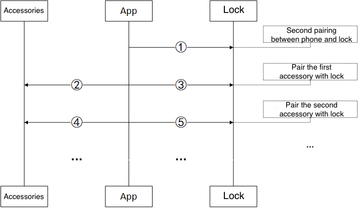
In the preceding figure, Steps 1, 3, and 5 are implemented with the DP dp_id=70 of the smart lock. Steps 2 and 4 are implemented through the pass-through channel of the accessories.
Step 1 indicates the second pairing between the mobile phone and the smart lock. When the mobile phone opens the smart lock panel for the first time, DP 70 is sent to the smart lock. The following fields are included in the command:
- Central ID:
0xFFFF, the ID of the mobile phone. - Peripheral ID: The smart lock ID that is assigned by the Tuya Developer Platform.
- Random number: All bits set to
0for the initial number. - Operation: Add.
- Central ID to be configured: The mobile phone ID that is assigned by the Tuya Developer Platform.
- Central random number to be configured: The mobile phone random number that is assigned by the Tuya Developer Platform.
Step 2 indicates the pairing between the first accessory and the smart lock. When pairing is started, the mobile phone sends data to the accessory through the pass-through channel. The following fields are included in the command:
- Operation: Add.
- Accessory ID: The central ID that is assigned by the Tuya Developer Platform to the accessory.
- Accessory random number: The central random number that is assigned by the Tuya Developer Platform to the accessory.
- Peripheral ID: The smart lock ID that is assigned by the Tuya Developer Platform.
- Peripheral
device_id: The unique UUID of the peripheral device. - Peripheral
login_key: Thelogin_keyof the peripheral device.
This step is implemented in the SDK and module. You only need to call the required API operations or use serial commands to enable the pairing function.
Step 3 indicates the pairing between the first accessory and the smart lock. When pairing is started, the mobile phone sends data to the accessory by using DP 70. The following fields are included in the command:
- Central ID:
0xFFFF, the ID of the mobile phone. - Peripheral ID: The smart lock ID that is assigned by the Tuya Developer Platform.
- Random number: The central random number that is assigned by the Tuya Developer Platform to the mobile phone, already sent to the smart lock in Step 1.
- Operation: Add.
- Central ID to be configured: the accessory ID that is assigned by the Tuya Developer Platform.
- Central random number to be configured: the accessory random number that is assigned by the Tuya Developer Platform.
Step 4 is the same as Step 2.
Step 5 is the same as Step 3.
The smart lock stores the following information:
-
The central ID and central random number of the app
-
The central ID and central random number of one or more accessories
-
The peripheral ID of the smart lock
An accessory stores the following information:
-
The central ID and central random number of the accessory
-
One or more smart lock peripheral IDs
If either of Steps 2 and 3 is successful, the pairing operation between the first accessory and the smart lock is regarded as successful.
-
If Step 2 is successful but Step 3 failed, open the smart lock panel and perform Step 3 to synchronize data. Then, the accessory is paired with the smart lock.
-
If Step 2 failed but Step 3 is successful, open the accessory panel and perform Step 2 to synchronize data. Then, the accessory is paired with the smart lock.
-
These rules apply to Steps 4 and 5.
Appendix
| Byte(s) | Description | Description | Example | |||
|---|---|---|---|---|---|---|
| 1 | Start time | 4-byte unsigned integer in big endian |
Example: 123-456-789 (Unix timestamp) = 0x075BCD15 (hex) If the validity is permanent, the start date and time is 0x386CD300. |
07 | ||
| 2 | 5B | |||||
| 3 | CD | |||||
| 4 | 15 | |||||
| 5 | End time | 4-byte unsigned integer in big endian |
Example: 999-999-999 (Unix timestamp) = 0x3B9AC9FF (hex) If the validity is permanent, the end time is 0x72BC9B7F. |
3B | ||
| 6 | 9A | |||||
| 7 | C9 | |||||
| 8 | FF | |||||
| 9 | The recurring patterns: | 0x00: One-time | 0x01: Daily schedule | 0x02: Weekly schedule | 0x03: Monthly schedule | |
| 10 | Recurring bit 1 | For a one-time schedule, bytes 10 to 17 are 0. |
This field defaults to 0x00. |
This field defaults to 0x00. |
Bit 7: Default to 0 Bit 6: The 31st of a month … Bit 0: The 25th of a month |
|
| 11 | Recurring bit 2 | This field defaults to 0x00. |
This field defaults to 0x00. |
Bit 7: The 24th of a month … Bit 0: The 17th of a month |
||
| 12 | Recurring bit 3 | This field defaults to 0x00. |
This field defaults to 0x00. |
Bit 7: The 16th of a month … Bit 0: The 9th of a month |
||
| 13 | Recurring bit 4 | This field defaults to 0x00. |
Bit 7: Default to 0 Bit 6: Saturday … Bit 1: Monday Bit 0: Sunday |
Bit 7: The 8th of a month … Bit 0: The 1st of a month |
||
| 14 | Start time 1 (hour) in a day | Start time: 08:30 | 08 (decimal) | |||
| 15 | Start time 2 (minute) in a day | 30 (decimal) | ||||
| 16 | End time 1 (hour) in a day | End time: 20:30 | 20 (decimal) | |||
| 17 | End time 2 (minute) in a day | 30 (decimal) | ||||
When the user adds or modifies unlocking methods, the recurring validity period and the access times are both applied. There are two use cases:
- When the access times are
0x00, this indicates permanent access. You only need to process the recurring pattern of the validity. - When the recurring pattern is
0x00, this indicates one-time access. You only need to process the access times.
For example, schedule a password to be valid every Monday to Friday from 08:00 to 08:30 from 2018-01-26 08:00:00 to 2018-08-08 09:56:32.
2018-01-26 08:00:00=1516924800(Unix timestamp) =0x5A6A6F80(hex)2018-08-08 09:56:32=1533693392(Unix timestamp) =0x5B6A4DD0(hex)- The recurring pattern:
0x02indicates a weekly schedule. - Recurring bit 1 = Recurring bit 2 = Recurring bit 3 =
0x00. - Recurring bit 4 =
0x3E(Monday to Friday) - The start time 1 is
0x08, and the start time 2 is0x00. - The end time 1 is
0x08, and the end time 2 is0x1E.
Based on these rules, the validity is set to 0x 5A6A6F80 5B6A4DD0 02 0000003E 0800 081E.
Is this page helpful?
YesFeedbackIs this page helpful?
YesFeedback


