MCU Integration Protocol
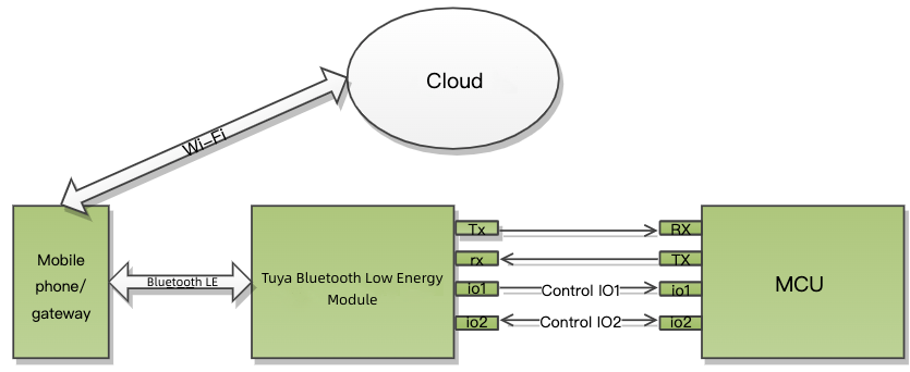
This topic describes the serial protocol that is used to implement serial communication between Tuya’s Bluetooth Low Energy (LE) module and a third-party MCU, as shown in the following diagram.
Serial communication
| Term | Description |
|---|---|
| Baud (bps) | 9600 |
| Data bit | 8 |
| Parity | None |
| Stop bit | 1 |
| Data flow control | None |
Terms
| Term | Description |
|---|---|
| Data point (DP) | A data point (DP) is an abstract representation of a product function. |
| PID | A PID is an abstract representation of a collection of physical devices that have the same configurations and properties. Each product created on the Tuya Developer Platform is assigned a unique PID that is associated with the product information, including DPs, app control panel, and purchase information. |
Packet structure
| No. | Length (byte) | Field | Description |
|---|---|---|---|
| 0 1 |
2 | Header | 0x55 0xAA |
| 2 | 1 | Version number | The protocol version. |
| 3 | 1 | Command (CMD) | The frame type. |
| 4 5 |
2 | Data length (Len) | High-order 8 bits Low-order 8 bits |
| 6 to 6+Len-1 | Len | Data | - |
| 6+Len | 1 | CRC8 | Start from the header, add up all the bytes, and then divide the sum by 256 to get the remainder. |
All data greater than one byte is transmitted in big-endian format.
DP format
| Field | Length (byte) | Description |
|---|---|---|
| dp_id | 1 | The ID of a DP. |
| dp_type | 1 | The data type of a DP. |
| dp_data_len | 2 | The data length of a DP. |
| dp_data_value | dp_data_len | The data of a DP. |
The value range and description of dp_type (cloud defined):
| dp_type | Value | Length (byte) | Description |
|---|---|---|---|
| Raw | 0x00 | 1 to 255 | The raw data in hexadecimal format |
| Boolean | 0x01 | 1 | Boolean type |
| Value | 0x02 | 4 | Integer type |
| String | 0x03 | 0 to 255 | String type. Its value can be empty. |
| Enum | 0x04 | 1 | Enumeration type |
Firmware types
-
To support features specific to a product category, a range of extended protocols are provided to help you implement the required features on top of the generic firmware. This documentation describes both the generic protocol and the protocol specific to low power devices and smart locks.
-
The generic protocol is supported on all generic firmware, while the low power protocol is only supported on specific generic firmware. The smart lock protocol is supported on the generic firmware for specific product categories.
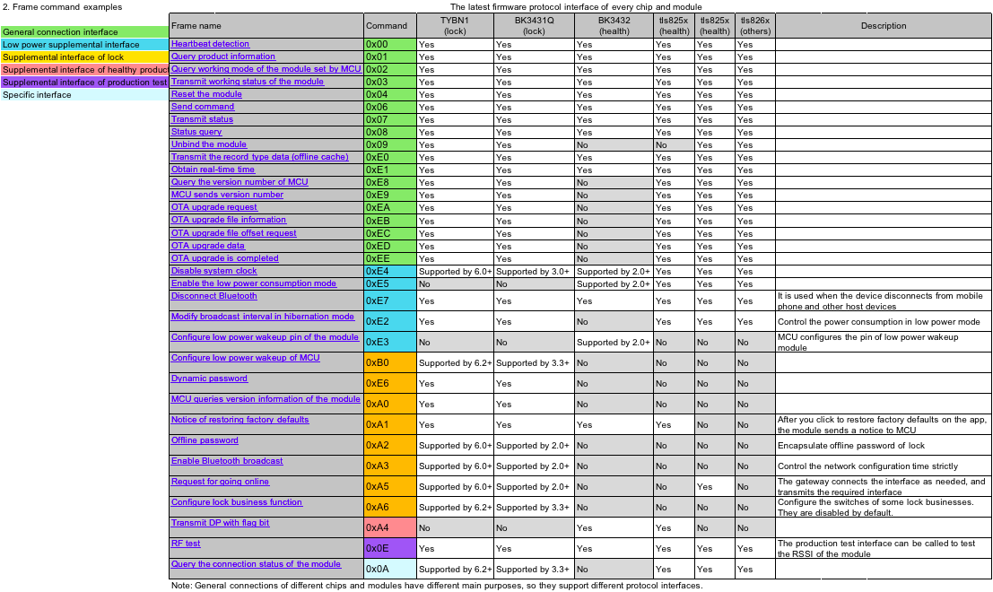
The following table lists the firmware support information.
| Product category | Chip/module |
|---|---|
| Locks | TYBN1 and BK3431Q |
| Health or shared products | BK3432, BK3431Q, and TYBT3L |
| Basis | BK3432, TYBT3L, and TYBT4L |
Certain module models support multiple types of generic firmware.
Supported interfaces
The generic firmware support for specific protocols depends on product categories and models.
The table below shows the interfaces supported by the generic firmware for various product categories.
Generic protocol
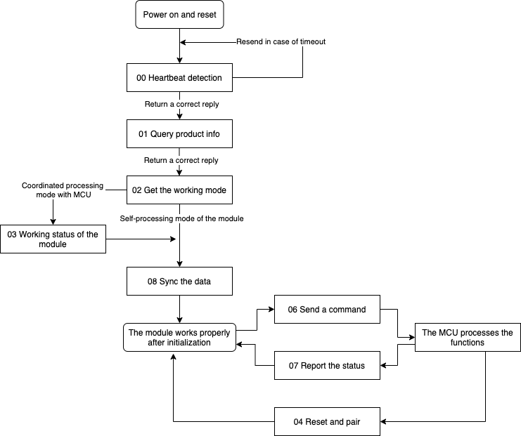
The following diagram shows the basic process of the protocol.
Heartbeat mechanism (0x00)
After power on, the module will send a heartbeat packet to the MCU every 3 seconds. If the MCU correctly responds to a heartbeat, it indicates the MCU works properly. After the first-time heartbeat communication, the module will send the MCU a command to get product information.
The MCU can determine whether the module works properly by the regular heartbeat check. If the MCU does not receive a heartbeat packet as expected, it can use the reset pin to reset the module.
After getting the MCU information, the module checks the heartbeat every 10 seconds in standard power mode. In low power mode, there is no heartbeat check.
The Telink Bluetooth modules do not perform heartbeat checks both in low power mode and after getting the MCU information. They cannot detect whether the MCU has been restarted.
The module sends the following data.
| No. | Length (byte) | Field | Description |
|---|---|---|---|
| 0 1 |
2 | Header | 0x55 0xAA |
| 2 | 1 | Version number | 0x00 |
| 3 | 1 | Command (CMD) | 0x00 |
| 4 5 |
2 | Data length | 0x00 0x00 |
| 6 | 1 | CRC8 | Start from the header, add up all the bytes, and then divide the sum by 256 to get the remainder. |
The MCU returns the following data.
| No. | Length (byte) | Field | Description |
|---|---|---|---|
| 0 1 |
2 | Header | 0x55 0xAA |
| 2 | 1 | Version number | 0x00 |
| 3 | 1 | Command (CMD) | 0x00 |
| 4 5 |
2 | Data length | 0x00 0x01 |
| 6 | 1 | State | See the following table. |
| 7 | 1 | CRC8 | Start from the header, add up all the bytes, and then divide the sum by 256 to get the remainder. |
| Return value | Description |
|---|---|
| 0x00 | The MCU returns this value on the first-time heartbeat communication after power on. The module uses this value to determine whether the MCU restarts during operation. |
| 0x01 | The MCU returns this value except for the first response after a restart. |
Get MCU information (0x01)
- Product key: 8-byte value assigned to each product for storing product information in the cloud.
- Product information refers to the information about the product ID (PID).
The module sends the following data.
| No. | Length (byte) | Field | Description |
|---|---|---|---|
| 0 1 |
2 | Header | 0x55 0xAA |
| 2 | 1 | Version number | 0x00 |
| 3 | 1 | Command (CMD) | 0x01 |
| 4 5 |
2 | Data length | 0x00 0x00 |
| 6 | 1 | CRC8 | Start from the header, add up all the bytes, and then divide the sum by 256 to get the remainder. |
The MCU returns the following data.
| No. | Length (byte) | Field | Description |
|---|---|---|---|
| 0 1 |
2 | Header | 0x55 0xAA |
| 2 | 1 | Version number | 0x00 |
| 3 | 1 | Command (CMD) | 0x01 |
| 4 5 |
2 | Data length | 0x00 0x0d |
| 6 to 18 | 0x0d | Data | See the following table. |
| 19 | 1 | CRC8 | Start from the header, add up all the bytes, and then divide the sum by 256 to get the remainder. |
Data format:
| 1 to 8 | 9 to 13 |
|---|---|
| PID | The reserved field. |
Example: 55 AA 00 01 00 0D 66 74 62 38 78 32 78 30 31 2E 30 2E 30 C0, indicating the PID is ftb8x2x0 and the MCU version number is 1.0.0.
PID is an 8-digit string, such as ftb8x2x0.
The reserved field was meant for the MCU version number, but since the module does not parse this field, it is reserved. The MCU reports its version number using the command 0xE8 or 0xE9.
Request working mode (0x02)
The working mode indicates how the network status is indicated and the way to trigger module reset. Theoretically, the module can work in the following two modes:
- The module works with the MCU to process network events. Through serial communication, the module sends the network status to the MCU for LED indication. The MCU can send the command to reset the module when necessary.
- The module processes network events itself: Not supported.
The Bluetooth module only supports the first collaboration mode.
The module sends the following data.
| No. | Length (byte) | Field | Description |
|---|---|---|---|
| 0 1 |
2 | Header | 0x55 0xAA |
| 2 | 1 | Version number | 0x00 |
| 3 | 1 | Command (CMD) | 0x02 |
| 4 5 |
2 | Data length | 0x00 0x00 |
| 6 | 1 | CRC8 | Start from the header, add up all the bytes, and then divide the sum by 256 to get the remainder. |
Example: 55 aa 00 02 00 00 01
The MCU returns the following data.
| No. | Length (byte) | Field | Description |
|---|---|---|---|
| 0 1 |
2 | Header | 0x55 0xAA |
| 2 | 1 | Version number | 0x00 |
| 3 | 1 | Command (CMD) | 0x02 |
| 4 5 |
2 | Data length | 0x00 0x00 |
| 6 | 1 | CRC8 | Start from the header, add up all the bytes, and then divide the sum by 256 to get the remainder. |
Example: 55 AA 00 02 00 00 01
Send pairing state (0x03)
The module sends this command to the MCU to notify its current state, which can be unbound (0x00), bound but not connected (0x01), or bound and connected (0x02).
The module will send its current state to the MCU after responding to the command 0x02, or when the state changes.
The module sends the following data.
| No. | Length (byte) | Field | Description |
|---|---|---|---|
| 0 1 |
2 | Header | 0x55 0xAA |
| 2 | 1 | Version number | 0x00 |
| 3 | 1 | Command (CMD) | 0x03 |
| 4 5 |
2 | Data length | 0x00 0x01 |
| 6 | 1 | State | See the following table. |
| 7 | 1 | CRC8 | Start from the header, add up all the bytes, and then divide the sum by 256 to get the remainder. |
| State | Description | Note |
|---|---|---|
| 0x00 0x01 |
Unbound Bound but not connected |
For health or shared devices, they can be added to the mobile app either in the unbound state or the bound but not connected state. |
| 0x02 | Bound and connected | For health or shared devices, this state indicates that they have been added to the mobile app and connected to the cloud. |
Reset the module (0x04)
The MCU sends this command to direct the Bluetooth module to be disconnected and unbound. The module’s virtual ID and cache data will be cleared.
For Bluetooth modules using Telink chips, resetting the module with the command 0x04 will not clear the virtual ID.
The MCU sends the following data.
| No. | Length (byte) | Field | Description |
|---|---|---|---|
| 0 1 |
2 | Header | 0x55 0xAA |
| 2 | 1 | Version number | 0x00 |
| 3 | 1 | Command (CMD) | 0x04 |
| 4 5 |
2 | Data length | 0x00 0x00 |
| 6 | 1 | CRC8 | Start from the header, add up all the bytes, and then divide the sum by 256 to get the remainder. |
Example: 55 aa 00 04 00 00 03
The module returns the following data.
| No. | Length (byte) | Field | Description |
|---|---|---|---|
| 0 1 |
2 | Header | 0x55 0xAA |
| 2 | 1 | Version number | 0x00 |
| 3 | 1 | Command (CMD) | 0x04 |
| 4 5 |
2 | Data length | 0x00 0x00 |
| 6 | 1 | CRC8 | Start from the header, add up all the bytes, and then divide the sum by 256 to get the remainder. |
Example: 55 AA 00 04 00 00 03
Send commands (0x06)
- For more information about DPs, see DP format.
- One command can contain data units of multiple DPs.
- The module sends control commands and the MCU reports DP status, which occurs asynchronously.
The module sends the following data.
| No. | Length (byte) | Field | Description |
|---|---|---|---|
| 0 1 |
2 | Header | 0x55 0xAA |
| 2 | 1 | Version number | 0x00 |
| 3 | 1 | Command (CMD) | 0x06 |
| 4 5 |
2 | Data length (Len) | High-order 8 bits Low-order 8 bits |
| 6 to 6+Len-1 | Len | DP | See the following table. |
| 6+Len | 1 | CRC8 | Start from the header, add up all the bytes, and then divide the sum by 256 to get the remainder. |
DP format:
| 1 | 2 | 3 to 4 | 5 and followings | … | n | n+1 | n+1 to n+2 | n+3 and followings |
|---|---|---|---|---|---|---|---|---|
| dp1_id | dp1_type | dp1_len | dp1_data | … | dpN_id | dpN_type | dpN_len | dpN_data |
Example: 55 aa 00 06 00 05 03 01 00 01 01 10
The MCU returns the following data.
None
Report status (0x07)
- For more information about DPs, see DP format.
- The MCU can report data units of multiple DPs.
- The MCU asynchronously reports DP status, which can be triggered by three mechanisms.
- After the MCU executes the command received from the module, it reports the changed DP status to the module.
- When the MCU proactively detects status changes of DPs, it reports the changed DP status to the module.
- When the MCU receives the DP status query, it sends the status of all DPs to the module.
The MCU sends the following data.
| No. | Length (byte) | Field | Description |
|---|---|---|---|
| 0 1 |
2 | Header | 0x55 0xAA |
| 2 | 1 | Version number | 0x00 |
| 3 | 1 | Command (CMD) | 0x07 |
| 4 5 |
2 | Data length (Len) | High-order 8 bits Low-order 8 bits |
| 6 to 6+Len-1 | Len | DP | See the following table. |
| 6+Len | 1 | CRC8 | Start from the header, add up all the bytes, and then divide the sum by 256 to get the remainder. |
DP format:
| 1 | 2 | 3 to 4 | 5 and followings | … | n | n+1 | n+1 to n+2 | n+3 and followings |
|---|---|---|---|---|---|---|---|---|
| dp1_id | dp1_type | dp1_len | dp1_data | … | dpN_id | dpN_type | dpN_len | dpN_data |
Example: 55 aa 00 06 00 05 03 01 00 01 01 10
The module returns the following data.
| No. | Length (byte) | Field | Description |
|---|---|---|---|
| 0 1 |
2 | Header | 0x55 0xAA |
| 2 | 1 | Version number | 0x00 |
| 3 | 1 | Command (CMD) | 0x07 |
| 4 5 |
2 | Data length | 0x00 0x01 |
| 6 | 1 | State | See the following table. |
| 7 | 1 | CRC8 | Start from the header, add up all the bytes, and then divide the sum by 256 to get the remainder. |
| Return value |
|---|
| 0x00: Success |
| 0x01: Failure |
Query status (0x08)
- The module asynchronously queries the status of all object DPs. When the MCU receives queries, it sends the status of DPs to the module through the command
0x07. - The module sends DP status queries when the following two events occur.
- For a bound and connected module, it detects that the MCU is restarted based on the heartbeat communication. Note that Telink generic firmware does not support detecting MCU restart.
- A bound module is reconnected after it goes offline.
The module sends the following data.
| No. | Length (byte) | Field | Description |
|---|---|---|---|
| 0 1 |
2 | Header | 0x55 0xAA |
| 2 | 1 | Version number | 0x00 |
| 3 | 1 | Command (CMD) | 0x08 |
| 4 5 |
2 | Data length | 0x00 0x00 |
| 6 | 1 | CRC8 | Start from the header, add up all the bytes, and then divide the sum by 256 to get the remainder. |
Example: 55 aa 00 08 00 00 07
The MCU returns nothing.
Unbind the module (0x09)
- After the MCU sends this command, the Bluetooth module will be disconnected and unbound from the mobile app. Its virtual ID and cache data will not be cleared.
- This command does not apply to the generic firmware for the health or shared devices.
- For more information, see Supported interfaces.
The MCU sends the following data.
| No. | Length (byte) | Field | Description |
|---|---|---|---|
| 0 1 |
2 | Header | 0x55 0xAA |
| 2 | 1 | Version number | 0x00 |
| 3 | 1 | Command (CMD) | 0x09 |
| 4 5 |
2 | Data length | 0x00 0x00 |
| 6 | 1 | CRC8 | Start from the header, add up all the bytes, and then divide the sum by 256 to get the remainder. |
The module returns the following data.
| No. | Length (byte) | Field | Description |
|---|---|---|---|
| 0 1 |
2 | Header | 0x55 0xAA |
| 2 | 1 | Version number | 0x00 |
| 3 | 1 | Command (CMD) | 0x09 |
| 4 5 |
2 | Data length | 0x00 0x01 |
| 6 | 1 | State | See the following table. |
| 7 | 1 | CRC8 | Start from the header, add up all the bytes, and then divide the sum by 256 to get the remainder. |
| Return value |
|---|
| 0x00: Success |
| 0x01: Failure |
Query the module’s connection status (0x0A)
- The MCU proactively queries the current connection status of the module. The module returns its status through the command
0x03. - The module sends this command to the MCU to notify its current state, which can be unbound (
0x00), bound but not connected (0x01), or bound and connected (0x02).
The MCU sends the following data.
| No. | Length (byte) | Field | Description |
|---|---|---|---|
| 0 1 |
2 | Header | 0x55 0xAA |
| 2 | 1 | Version number | 0x00 |
| 3 | 1 | Command (CMD) | 0x0A |
| 4 5 |
2 | Data length | 0x00 0x00 |
| 6 | 1 | CRC8 | Start from the header, add up all the bytes, and then divide the sum by 256 to get the remainder. |
Report record-type data (0xE0)
- If the module is offline when receiving reported data from the MCU, it will save the data to its flash memory and send the stranded data after going online. After the last piece of stranded data is sent to the cloud, the module will release the cache.
- The module can cache up to N pieces of DP data. When the limit is reached, the newest record will overwrite the oldest one.
- The nRF52832 and BK3431Q based modules can store up to 80 pieces of data, with a maximum length of 200 bytes per piece.
- The BK3432 based modules can store up to 32 pieces of data, with a maximum length of 32 bytes per piece.
- The time drift of the module’s internal clock is less than one minute in 24 hours. The module will sync its clock with the server time each time it is connected to the cloud. If you require highly accurate time, you can report data using the MCU’s timestamp.
To ensure reliable data transmission, we recommend you use this command to report record-type data no matter what connection status the module is in.
The MCU sends the following data.
| No. | Length (byte) | Field | Description |
|---|---|---|---|
| 0 1 |
2 | Header | 0x55 0xAA |
| 2 | 1 | Version number | 0x00 |
| 3 | 1 | Command (CMD) | 0xE0 |
| 4 5 |
2 | Data length (Len) | High-order 8 bits Low-order 8 bits |
| 6 to 6+Len-1 | Len | Data | See the following table. |
| 6+Len | 1 | CRC8 | Start from the header, add up all the bytes, and then divide the sum by 256 to get the remainder. |
Data format:
| 1 | 2 to x | x | x+1 | x+2 to x+3 | x+4 and followings | … | n | n+1 | n+1 to n+2 | n+3 and followings |
|---|---|---|---|---|---|---|---|---|---|---|
| TYPE | Time_Str | dp1_id | dp1_type | dp1_len | dp1_data | … | dpN_id | dpN_type | dpN_len | dpN_data |
Time_Str: 13-digit Unix timestamp.
| TYPE | Description |
|---|---|
| 0x01 | Format 1: Report status with the time data from the Bluetooth module. |
| 0x03 | Format 3: Report status with the time data from the MCU. |
unix_time_string: It is required only when TYPE is set to 0x03.
Example:
-
Format 1: Report status with the time data from the Bluetooth module.
55 AA 00 E0 00 17 01 66 02 00 04 00 00 00 01 67 03 00 05 72 77 72 77 77 68 04 00 01 00 89 -
Format 3: Report status with the time data from the MCU.
55 AA 00 E0 00 28 03 31 35 38 39 31 36 38 33 32 37 30 30 30 66 02 00 04 00 00 00 01 67 03 00 09 72 77 72 77 77 61 66 61 66 68 04 00 01 00 D0
The module returns the following data.
| No. | Length (byte) | Field | Description |
|---|---|---|---|
| 0 1 |
2 | Header | 0x55 0xAA |
| 2 | 1 | Version number | 0x00 |
| 3 | 1 | Command (CMD) | 0xE0 |
| 4 5 |
2 | Data length | 0x00 0x01 |
| 6 | 1 | State | See the following table. |
| 7 | 1 | CRC8 | Start from the header, add up all the bytes, and then divide the sum by 256 to get the remainder. |
| Return value |
|---|
| 0x00: Success |
| Other values: Failure |
Get the current time (0xE1)
- We recommend you use the date and time format
0x02. - After the module is online, it will proactively sync the server time with the MCU.
The MCU returns the following data.
| No. | Length (byte) | Field | Description |
|---|---|---|---|
| 0 1 |
2 | Header | 0x55 0xAA |
| 2 | 1 | Version number | 0x00 |
| 3 | 1 | Command (CMD) | 0xE1 |
| 4 5 |
2 | Data length | 0x00 0x01 |
| 6 | 1 | Time_Type | See the following table. |
| 7 | 1 | CRC8 | Start from the header, add up all the bytes, and then divide the sum by 256 to get the remainder. |
Time_Type:
| Time_Type | Description |
|---|---|
| 0x00 | Format 0: 7-byte date and time value and 2-byte time zone value. |
| 0x01 | Format 1: 13-byte Unix time value in milliseconds and 2-byte time zone value. |
| 0x02 | Format 2: 7-byte date and time value and 2-byte time zone value. |
- Request for custom time data in format 0 might cause compatibility issues across different chipset platforms. This format will be deprecated in the future. We recommend you use the date and time format
0x02. - The Telink based module does not support format 0. The module will return time data in format 2 if it receives a request for time data in format 0.
- The value of the time zone is 100 times the actual time zone. For example,
800represents GMT+8.
The module returns the following data.
| No. | Length (byte) | Field | Description |
|---|---|---|---|
| 0 1 |
2 | Header | 0x55 0xAA |
| 2 | 1 | Version number | 0x00 |
| 3 | 1 | Command (CMD) | 0xE1 |
| 4 5 |
2 | Data length (Len) | High-order 8 bits Low-order 8 bits |
| 6 to 6+Len-1 | Len | Time_Data | See the following table. |
| 6+Len | 1 | CRC8 | Start from the header, add up all the bytes, and then divide the sum by 256 to get the remainder. |
Time_Data format 0:
| Result code | Time format | Year | Month | Day | Hour | Minute | Second | Day of week | Time zone |
|---|---|---|---|---|---|---|---|---|---|
| 1 | 2 | 3 | 4 | 5 | 6 | 7 | 8 | 9 | 10 to 11 |
| Result | Time_Type | 2018+year | mon | day | hour | min | sec | week | time_zone |
Time_Data format 1:
| Result code | Time format | Unix timestamp in milliseconds | Time zone |
|---|---|---|---|
| 1 | 2 | 3 to 15 | 16 to 17 |
| Result | Time_Type | unix_time_string | time_zone |
Time_Data format 2:
| Result code | Time format | Year | Month | Day | Hour | Minute | Second | Day of week | Time zone |
|---|---|---|---|---|---|---|---|---|---|
| 1 | 2 | 3 | 4 | 5 | 6 | 7 | 8 | 9 | 10 to 11 |
| Result | Time_Type | 2000+year | mon | day | hour | min | sec | week | time_zone |
If result is 0x00, it indicates success. All other values indicate failure.
Example:
Time_Dataformat 0:- The MCU sends
55 AA 00 E1 00 01 00 E1. - The module returns
55 AA 00 E1 00 0B 00 00 01 0C 1E 0F 34 1F 01 03 20 9C, indicating 15:52:31, Monday, December 30, 2019, GMT+8.
- The MCU sends
Time_Dataformat 1:- The MCU sends
55 AA 00 E1 00 01 01 E2. - The module returns
55 AA 00 E1 00 11 00 01 31 35 37 37 36 39 32 33 39 35 30 30 30 03 20 BB, indicating a timestamp1577692395000, GMT+8.
- The MCU sends
Time_Dataformat 2:- The MCU sends
55 AA 00 E1 00 01 02 E3. - The module returns
55 AA 00 E1 00 0B 00 02 13 0C 1E 10 09 29 01 03 20 90, indicating 16:09:35, Monday, December 30, 2019, GMT+8.
- The MCU sends
MCU OTA updates
Query MCU’s version number (0xE8)
- The module uses this command to get the MCU version number while it queries the MCU information.
- For more information, see Supported interfaces.
The module sends the following data.
| No. | Length (byte) | Field | Description |
|---|---|---|---|
| 0 1 |
2 | Header | 0x55 0xAA |
| 2 | 1 | Version number | 0x00 |
| 3 | 1 | Command (CMD) | 0xE8 |
| 4 5 |
2 | Data length | 0x00 0x00 |
| 6 | 1 | CRC8 | Start from the header, add up all the bytes, and then divide the sum by 256 to get the remainder. |
The MCU returns the following data.
| No. | Length (byte) | Field | Description |
|---|---|---|---|
| 0 1 |
2 | Header | 0x55 0xAA |
| 2 | 1 | Version number | 0x00 |
| 3 | 1 | Command (CMD) | 0xE8 |
| 4 5 |
2 | Data length | 0x00 0x06 |
| 6 to 11 | 6 | DATA | See the following table. |
| 12 | 1 | CRC8 | Start from the header, add up all the bytes, and then divide the sum by 256 to get the remainder. |
Data format:
| 1 to 3 | 4 to 6 |
|---|---|
| Soft_Ver | Hard_ver |
Soft_Ver: The firmware version of the MCU. For example, 0x01 00 02 represents v1.0.2.
Hard_ver: The hardware version of the MCU, the PCBA version number.
Proactive MCU version reporting (0xE9)
- The MCU proactively sends its version number to the module after startup (generally after the UART initialization). If the module does not respond, the MCU will resend the message.
- For more information, see Supported interfaces.
The MCU returns the following data.
| No. | Length (byte) | Field | Description |
|---|---|---|---|
| 0 1 |
2 | Header | 0x55 0xAA |
| 2 | 1 | Version number | 0x00 |
| 3 | 1 | Command (CMD) | 0xE9 |
| 4 5 |
2 | Data length | 0x00 0x06 |
| 6 to 11 | 6 | DATA | See the following table. |
| 12 | 1 | CRC8 | Start from the header, add up all the bytes, and then divide the sum by 256 to get the remainder. |
Data format:
| 1 to 3 | 4 to 6 |
|---|---|
| Soft_Ver | Hard_ver |
Soft_Ver: The firmware version of the MCU. For example, 0x01 00 02 represents v1.0.2.
Hard_ver: The hardware version of the MCU, the PCBA version number.
The module returns the following data.
| No. | Length (byte) | Field | Description |
|---|---|---|---|
| 0 1 |
2 | Header | 0x55 0xAA |
| 2 | 1 | Version number | 0x00 |
| 3 | 1 | Command (CMD) | 0xE9 |
| 4 5 |
2 | Data length | 0x00 0x01 |
| 6 | 1 | State | See the following table. |
| 7 | 1 | CRC8 | Start from the header, add up all the bytes, and then divide the sum by 256 to get the remainder. |
| Return value |
|---|
| 0x00: Success |
| Other values: Failure |
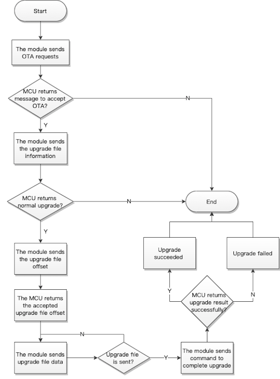
MCU OTA update process
Initiate an update request (0xEA)
- The module initiates an update request to get the maximum length of one packet for serial transmission.
- For more information, see Supported interfaces.
The module sends the following data.
| No. | Length (byte) | Field | Description |
|---|---|---|---|
| 0 1 |
2 | Header | 0x55 0xAA |
| 2 | 1 | Version number | 0x00 |
| 3 | 1 | Command (CMD) | 0xEA |
| 4 5 |
2 | Data length | 0x00 0x02 |
| 6 to 7 | 2 | The maximum length of one packet len1 |
See the description below. |
| 8 | 1 | CRC8 | Start from the header, add up all the bytes, and then divide the sum by 256 to get the remainder. |
Len1: The maximum length of a packet that can be transmitted over the serial port, in the unit of bytes.
Example: 55 AA 00 EA 00 02 00 C8 B3
The MCU returns the following data.
| No. | Length (byte) | Field | Description |
|---|---|---|---|
| 0 1 |
2 | Header | 0x55 0xAA |
| 2 | 1 | Version number | 0x00 |
| 3 | 1 | Command (CMD) | 0xEA |
| 4 5 |
2 | Data length | 0x00 0x06 |
| 6 to 11 | 6 | Data | See the following table. |
| 12 | 1 | CRC8 | Start from the header, add up all the bytes, and then divide the sum by 256 to get the remainder. |
Data format:
| 1 | 2 to 4 | 5 to 6 |
|---|---|---|
| Flag | The MCU’s current firmware version (Version) | The MCU-specified maximum length of a packet (len2) |
-
Flag:
0x00indicates the update is accepted.0x01indicates the update is rejected. -
Version: The current firmware version. For example,
0x01 00 02representsv1.0.2. -
Len1: The module-specified maximum length of a packet.
-
Len2: The MCU-specified maximum length of a packet. If
len1is less thanlen2,len1prevails. Otherwise,len2prevails.
Example: 55 AA 00 EA 00 06 00 01 00 00 00 C8 B8
Send the update information (0xEB)
- The module sends the information about the firmware update to the MCU. The MCU determines whether to accept the update accordingly.
- For more information, see Supported interfaces.
The module sends the following data.
| No. | Length (byte) | Field | Description |
|---|---|---|---|
| 0 1 |
2 | Header | 0x55 0xAA |
| 2 | 1 | Version number | 0x00 |
| 3 | 1 | Command (CMD) | 0xEB |
| 4 5 |
2 | Data length | 0x00 0x23 |
| 6 to 40 | 35 | Data | See the following table. |
| 41 | 1 | CRC8 | Start from the header, add up all the bytes, and then divide the sum by 256 to get the remainder. |
Data format:
| 8 bytes | 3 bytes | 16 bytes | 4 bytes | 4 bytes |
|---|---|---|---|---|
| The PID. | The firmware version. | The MD5 hash. | The file length. | The CRC32 checksum. |
- PID: The PID of the MCU.
- Firmware version: The version of firmware to be installed. For example,
0x010002representsv1.0.2. - MD5 hash: The MD5 value of the firmware update.
- File length: The total length of the firmware update, in bytes.
- CRC32 checksum: The CRC32 value of the firmware update.
The MCU returns the following data.
| No. | Length (byte) | Field | Description |
|---|---|---|---|
| 0 1 |
2 | Header | 0x55 0xAA |
| 2 | 1 | Version number | 0x00 |
| 3 | 1 | Command (CMD) | 0xEB |
| 4 5 |
2 | Data length | 0x00 0x19 |
| 6 to 30 | 25 | Data | See the following table. |
| 31 | 1 | CRC8 | Start from the header, add up all the bytes, and then divide the sum by 256 to get the remainder. |
Data format:
| 1 byte | 4 bytes | 4 bytes | 16 bytes |
|---|---|---|---|
| STATE | The size of the update that has already been downloaded. | The CRC32 checksum of the update that has already been downloaded. | The MD5 hash value of the update that has already been downloaded. (Not used currently) |
STATE:
- 0x00: The update is performed as expected.
- 0x01: The received PID does not match the one written to the device.
- 0x02: The update version is earlier than or equal to the current version.
- 0x03: The update size exceeds the upper limit.
Other fields: Reserved
The device returns information about the update that has been downloaded to continue downloading from where it was interrupted. After receiving the response message, the app will calculate the CRC32 checksum and compare it to the value received. If the two match exactly, the app will change the start offset to the received data length in the following transmission request. Otherwise, the start offset is 0, meaning downloading from scratch.
The resumable transfer also follows the normal update process, starting from initiating an update request. If the module operates in any state rather than bound and connected, the MCU should reset the update status if any to start the following update procedure.
Request the update offset (0xEC)
For more information, see Supported interfaces.
The module sends the following data.
| No. | Length (byte) | Field | Description |
|---|---|---|---|
| 0 1 |
2 | Header | 0x55 0xAA |
| 2 | 1 | Version number | 0x00 |
| 3 | 1 | Command (CMD) | 0xEC |
| 4 5 |
2 | Data length | 0x00 0x04 |
| 6 to 9 | 4 | offset | See the following table. |
| 10 | 1 | CRC8 | Start from the header, add up all the bytes, and then divide the sum by 256 to get the remainder. |
offset: indicate where to start downloading the update.
Example: 55 AA 00 EA 00 02 00 C8 B3
The MCU returns the following data.
| No. | Length (byte) | Field | Description |
|---|---|---|---|
| 0 1 |
2 | Header | 0x55 0xAA |
| 2 | 1 | Version number | 0x00 |
| 3 | 1 | Command (CMD) | 0xEC |
| 4 5 |
2 | Data length | 0x00 0x04 |
| 6 to 9 | 4 | offset | See the following table. |
| 10 | 1 | CRC8 | Start from the header, add up all the bytes, and then divide the sum by 256 to get the remainder. |
offset: the start offset specified by the MCU.
The start offset address specified by the MCU should take precedence over the one provided by the app. The MCU-specified offset is usually less than the one provided by the app.
Transmit the update (0xED)
For more information, see Supported interfaces.
The module sends the following data.
| No. | Length (byte) | Field | Description |
|---|---|---|---|
| 0 1 |
2 | Header | 0x55 0xAA |
| 2 | 1 | Version number | 0x00 |
| 3 | 1 | Command (CMD) | 0xED |
| 4 5 |
2 | Data length (Len) | High-order 8 bits Low-order 8 bits |
| 6 to 6+Len-1 | Len | Data | See the following table. |
| 6+Len | 1 | CRC8 | Start from the header, add up all the bytes, and then divide the sum by 256 to get the remainder. |
Data format:
| 2 bytes | 2 bytes | 2 bytes | n byte(s) |
|---|---|---|---|
| Packet ID | The size of the current packet n |
The CRC16 checksum of the current packet | The payload of the current packet |
The packet ID starts from 0. The size of the current packet cannot exceed the specified maximum length of a packet.
The MCU returns the following data.
| No. | Length (byte) | Field | Description |
|---|---|---|---|
| 0 1 |
2 | Header | 0x55 0xAA |
| 2 | 1 | Version number | 0x00 |
| 3 | 1 | Command (CMD) | 0xED |
| 4 5 |
2 | Data length | 0x00 0x01 |
| 6 | 1 | State | See the following table. |
| 7 | 1 | CRC8 | Start from the header, add up all the bytes, and then divide the sum by 256 to get the remainder. |
| State | Description |
|---|---|
| 0x00 | Success |
| 0x01 | Packet ID error |
| 0x02 | The data length does not match the expected one. |
| 0x03 | CRC check failed. |
| 0x04 | Others |
Request the update result (0xEE)
For more information, see Supported interfaces.
The module sends the following data.
| No. | Length (byte) | Field | Description |
|---|---|---|---|
| 0 1 |
2 | Header | 0x55 0xAA |
| 2 | 1 | Version number | 0x00 |
| 3 | 1 | Command (CMD) | 0xEE |
| 4 5 |
2 | Data length | 0x00 0x00 |
| 6 | 1 | CRC8 | Start from the header, add up all the bytes, and then divide the sum by 256 to get the remainder. |
The MCU returns the following data.
| No. | Length (byte) | Field | Description |
|---|---|---|---|
| 0 1 |
2 | Header | 0x55 0xAA |
| 2 | 1 | Version number | 0x00 |
| 3 | 1 | Command (CMD) | 0xEE |
| 4 5 |
2 | Data length | 0x00 0x01 |
| 6 | 1 | State | See the following table. |
| 7 | 1 | CRC8 | Start from the header, add up all the bytes, and then divide the sum by 256 to get the remainder. |
Description:
| State | Description |
|---|---|
| 0x00 | Success |
| 0x01 | The total data length error. |
| 0x02 | The data length does not match the expected one. |
| 0x03 | Others |
Production testing
Radio frequency (RF) (0x0E)
-
Perform the received signal strength indicator (RSSI) test on modules to measure the RF performance.
- Test tool: a Tuya’s Bluetooth beacon that broadcasts an identifier named
ty_mdev. - Test steps: Put the beacon around 0.5 meters away from the module. The MCU sends the testing command to the module to initiate a test. The module will scan for the designated identifier and return the RSSI. If the RSSI is greater than -70 dB, the RF performance is acceptable.
- Test tool: a Tuya’s Bluetooth beacon that broadcasts an identifier named
-
The BK3431Q and BK3432 do not support scanning for a designated beacon. You need to perform an RF test with a dongle.
- Test tool: a Tuya’s Bluetooth dongle used to connect to the device under test and return the RSSI.
- Test steps: Put the dongle around 0.5 meters away from the module. The MCU sends the testing command to the module to initiate a test. The dongle will connect to the module and return the RSSI. If the RSSI is greater than -70 dB, the RF performance is acceptable.
- The module must be unbound and operate in the standard power mode.
The MCU sends the following data.
| No. | Length (byte) | Field | Description |
|---|---|---|---|
| 0 1 |
2 | Header | 0x55 0xAA |
| 2 | 1 | Version number | 0x00 |
| 3 | 1 | Command (CMD) | 0x0E |
| 4 5 |
2 | Data length | 0x00 0x00 |
| 6 | 1 | CRC8 | Start from the header, add up all the bytes, and then divide the sum by 256 to get the remainder. |
The module returns the following data.
| No. | Length (byte) | Field | Description |
|---|---|---|---|
| 0 1 |
2 | Header | 0x55 0xAA |
| 2 | 1 | Version number | 0x00 |
| 3 | 1 | Command (CMD) | 0x0E |
| 4 5 |
2 | Data length (Len) | High-order 8 bits Low-order 8 bits |
| 6 to 6+Len-1 | Len | Data | See the following table. |
| 6+Len | 1 | CRC8 | Start from the header, add up all the bytes, and then divide the sum by 256 to get the remainder. |
Data format:
| Data | Description |
|---|---|
| {"ret":true,"rssi":"-55"} | The RSSI is -55 dB. |
| {"ret":false} | The designated signal is not found. |
Low power protocol
The design for low power consumption differs based on the product category. This section describes the details of low power modes.
Low power for TYBN1 and BK3431Q
- After getting the MCU information, the module sends heartbeats to the MCU regularly in standard power mode, but not in low power mode.
- The module can operate in low power or standard power mode.
- Standard power mode: The advertising interval is about 100 ms. Two-way serial communication works.
- Low power mode: The advertising interval is set by the MCU, defaulting to 1 second. If the interval is
0, advertising is turned off. For serial communication, the module only sends data to but does not receive data from the MCU.
- The MCU can pull down or up the serial clock (SCL) pin on the module to make the module enter or exit the sleep mode. The configuration is shown below.
| Chip platform | SCl pin | SCL level in low power | SCL level in standard power |
|---|---|---|---|
| Nordic | IO11 | High | Low |
| Beken | P03 | Low | High |
After the module wakes up, a 20 ms time delay before serial communication is recommended.
In low power mode, the module changes the level of the serial data (SDL) pin for 200 milliseconds to wake up the external MCU for data transmission. After that, the pin will go back to the default level.
| Chip platform | SDL pin | SDL level in transmitting state | SDL level in idle state |
|---|---|---|---|
| Nordic | IO14 | Low | High |
| Beken | P10 | High | Low |
- You do not need to enable the low power mode because it is controlled by the SCL level of the module.
- The system timer cannot be disabled.
The SCL pin configuration for low power control varies depending on chipset platforms. Do not leave the SCL pin on the MCU floating.
Set advertising interval in low power (0xE2)
- This command does not apply to the BK3432 generic firmware for shared devices.
- To further reduce the power consumption in sleep mode, you can use this command to modify the advertising interval. The configuration is stored in the nonvolatile memory. If the interval is set to 0, advertising is turned off. The configuration is stored in the nonvolatile memory.
- The advertisement interval defaults to one second in the low power mode. A long interval means taking more time to connect to a mobile phone. If the phone has poor radio performance, the Bluetooth connection attempt might fail.
- For more information, see Supported interfaces.
The MCU sends the following data.
| No. | Length (byte) | Field | Description |
|---|---|---|---|
| 0 1 |
2 | Header | 0x55 0xAA |
| 2 | 1 | Version number | 0x00 |
| 3 | 1 | Command (CMD) | 0xE2 |
| 4 5 |
2 | Data length | 0x00 0x01 |
| 6 | 1 | Adv_interval | See the following table. |
| 7 | 1 | CRC8 | Start from the header, add up all the bytes, and then divide the sum by 256 to get the remainder. |
Adv_interval: The valid values range from 0 to 20 in units of 100 ms. 0 means turning off advertising.
Example:
55 aa 00 E2 00 01 00 E2, indicating advertising is turned off in low power mode.
55 aa 00 E2 00 01 06 E8, indicating the advertising interval is 600 ms in low power mode.
The module returns the following data.
| No. | Length (byte) | Field | Description |
|---|---|---|---|
| 0 1 |
2 | Header | 0x55 0xAA |
| 2 | 1 | Version number | 0x00 |
| 3 | 1 | Command (CMD) | 0xE2 |
| 4 5 |
2 | Data length | 0x00 0x01 |
| 6 | 1 | State | See the following table. |
| 7 | 1 | CRC8 | Start from the header, add up all the bytes, and then divide the sum by 256 to get the remainder. |
| Return value |
|---|
| 0x00: Success |
| Other values: Failure |
Configure system timer (0xE4)
- If the MCU does not rely on the system time of the module, you can turn off the internal timer of the Telink-based module to reduce the power usage in sleep mode. After both the timer and advertising are turned off, the MCU pulls down the SDA pin to make the module enter deep-sleep mode with current consumption reduced to 3 μA. The configuration is stored in the nonvolatile memory.
- For BK3431Q and TYBN1 modules, writing time data to flash memory is high power consumption and is turned off in sleep mode by default. The timekeeping function is still available because it uses less power. After you turn on the system timer, the time will be saved to the flash memory every one minute, which can fix the issue of RTC reset after the module is restarted. The system timer is turned off by default.
The MCU sends the following data.
| No. | Length (byte) | Field | Description |
|---|---|---|---|
| 0 1 |
2 | Header | 0x55 0xAA |
| 2 | 1 | Version number | 0x00 |
| 3 | 1 | Command (CMD) | 0xE4 |
| 4 5 |
2 | Data length | 0x00 0x01 |
| 6 | 1 | Data | See the following table. |
| 7 | 1 | CRC8 | Start from the header, add up all the bytes, and then divide the sum by 256 to get the remainder. |
Data format:
| Data | Description |
|---|---|
| 0x00 | Turn off system timer |
| 0x01 | Turn off system timer |
The module returns the following data.
| No. | Length (byte) | Field | Description |
|---|---|---|---|
| 0 1 |
2 | Header | 0x55 0xAA |
| 2 | 1 | Version number | 0x00 |
| 3 | 1 | Command (CMD) | 0xE4 |
| 4 5 |
2 | Data length | 0x00 0x01 |
| 6 | 1 | State | See the following table. |
| 7 | 1 | CRC8 | Start from the header, add up all the bytes, and then divide the sum by 256 to get the remainder. |
| Return value |
|---|
| 0x00: Success |
| Other values: Failure |
Disconnect Bluetooth proactively (0xE7)
In an idle state, the MCU can send this command to disconnect the module from the Bluetooth connection to maximize power consumption reduction in the low power mode.
The MCU sends the following data.
| No. | Length (byte) | Field | Description |
|---|---|---|---|
| 0 1 |
2 | Header | 0x55 0xAA |
| 2 | 1 | Version number | 0x00 |
| 3 | 1 | Command (CMD) | 0xE7 |
| 4 5 |
2 | Data length | 0x00 0x00 |
| 6 | 1 | CRC8 | Start from the header, add up all the bytes, and then divide the sum by 256 to get the remainder. |
The module returns the following data.
| No. | Length (byte) | Field | Description |
|---|---|---|---|
| 0 1 |
2 | Header | 0x55 0xAA |
| 2 | 1 | Version number | 0x00 |
| 3 | 1 | Command (CMD) | 0xE7 |
| 4 5 |
2 | Data length | 0x00 0x01 |
| 6 | 1 | State | See the following table. |
| 7 | 1 | CRC8 | Start from the header, add up all the bytes, and then divide the sum by 256 to get the remainder. |
| Return value |
|---|
| 0x00: Success |
| Other values: Failure |
Configure MCU wake-up time (0xB0)
- This command applies to TYBN1 smart lock generic firmware v6.2 or later and BK3431Q smart lock generic firmware v3.3 or later.
- To adjust the wake-up time of the MCU from sleep mode, use this command if the default time of 200 ms does not meet your needs. The module pulls up or down the wake-up pin for a specified time (t) before sending data to the MCU.
- After modification, you must verify whether the specified time works. If not, you need to set a larger value. It is recommended to use the default value unless necessary.
- You can invoke this command after the MCU receives the command 0x02. The configuration is stored in the volatile memory, so it will be reset to the default time of 200 ms when the module is turned off or restarted.
- For more information, see Supported interfaces.
The MCU sends the following data.
| No. | Length (byte) | Field | Description |
|---|---|---|---|
| 0 1 |
2 | Header | 0x55 0xAA |
| 2 | 1 | Version number | 0x00 |
| 3 | 1 | Command (CMD) | 0xB0 |
| 4 5 |
2 | Data length | 0x00 0x01 |
| 6 | 1 | interval | See the description below. |
| 7 | 1 | CRC8 | Start from the header, add up all the bytes, and then divide the sum by 256 to get the remainder. |
interval indicates the wake-up time, ranging from 1 to 20 in the unit of 10 ms.
Example:
55 aa 00 E2 00 01 00 E2, indicating advertising is turned off in low power mode.
55 aa 00 E2 00 01 06 E8, indicating the advertising interval is 600 ms in low power mode.
The module returns the following data.
| No. | Length (byte) | Field | Description |
|---|---|---|---|
| 0 1 |
2 | Header | 0x55 0xAA |
| 2 | 1 | Version number | 0x00 |
| 3 | 1 | Command (CMD) | 0xB0 |
| 4 5 |
2 | Data length | 0x00 0x01 |
| 6 | 1 | State | See the following table. |
| 7 | 1 | CRC8 | Start from the header, add up all the bytes, and then divide the sum by 256 to get the remainder. |
| Return value |
|---|
| 0x00: Success |
| Other values: Failure |
Lock-specific generic protocol
This section describes the extended protocol specific to smart look generic firmware, which does not apply to generic firmware for other categories. For smart locks, BK3431Q generic firmware and TYBN1 generic firmware are currently available.
Verify dynamic password (0xE6)
- The dynamic password is time-dependent. The module time must be in sync with the server time. Otherwise, dynamic password verification will fail. When the module is connected to the app, it will perform time sync.
- The request parameter of the admin password is not supported. Set its length to 0.
- For more information, see Supported interfaces.
The MCU sends the following data.
| No. | Length (byte) | Field | Description |
|---|---|---|---|
| 0 1 |
2 | Header | 0x55 0xAA |
| 2 | 1 | Version number | 0x00 |
| 3 | 1 | Command (CMD) | 0xE6 |
| 4 5 |
2 | Data length (Len) | High-order 8 bits Low-order 8 bits |
| 6 to 6+Len-1 | Len | Data | See the following table. |
| 6+Len | 1 | CRC8 | Start from the header, add up all the bytes, and then divide the sum by 256 to get the remainder. |
Data format:
| 8 bytes | 1 byte | N byte(s) | N byte(s) | … |
|---|---|---|---|---|
| password | The length of the admin password | The first admin password | The second admin password | … |
password: The input password Data[0] to Data[7] ranges from 0 to 9, transferred in ASCII.
The request parameter of the admin password is not supported. Set its length to 0.
Example: The MCU sends a packet that does not contain the admin password.
55 aa 00 E6 00 09 30 31 32 33 34 35 36 37 00 8a
The module returns the following data.
| No. | Length (byte) | Field | Description |
|---|---|---|---|
| 0 1 |
2 | Header | 0x55 0xAA |
| 2 | 1 | Version number | 0x00 |
| 3 | 1 | Command (CMD) | 0xE6 |
| 4 5 |
2 | Data length | 0x00 0x01 |
| 6 | 1 | State | See the following table. |
| 7 | 1 | CRC8 | Start from the header, add up all the bytes, and then divide the sum by 256 to get the remainder. |
| Return value |
|---|
| 0x00: Password verification succeeded. |
| 0x01: Password verification failed. |
Example:
55 AA 00 E6 00 01 01 E7, indicating password verification failed.
55 AA 00 E6 00 01 00 E6, indicating password verified.
Verify dynamic password (New) (0xA7)
- The data of GMT is used to compute the current dynamic password. Therefore, GMT must be provided to the module.
- This command works for the same purpose as the
0xE6but has different parameters. - For more information, see Supported interfaces.
The MCU sends the following data.
| No. | Length (byte) | Field | Description |
|---|---|---|---|
| 0 1 |
2 | Header | 0x55 0xAA |
| 2 | 1 | Version number | 0x00 |
| 3 | 1 | Command (CMD) | 0xA7 |
| 4 5 |
2 | Data length (Len) | High-order 8 bits Low-order 8 bits |
| 6 to 6+Len-1 | Len | Data | See the following table. |
| 6+Len | 1 | CRC8 | Start from the header, add up all the bytes, and then divide the sum by 256 to get the remainder. |
Data format:
| 1 byte | 1 byte | 1 byte | 1 byte | 1 byte | 1 byte | 1 byte | 1 byte | N byte(s) |
|---|---|---|---|---|---|---|---|---|
| TimeSource | 2000+Year | Mon | Day | Hour | Min | Sec | Code_len | Code |
TimeSource:
0x00: Use the time data Year, Mon, Day, Hour, Min, and Sec uploaded by the MCU.0x01: Use the internal time of the module. The Year, Mon, Day, Hour, Min, and Sec uploaded by the MCU are not parsed.
You can set this parameter to 0x00.
The MCU uploads the date and time in GMT. For example, 12:00:00 on June 20, 2020 is represented by 0x14 0x06 0x14 0x04 0x00 0x00 in GMT.
Code_len: The length of the password.
Code: The password. Different from the command 0xE6 that instructs the password to be transferred in ASCII, the command 0xA7 allows the MCU to send the digit directly. For example, 1 is 0x01, and 9 is 0x09.
55 AA 00 A7 00 10 00 14 0A 09 0D 33 2C 08 01 08 05 08 06 04 04 05 7A
The module returns the following data.
| No. | Length (byte) | Field | Description |
|---|---|---|---|
| 0 1 |
2 | Header | 0x55 0xAA |
| 2 | 1 | Version number | 0x00 |
| 3 | 1 | Command (CMD) | 0xA7 |
| 4 5 |
2 | Data length (Len) | High-order 8 bits Low-order 8 bits |
| 6 to 6+Len-1 | Len | State | See the following table. |
| 6+Len | 1 | CRC8 | Start from the header, add up all the bytes, and then divide the sum by 256 to get the remainder. |
| Return value |
|---|
| 0x00: Password verification succeeded. |
| 0x01: Password verification failed. |
Example:
55 AA 00 A7 00 01 01 A8, indicating password verification failed.
55 AA 00 A7 00 01 00 A7, indicating password verified.
Request getting online (0xA5)
- This command allows the module to connect to the gateway on demand. After receiving this command, the module will start a 30s high-frequency advertising. When discovering the flagged advertisement, the Bluetooth central device will connect to the module. After the module is online, the MCU can report the status to the module.
- Typically, the MCU reports the record-type data through
0xE0. If the module is bound but not connected, the MCU will use this command (0xA5) to request to get the module online. Then, after getting online, the module will send the stranded data reported through0xE0. - To report the real-time data, try the following two methods:
- The MCU invokes this command (
0xA5) and waits for an online notification. The module will notify the MCU of its status after getting online. - The MCU can report real-time data in
0x02format through the command0xE0. After getting online, the module will send the stranded data to the app. This method is not recommended.
- The MCU invokes this command (
For more information, see Supported interfaces.
The MCU sends the following data.
| No. | Length (byte) | Field | Description |
|---|---|---|---|
| 0 1 |
2 | Header | 0x55 0xAA |
| 2 | 1 | Version number | 0x00 |
| 3 | 1 | Command (CMD) | 0xA5 |
| 4 5 |
2 | Data length | 0x00 0x00 |
| 6 | 1 | CRC8 | Start from the header, add up all the bytes, and then divide the sum by 256 to get the remainder. |
The module returns the following data.
| No. | Length (byte) | Field | Description |
|---|---|---|---|
| 0 1 |
2 | Header | 0x55 0xAA |
| 2 | 1 | Version number | 0x00 |
| 3 | 1 | Command (CMD) | 0xA5 |
| 4 5 |
2 | Data length | 0x00 0x01 |
| 6 | 1 | State | See the following table. |
| 7 | 1 | CRC8 | Start from the header, add up all the bytes, and then divide the sum by 256 to get the remainder. |
| Return value |
|---|
| 0x00: Success |
| 0x01: Failure |
Offline password (0xA2)
- Offline dynamic passwords can be used to unlock the door if a device is disconnected for long periods of time.
- The time drift of the internal clock of the module is less than one minute in 24 hours. The internal clock is reset after power off. The module syncs its clock with the server time each time it is connected to the cloud. If your MCU is connected to an external clock, we recommend you choose
0x00for the clock source to use the time data from the MCU. If you use the internal clock of the module as the clock source, make sure to measure the accuracy. - For more information, see Supported interfaces.
The MCU sends the following data.
| No. | Length (byte) | Field | Description |
|---|---|---|---|
| 0 1 |
2 | Header | 0x55 0xAA |
| 2 | 1 | Version number | 0x00 |
| 3 | 1 | Command (CMD) | 0xA2 |
| 4 5 |
2 | Data length (Len) | High-order 8 bits Low-order 8 bits |
| 6 to 6+Len-1 | Len | Data | See the following table. |
| 6+Len | 1 | CRC8 | Start from the header, add up all the bytes, and then divide the sum by 256 to get the remainder. |
Data format:
| 1 byte | 1 byte | 1 byte | 1 byte | 1 byte | 1 byte | 1 byte | 1 byte | N byte(s) |
|---|---|---|---|---|---|---|---|---|
| TimeSource | 2000+Year | Mon | Day | Hour | Min | Sec | Code_len | Code |
TimeSource: 0x00: Use the time data Year, Mon, Day, Hour, Min, and Sec uploaded by the MCU. 0x01: Use the internal time of the module. The Year, Mon, Day, Hour, Min, and Sec uploaded by the MCU are not parsed. You can set this parameter to 0x00.
The MCU uploads the date and time in GMT. For example, 12:00:00 on June 20, 2020 is represented by 0x14 0x06 0x14 0x04 0x00 0x00 in GMT.
Code_len: The length of the password.
Code: The password. Different from the dynamic password command that instructs the password to be transferred in ASCII, the offline password command allows the MCU to send the digit directly. For example, 1 is 0x01, and 9 is 0x09.
The module returns the following data.
| No. | Length (byte) | Field | Description |
|---|---|---|---|
| 0 1 |
2 | Header | 0x55 0xAA |
| 2 | 1 | Version number | 0x00 |
| 3 | 1 | Command (CMD) | 0xA2 |
| 4 5 |
2 | Data length (Len) | High-order 8 bits Low-order 8 bits |
| 6 to 6+Len-1 | Len | Data | See the following table. |
| 6+Len | 1 | CRC8 | Start from the header, add up all the bytes, and then divide the sum by 256 to get the remainder. |
Data format:
| 1 byte | 1 byte | 1 byte | N byte(s) |
|---|---|---|---|
| Result | Type | Decode_len | Decode |
Result: 0x00 indicates success. All other values indicate failure, and the return data is insignificant.
Type:
0x00: The password is verified.0x01: A single password is cleared.0x02: All passwords are cleared.
Code_len: The length of the encrypted data.
code: The encrypted clear code and unlocking password.
Type and code are used to report DP status. The DPs related to the offline password feature are DP ID 65, 66, and 67.
For example, use the internal clock of the module and the password 2279084005.
MCU: 55 AA 00 A2 00 12 01 00 00 00 00 00 00 0A 02 02 07 09 00 08 04 00 00 05 E3
Module: 55 AA 00 A2 00 13 00 00 10 F3 50 3C 8F FF 03 F5 E9 0D 54 99 2A 62 A1 DE 42 F9
Advertising enablement (0xA3)
In standard power mode, the advertising interval is 100 ms. In low power mode, the advertising interval can range from 0 to 2,000 ms and defaults to 1,000 ms. 0 means turning off advertising. The module will be paired when the app receives the advertisement. This command allows the MCU to enable or disable advertising so that the MCU can determine when to perform pairing.
You need to invoke this command to set the advertising enablement after the UART initialization. The enablement state is stored in the flash memory. The MCU should enable advertising when performing pairing and disable it in other cases.
The advertising is enabled by default. After you disable advertising through this command, the module will not advertise both in standard and low power mode.
Disabling advertising will stop ongoing advertising immediately. When advertising is enabled, the module will start advertising immediately.
For more information, see Supported interfaces.
This command works for both the standard and the low power mode. Modification of advertising interval only works for the low power mode. Therefore, to modify the time for performing pairing, you must use the advertising enablement command.
The MCU sends the following data.
| No. | Length (byte) | Field | Description |
|---|---|---|---|
| 0 1 |
2 | Header | 0x55 0xAA |
| 2 | 1 | Version number | 0x00 |
| 3 | 1 | Command (CMD) | 0xA3 |
| 4 5 |
2 | Data length | 0x00 0x01 |
| 6 | 1 | Data | See the following table. |
| 7 | 1 | CRC8 | Start from the header, add up all the bytes, and then divide the sum by 256 to get the remainder. |
Data format:
| Data | Description |
|---|---|
| 0x00 | Disable advertising. |
| 0x01 | Enable advertising. |
The module returns the following data.
| No. | Length (byte) | Field | Description |
|---|---|---|---|
| 0 1 |
2 | Header | 0x55 0xAA |
| 2 | 1 | Version number | 0x00 |
| 3 | 1 | Command (CMD) | 0xA3 |
| 4 5 |
2 | Data length | 0x00 0x01 |
| 6 | 1 | State | See the following table. |
| 7 | 1 | CRC8 | Start from the header, add up all the bytes, and then divide the sum by 256 to get the remainder. |
| Return value |
|---|
| 0x00: Success |
| Other values: Failure |
Notify a factory reset (0xA1)
- After receiving a factory reset command from the app, the module will notify the MCU to execute the command.
- For more information, see Supported interfaces.
The module sends the following data.
| No. | Length (byte) | Field | Description |
|---|---|---|---|
| 0 1 |
2 | Header | 0x55 0xAA |
| 2 | 1 | Version number | 0x00 |
| 3 | 1 | Command (CMD) | 0xA1 |
| 4 5 |
2 | Data length | 0x00 0x00 |
| 6 | 1 | CRC8 | Start from the header, add up all the bytes, and then divide the sum by 256 to get the remainder. |
The MCU returns nothing.
Query module’s version number (0xA0)
- The MCU can use this command to query the version number of the module. If your MCU does not need the version number of the module, implementation is not necessary.
- For more information, see Supported interfaces.
The MCU sends the following data.
| No. | Length (byte) | Field | Description |
|---|---|---|---|
| 0 1 |
2 | Header | 0x55 0xAA |
| 2 | 1 | Version number | 0x00 |
| 3 | 1 | Command (CMD) | 0xA0 |
| 4 5 |
2 | Data length | 0x00 0x00 |
| 6 | 1 | CRC8 | Start from the header, add up all the bytes, and then divide the sum by 256 to get the remainder. |
The module returns the following data.
| No. | Length (byte) | Field | Description |
|---|---|---|---|
| 0 1 |
2 | Header | 0x55 0xAA |
| 2 | 1 | Version number | 0x00 |
| 3 | 1 | Command (CMD) | 0xA0 |
| 4 5 |
2 | Data length | 0x00 0x06 |
| 6 to 11 | 6 | DATA | See the following table. |
| 12 | 1 | CRC8 | Start from the header, add up all the bytes, and then divide the sum by 256 to get the remainder. |
Data format:
| 1 to 3 | 4 to 6 |
|---|---|
| Soft_Ver | Hard_ver |
Soft_Ver: The firmware version of the module. For example, 0x01 00 02 represents v1.0.2.
Hard_ver: The hardware version of the module, the PCBA version number.
Lock service configuration (0xA6)
- This command applies to TYBN1 smart lock generic firmware v6.2 or later and BK3431Q smart lock generic firmware v3.3 or later.
- Some features that require specific fields of the DP are turned off by default. You can turn on them as needed. The configuration is stored in the nonvolatile memory.
- You can use this command to configure: the lock accessory feature, accessory-triggered locking and unlocking, and password positional notation.
- For more information, see Supported interfaces.
The MCU sends the following data.
| No. | Length (byte) | Field | Description |
|---|---|---|---|
| 0 1 |
2 | Header | 0x55 0xAA |
| 2 | 1 | Version number | 0x00 |
| 3 | 1 | Command (CMD) | 0xA6 |
| 4 5 |
2 | Data length | 0x00 0x04 |
| 6 to 9 | 4 | DATA | See the following table. |
| 10 | 1 | CRC8 | Start from the header, add up all the bytes, and then divide the sum by 256 to get the remainder. |
CFG format:
| Configuration item 0 | Configuration item 1 | Configuration item 2 | Configuration item 3 |
|---|---|---|---|
| 1 | 2 | 3 | 4 |
| FLAG | PWD_NUM | PWD_BEGIN_NUM | Reserved (0x00) |
FLAG:
-
Bit0: Enable the lock accessory.
0is for disabling and1is for enabling. This feature is disabled by default. -
Bit1: Enable accessory-triggered locking and unlocking.
0is for disabling and1is for enabling. This feature is disabled by default.bit0andbit1are mutually exclusive. When you enable either of them, the other is disabled automatically. -
Bit2: Reserved
-
Bit3: Reserved
-
Bit4: Reserved
-
Bit5: Reserved
-
Bit6: Reserved
-
Bit7: Reserved
PWD_NUM: The number of digits on the keypad, defaulting 10 (0 to 9). If a keypad only has 4 to 9 consecutive digits, the MCU can use this field to configure the keypad. PWD_BEGIN_NUM is used to set the starting digit, which can be 0 or 1. The valid values of PWD_NUM rang from 0x04 to 0x09. Invalid values will apply the default setting of 10 digits.
PWD_BEGIN_NUM: the starting digit, which can be 0 or 1. If the keypad starts from 0, set it to 0x00. If the keypad starts from 1, set it to 0x01. The valid values of PWD_BEGIN_NUM are 0x00 and 0x01. Invalid values will apply the default 0x00.
Example:
55 AA 00 A6 00 04 01 00 00 00 AA: Enable the lock accessory.
55 AA 00 A6 00 04 00 00 00 00 A9: Disable the lock accessory.
The module returns the following data.
| No. | Length (byte) | Field | Description |
|---|---|---|---|
| 0 1 |
2 | Header | 0x55 0xAA |
| 2 | 1 | Version number | 0x00 |
| 3 | 1 | Command (CMD) | 0xA6 |
| 4 5 |
2 | Data length | 0x00 0x01 |
| 6 | 1 | State | See the following table. |
| 7 | 1 | CRC8 | Start from the header, add up all the bytes, and then divide the sum by 256 to get the remainder. |
| Return value |
|---|
| 0x00: Success |
| Other values: Failure |
Click to check out the FAQs.
What is the protocol used for?
This interface is used to configure the DP-specific features. It applies to three features: the lock accessory (for the lock side), the accessory-triggered locking and unlocking (for the accessory side.), and the password positional notation.
If the lock accessory features are not required for your product, you do not need to configure them. They are disabled by default. To set these features, the MCU should send the configuration to the module after the UART initialization. The configuration is stored in the nonvolatile memory.
How to set the positional notation for the keypad?
PWD_NUM: The number of digits on the keypad, defaulting 10 (0 to 9). If a keypad only has 4 to 9 consecutive digits, the MCU can use this field to configure the keypad. PWD_BEGIN_NUM is used to set the starting digit, which can be 0 or 1. The valid values of PWD_NUM rang from 0x04 to 0x09. Invalid values will apply the default setting of 10 digits.
PWD_BEGIN_NUM: the starting digit, which can be 0 or 1. If the keypad starts from 0, set it to 0x00. If the keypad starts from 1, set it to 0x01. The valid values of PWD_BEGIN_NUM are 0x00 and 0x01. Invalid values will apply the default 0x00.
Example 1: If the keypad has digits 1, 2, 3, 4, 5, and 6, set the PWD_NUM to 6 and PWD_BEGIN_NUM to 1.
Example 2: If the keypad has digits 0, 1, 2, 3, 4, 5, 6, 7, and 8, set the PWD_NUM to 9 and PWD_BEGIN_NUM to 0.
How to implement the accessory feature on the lock?
Four DPs and one command 0xA6 (lock service configuration) together are used to implement the lock accessory feature.
You do not need to take care of the Bluetooth pairing and reconnection, which has been implemented in the generic firmware.
Double identity verification in the service layer is implemented to ensure the security of the lock.
-
The cloud assigns the central (app or accessory) a unique code that consists of the central ID and a central random number to identify the central device.
The cloud assigns the peripheral (lock) a unique code that includes the peripheral ID and a peripheral random number to identify the peripheral device. -
After the cloud sends the unique code of the app and the peripheral ID of the lock to the lock, the lock is considered to be paired with the app.
After the cloud sends the unique code of the accessory to the lock and sends the unique code of the accessory and the peripheral ID of the lock to the peripheral, the lock is considered to be paired with the accessory. -
The lock stores:
The unique code of the app
The unique code of the accessory
The peripheral ID of the lock -
The accessory stores:
The unique code of the peripheral
The peripheral ID of the lock
So far, the accessory can unlock the door. Before unlocking, it tells the lock its unique code and the peripheral ID of the lock for verification.
The implementation of the above logic is included in the generic firmware. The lock service configuration is disabled by default because it requires the data of specific DP and the generic firmware does not process DP data but transmits the raw data. The MCU can use the command 0xA6 to enable the lock service configuration. Then, the module can get and parse the central ID, peripheral ID, and random numbers but not modify them.
If you do not enable the lock service configuration, the module will transmit the obtained raw data to the MCU for processing.
Identity verification logic
The MCU enables the lock accessory feature through the command 0xA6. Then, the module processes the DP ID 70 (configure random number) without transmitting the raw DP data to the MCU for processing.
For the DP ID 71 (unlock/lock) and 73 (set remote unlock), the module collects the central ID, peripheral ID, and random number from the DP data for identity verification.
- If the identity is verified, the module will send the raw DP data to the MCU for processing the unlock/lock operation and remote unlock.
- If the identity is not verified, the module will return a failure without sending the raw DP data to the MCU.
The MCU processes the DP data
After the MCU enables the lock accessory feature, the module only verifies the accessory identity and determines whether to send the raw DP data to the MCU for processing. The MCU does not need to process the fields of central ID, peripheral ID, and random number, but only adjusts the position of these fields. Take the DP ID 71 as an example:
The position of the central ID and the peripheral ID is exchanged.
The module sends 55 AA 00 06 00 17 47 00 00 13 00 02 00 01 39 38 36 35 33 36 33 39 01 01 E4 6D 11 5F 00 ED
The MCU sends 55 AA 00 07 00 17 47 00 00 13 00 01 00 02 39 38 36 35 33 36 33 39 01 01 E4 6D 11 5F 00 EE
DP ID 73 is processed the same way.
After the MCU receives data of DP ID 71, it stores the central ID, peripheral ID, and random number that will be used when the MCU reports the locking or unlocking record.
How to implement the accessory feature on the accessory?
The MCU enables the lock accessory feature through the command 0xA6.
After the module receives the unlock/lock command from the MCU, it will retrieve the accessory information according to the central ID. If the accessory has been added, it can unlock or lock the door. Then, the module will initiate a reconnection request and forward the DP for unlock/lock to the lock for command execution.
When the accessory’s MCU reports DP data, it only needs to populate the peripheral ID. If the accessory’s module has stored the information, it can populate the corresponding central ID and random number automatically.
The accessory’s MCU should store:
Peripheral ID (the lock’s ID)
The lock ID will be sent to the MCU when an unlocking method is added. For more information, see the DP protocol specification.
For data from other DPs, the module will not process it and directly send the raw data to the MCU.
After connecting to the lock, the accessory’s module will forward the unlock/lock request to the lock and start a 30s timer. If the lock fails to return the operation result after a timeout, the accessory will disconnect the Bluetooth connection. If the lock returns a result, the accessory also disconnects the Bluetooth connection.
Is this page helpful?
YesFeedbackIs this page helpful?
YesFeedback


