Bluetooth Lock Hardware Design
Bluetooth module
The TYBN1 module that is used by Bluetooth smart door locks is a low-power embedded module. This module supports the following features:
- Built-in low-power 32-bit microcontroller unit (MCU) that also acts as an application processor
- Clock rate of 64 MHz
- Operating voltage: 1.7V–3.6V
- Peripherals: 1× Inter-Integrated Circuit (I2C), 3×pulse-width modulators (PWMs), 1×universal asynchronous receiver/transmitter (UART)
- Bluetooth Low Energy radio frequency (RF) features
- Compatible with Bluetooth 5.0 Low Energy
- RF data rate of up to 2 Mbit/s
- Transmitter power: +10 dBm
- Receiver sensitivity: -94.5 dBm@Bluetooth Low Energy 1 Mbit/s
- Embedded hardware Advanced Encryption Standard (AES) encryption
- Printed circuit board (PCB) antenna
- Operating temperature: -20°C–85°C
Schematic diagram
The following figure shows the TYBN1 module that is used by Bluetooth smart door locks.
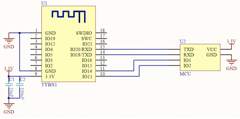
The I/O 11 pin is the low-power control pin of the module. Signals are sent by the MCU and received by the module.
The I/O 14 pin can wake up the MCU. Signals are sent by the module and received by the MCU. Interrupt pins are supported.
For more information about the I/O pins and RF features with which the Bluetooth module TYBN1 provides smart door locks, see TYBN1 Module Datasheet.
Things to note
Schematic diagrams
The TYBN1 module provides the following pins for smart door locks: the 3.3V power supply and UART user serial port. When you design a smart door lock, you must consider the wiring of low-power control pins. We recommend that you break the I/O 11 and I/O 14 pins out to implement lower-power control and MCU wake-up.
Antenna design
The TYBN1 module provided by Tuya applies to door locks. However, the metal structure of door locks might have an impact on the RF performance of antennas. Therefore, in the early layout design, the position and overall structure of an antenna must be optimized to minimize the impact on the RF performance.
The PCB antenna used by TYBN1 is a PCB antenna that supports a frequency band from 2.400 GHz to 2.483 GHz. For more information, see TYBN1 Module Datasheet.
Note:
- Make sure that the metal components such as the substrate medium and lock are not located directly below or above the printed antenna.
- Make sure that the printed antenna is away from the copper sheet. This maximizes the radiation performance of the antenna.
Is this page helpful?
YesFeedbackIs this page helpful?
YesFeedback


