TYBT8 Module Datasheet
TYBT8 is a low-power embedded Bluetooth module developed by Hangzhou Tuya Information Technology Co., Ltd. It consists of a highly integrated Bluetooth chip (TLSR8269) and a small number of peripheral circuits, with a built-in Bluetooth network communication protocol stack and robust library functions.
After a period of service, this module will become deprecated due to product upgrades and iterations, user requirements, production inventory, or other reasons. To improve the compatibility of your smart devices and minimize the impact on your use, Tuya continues to provide webpage documentation of deprecated modules, but no longer maintains or updates the documentation. The content herein is for reference only.
If you have any questions, submit a ticket to contact Tuya or consult Tuya’s account manager to request support. If you need similar substitute products, see BT8C-E Module Datasheet.
Overview
TYBT8 also contains a 32-bit low-power MCU, Bluetooth 2.4G radio, 512 KB flash, 32 KB SRAM, and nine reusable I/O interfaces.
Features
- Built-in 32-bit low power-consuming MCU, which can also be used as an application processor
Basic frequency: 48 MHz supported - Working voltage: 1.9 V to 3.6 V
- Peripheral equipment: three PWMs
- Bluetooth RF
- Compatible with Bluetooth 4.2
- RF data rate: up to 2 Mbit/s
- TX power: +7 dBm
- RX sensitivity: –92 dBm @ Bluetooth 1 Mbit/s
- Built-in AES encryption for hardware
- External antenna
- Working temperature: -40℃ to 105℃
Major application fields
- Intelligent LED
- Intelligent home appliances
- Intelligent low power-consuming sensors
Module interfaces
Dimensions and pin layout
TYBT8 provides a total of six pins on the front and back sides for plug-in assembly.
TYBT8 size: 8.5±0.35 mm (W)×12.7±0.35 mm (L)
Figure 2.1 shows the overall pin layout of TYBT8.

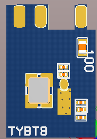
Figure 2.1 Overall pin layout of TYBT8
Pin definition
Table 2.1 describes the interface pins.
Table 2.1 TYBT8 interface pins
| No. | Symbol | I/O Type | Functions |
|---|---|---|---|
| 1 | ANT | I/O | RF signal input and output port |
| 2 | GND | P | Module power supply reference ground pin |
| 3 | PWM0 | I/O | Common I/O interface, which can be used for PWM output of LED drives |
| 4 | PWM1 | I/O | Common I/O interface, which can be used for PWM output of LED drives |
| 5 | PWM4 | I/O | Common I/O interface, which can be used for PWM output of LED drives |
| 6 | 3.3V | P | Module power supply input pin |
| TP1 | SWS | I/O | Test point: Bluetooth chip programming pin |
| TP2 | RST | I | Test point: Module reset pin |
| TP3 | TX | I/O | Serial port sending pin, which can be used as a common I/O interface |
| TP4 | RX | I/O | Serial port receiving pin, which can be used as a common I/O interface |
Note: P indicates power-supply pins, and I/O indicates input/output pins.
The SWS pin is used only for the programming of module firmware.
Electrical parameters
Absolute electrical parameters
Table 3.1 Absolute electrical parameters
| Parameter | Description | Minimum Value | Maximum Value | Unit |
|---|---|---|---|---|
| Ts | Storage temperature | -20 | 125 | ℃ |
| VCC | Power-supply voltage | -0.3 | 3.9 | V |
| Static electricity voltage (human model) | TAMB -25℃ | - | 2 | KV |
| Static electricity voltage (machine model) | TAMB -25℃ | - | 0.5 | KV |
Electrical conditions
Table 3.2 Normal electrical conditions
| Parameter | Description | Minimum Value | Typical Value | Maximum Value | Unit |
|---|---|---|---|---|---|
| Ta | Working temperature | -20 | - | 85 | ℃ |
| VCC | Working voltage | 1.9 | 3.3 | 3.6 | V |
| VIL | I/O low-level input | -0.3 | - | VCC x 0.3 | V |
| VIH | I/O high-level input | VCC x 0.7 | - | VCC | V |
| VOL | I/O low-level output | VSS | - | 0.3 | V |
| VOH | I/O high-level output | VCC - 0.3 | - | VCC | V |
Power consumption in operating mode
Table 3.3 TX power consumption during constant emission
| Symbol | Condition | Typical Value | Unit |
|---|---|---|---|
| ITX | Constant sending with 0 dBm output power | 15 | mA |
| IRX | Constant receiving | 12 | mA |
| IDC | Mesh connected | 27 | mA |
| Isleep | Sleep mode with I/O waked up | 10 | μA |
| Ideepsleep | Deep sleep mode | 1.7 | μA |
RF features
Basic RF features
Table 4.1 Basic RF features
| Parameter | Description |
|---|---|
| Frequency band | 2.4 GHz ISM band |
| Radio standard | Bluetooth 4.2 |
| Data transmission rate | 1 Mbit/s |
| Antenna type | External antenna |
RF output power
Table 4.2 TX power during constant emission
| Parameter | Minimum Value | Typical Value | Maximum Value | Unit |
|---|---|---|---|---|
| RF average output power | 3.8 | 7 | 8 | dBm |
| 20 dB modulation signal bandwidth (1 M) | - | 1300 | - | KHz |
RF RX sensitivity
Table 4.3 RX sensitivity
| Parameter | Rate | Minimum Value | Typical Value | Maximum Value | Unit |
|---|---|---|---|---|---|
| RX sensitivity | 1Mbit/s | -93 | -92 | -90 | dBm |
| Frequency offset error | 1Mbit/s | -300 | - | +300 | KHz |
| Co-channel interference suppression | - | - | -7 | - | dB |
Antenna information
Antenna types
TYBT8 uses an external spring antenna, and the specific gain and size can be customized according to customer requirements.
Antenna interference reduction
To ensure optimal RF performance, it is recommended that the antenna on the module be at least 15 mm away from other metal parts. If the antenna is wrapped with metal materials, the wireless signal will be significantly attenuated, thereby deteriorating the RF performance. Because the module is installed as a plug-in, reserve enough space for the antenna.
Packaging information and production instructions
Mechanical dimensions and size of the back pad
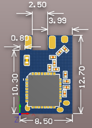
Figure 6.1 TYBT8 size diagram
Production instructions
-
For the in-line module developed by Tuya, wave soldering equipment is most preferred and manual soldering is less preferred. After being unpacked, the module must be soldered within 24 hours. Otherwise, it must be put into the drying cupboard where the RH is not greater than 10%, or it needs to be packaged under vacuum again and record the exposure time (the total exposure time cannot exceed 168 hours).
-
Soldering equipment and materials:
- Wave soldering equipment
- Wave soldering fixture
- Constant-temperature soldering iron
- Tin bar, tin wire, and flux
- Oven temperature tester
-
Baking equipment:
- Cabinet oven
- Anti-static heat-resistant pallets
- Anti-static heat-resistant gloves
-
The module needs to be baked in the following cases:
- The vacuum packing bag was found to be damaged before being unpacked.
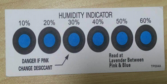
- There is no humidity indicator card (HIC) in the vacuum packing bag.
- After being unpacked, 10% and above circles on the HIC become pink.
- The total exposure time has been more than 168 hours since unpacking.
- More than 12 months have passed since the sealing date of the bag.
-
Baking settings:
- Temperature: 40°C and ≤ 5% RH for reel package and 125°C and ≤5% RH for tray package (please use the heat-resistant tray rather than plastic container)
- Time: 168 hours for reel package and 12 hours for tray package
- Alarm temperature: 50°C for reel package and 135°C for tray package
- Production-ready temperature after natural cooling: < 36°C
- Re-baking situation: If a module remains unused for over 168 hours after being baked, it needs to be baked again.
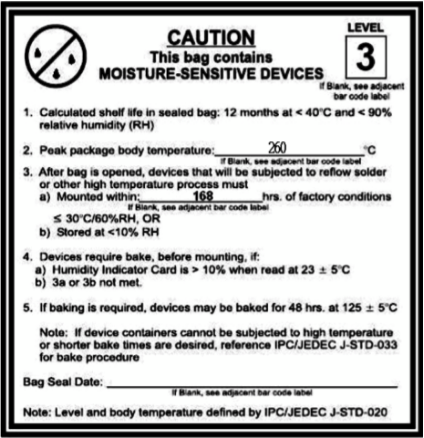
- If a batch of modules is not baked within 168 hours, do not use wave soldering to solder them. Because these modules are Level-3 moisture-sensitive devices, they are very likely to get damp when exposed beyond the allowable time. In this case, if they are soldered at high temperatures, it may result in device failure or poor soldering.
-
In the whole production process, take electrostatic discharge (ESD) protective measures.
-
To guarantee the quality of products, you must pay attention to the following items:
- The amount of soldering flux.
- The height of the wave peak.
- Whether the tin slag and copper content in the wave soldering tank exceed standards.
- Whether the window and thickness of the wave soldering fixture are appropriate.
- Whether the wave soldering oven temperature curve is reasonable.
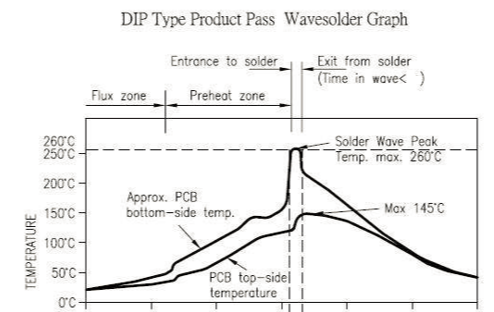
Recommended oven temperature curve and temperature
For oven temperature setting, refer to oven temperatures for wave soldering. The peak temperature is 260°C±5°C. The wave soldering temperature curve is shown below:
Recommended soldering temperature:
| Recommended wave soldering oven temperature | Recommended manual soldering temperature | ||
|---|---|---|---|
| Preheat temperature | 80 to 130 °C | Soldering temperature | 360±20°C |
| Preheat time | 75 to 100s | Soldering time | <3s/point |
| Peak contact time | 3 to 5s | NA | NA |
| Temperature of tin cylinder | 260±5°C | NA | NA |
| Ramp-up slope | ≤2°C/s | NA | NA |
| Ramp-down slope | ≤6°C/s | NA | NA |
Storage conditions
Storage conditions for a delivered module are as follows:
-
The moisture-proof bag is placed in an environment where the temperature is below 40°C and the relative humidity is lower than 90%.
-
The shelf life of a dry-packaged product is 12 months from the date when the product is packaged and sealed.
-
The package contains a humidity indicator card (HIC).
MOQ and packaging information
| Product number | MOQ (pcs) | Shipment packaging method | The number of modules per reel | The number of reels per carton |
|---|---|---|---|---|
| TYBT8 | 5600 | Tape reel | 1400 | 4 |
Is this page helpful?
YesFeedbackIs this page helpful?
YesFeedback


