Energy Metering Socket
This topic describes how to create an energy metering socket with the no-code solution on the Tuya Developer Platform.
This documentation is not generally available to the public. It applies to legacy SDKs, APIs, tools, or platforms. For the latest documentation, go to the Tuya Developer Platform Documentation Center.
Creating product
-
Log in to the Tuya Developer Platform.
-
Click Create.
-
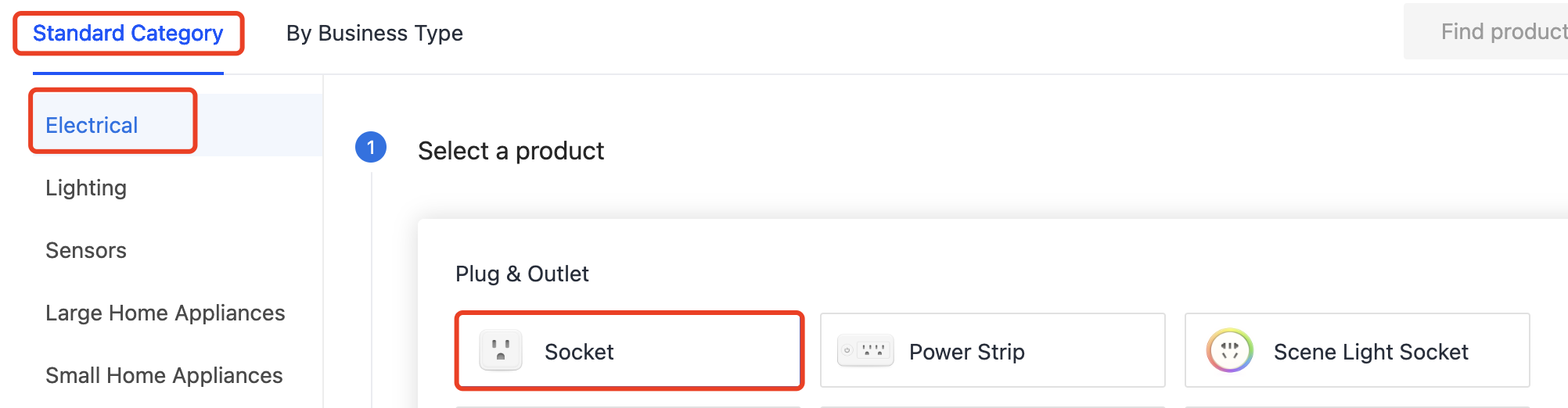
In the Standard Category tab, choose Electrical > Socket.
-
Choose TuyaOS. In the No-Code Development tab, select Wi-Fi and then Energy Statistics, and then click the product that appears.
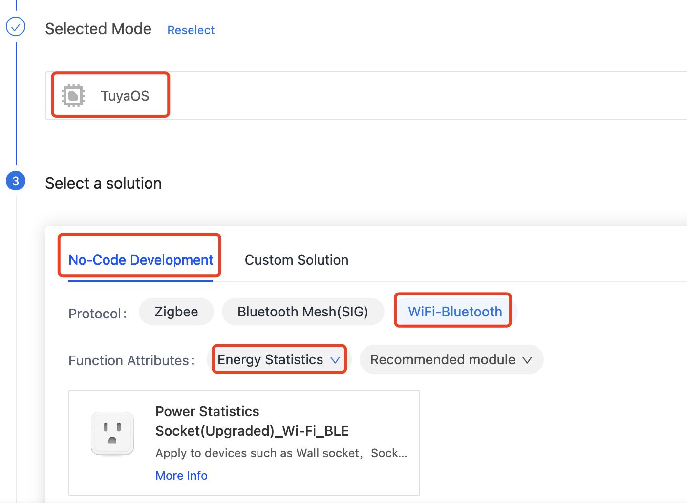
If the no-code solution does not meet your needs, you can try a custom solution.
-
Complete the required information.
-
(Required) Product Name: the name of the product, which will be displayed on the control panel in the mobile app.
-
(Optional) Product Model: the model of the product. Multiple models are separated by commas (,).
The product model is not displayed on the mobile app. You can enter the model number or customer’s product model to identify different products. You can modify product information in Product Overview later.
-
-
Click Create.
You will be directed to the Function Definition page.
Function definition
-
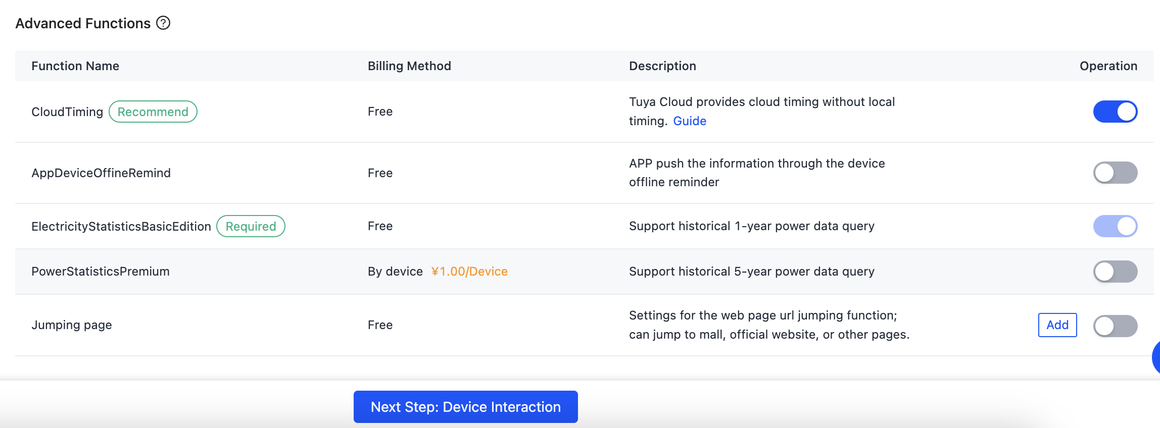
Select functions and click OK.
The required functions cannot be removed.
-
(Optional) Enable the advanced function as needed.
-
Proceed with Next Step: Device Interaction.
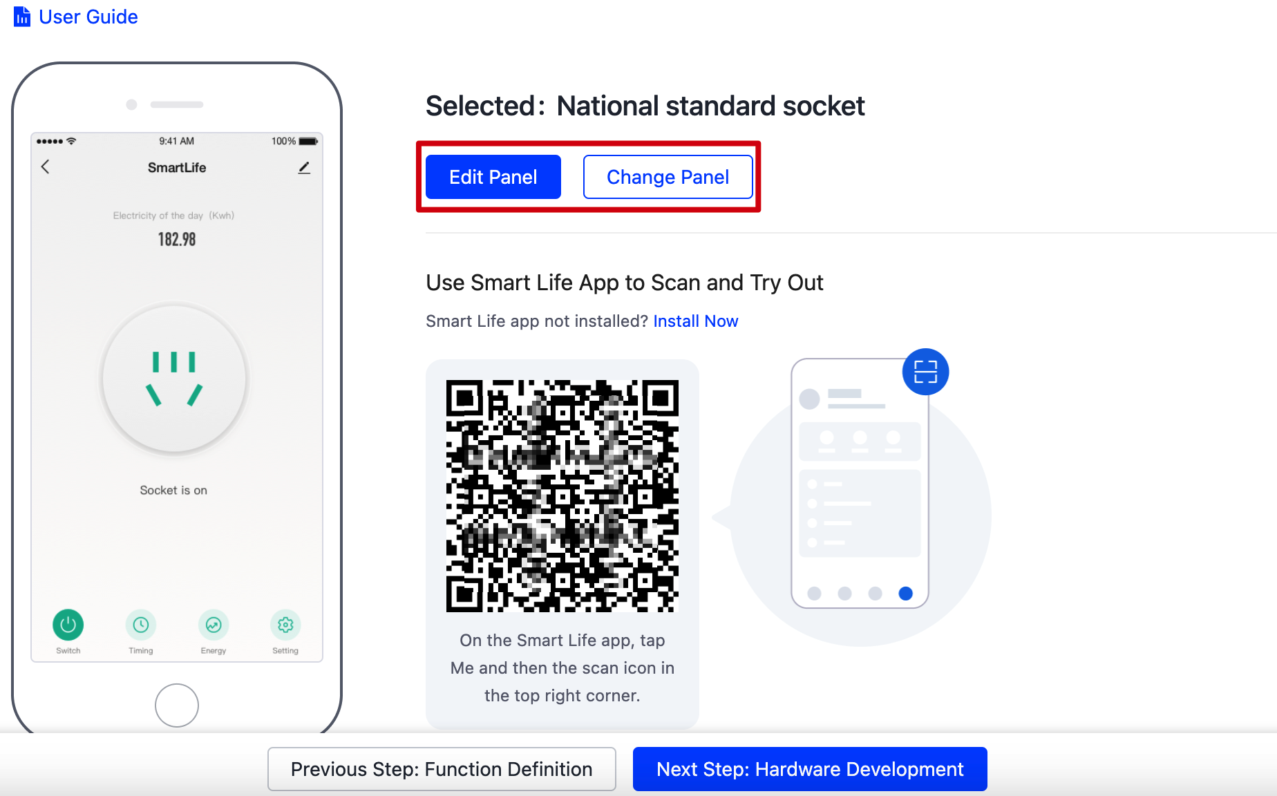
Selecting app panel
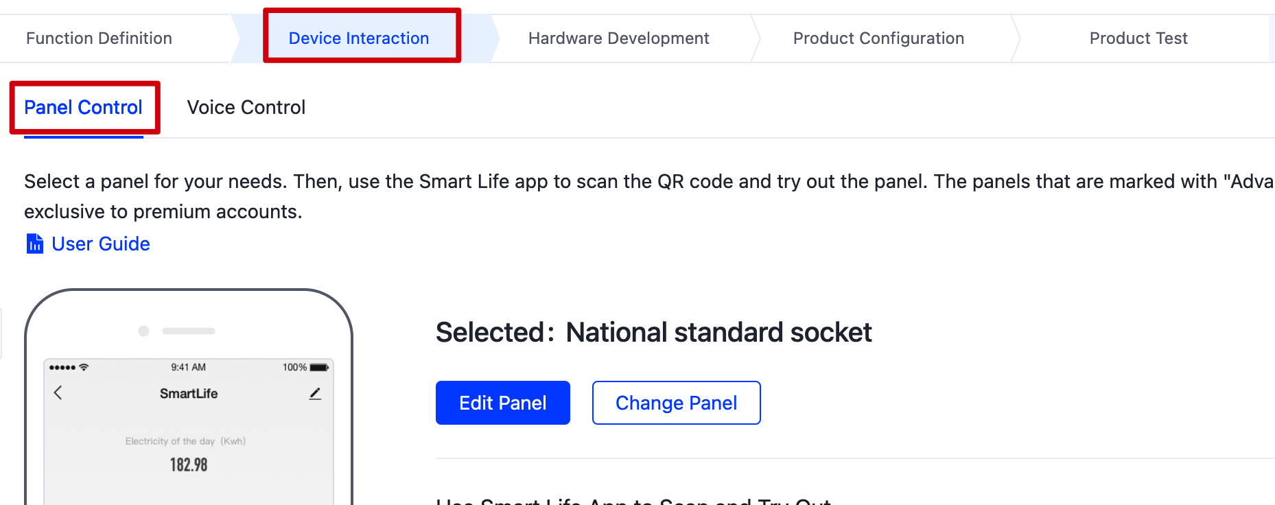
This section describes how to select and preview an app panel. You can follow the on-screen instructions to edit or customize a panel.
-
Hover over a panel and click Select to apply the panel.
Upgrading to an organization account can unlock more panels.
-
(Optional) Change and edit the selected panel. Scan the QR code to preview the panel on the mobile app.
-
Proceed with Next Step: Hardware Development.
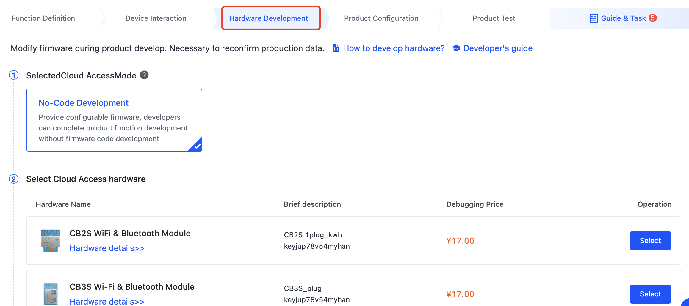
Hardware development
This section uses the WR3 Wi-Fi module as an example to describe the process. It is recommended a professional engineer perform this process.
-
Select a network module for your needs.
-
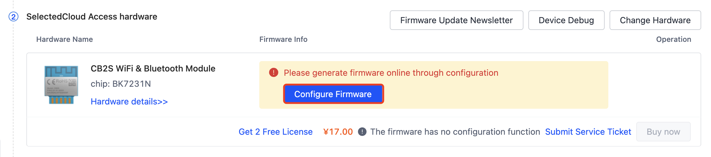
Configure the firmware parameters. The following table lists the parameters and their description.
Parameter type Parameter Description Energy metering Energy metering IC Select one as per your needs.
Only pulse counting chips are supported: BL0937 or HLW8012.Shunt resistor (mΩ) Valid values: 1 mΩ, 2 mΩ, 3 mΩ, 4 mΩ, and 5 mΩ Energy metering (CF) Connect to the CF pin of the energy metering chip. Voltage and current detection (CFI) Connect to the CF1 pin of the energy metering chip. Current and voltage switching (SEL) Connect to the SEL pin of the energy metering chip. - If the I/O pin of the module and the SEL pin of the energy metering chip are both high level, select Direct Connection.
- If there is an inverted triode or optocoupler between the I/O pin (high level) of the module and the SEL pin (low level) of the energy metering, select Inverted.
Calibration voltage (V) 120V or 220V. You can only calibrate the metering chip with the selected calibration voltage. - If the product can operate properly at both of these voltages, you can choose either of them as the calibration voltage.
- If the product cannot withstand 220V, set 120V as the calibration voltage.
Over-current protection (mA) Valid values: 0 to 30,000 mA Description:
- If over-current protection is needed, set a current limit in this field. It is recommended the limit be about 10% higher than the relay over-current protection limit.
- If over-current protection is not needed, set this field to 0.
Channel 1 Power button Select a pin from the drop-down list. Note that the specified pin cannot be configured for other features. Default power state Select one as per your needs. - Off: When the device is powered on, the relay is open.
- On: When the device is powered on, the relay is closed.
- Last state: When the device is powered on, the relay returns to the state before the last shutdown.
Relay Select a pin from the drop-down list. Note that the specified pin cannot be configured for other features. Indicator Select a pin from the drop-down list. Note that the specified pin cannot be configured for other features. Note: For a single-LED product, it is recommended to select Empty. For a dual-LED product, select a pin as per your needs.
Net connection setting Wi-Fi status indicator Select a pin from the drop-down list. Note that the specified pin cannot be configured for other features. Reset time/s The button hold time to reset the device.
Valid values: 3 to 10 seconds.LED status for Wi-Fi disconnection Set the LED behavior when the Wi-Fi socket is disconnected from the network. Description:
- For a single-LED product, it is recommended to set this field to Indicate Relay Status.
- For a dual-LED product, it is recommended to set this field to Light Off.
LED status for Wi-Fi connection Set the LED behavior when the Wi-Fi socket is connected to the network. Description:
- For a single-LED product, it is recommended to set this field to Indicate Relay Status.
- For a dual-LED product, it is recommended to set this field to Light On.
Trigger for the first-time pairing Set the trigger for pairing when the device is powered on for the first time. - Press and hold a button until the LED blinks: Press and hold a specific button until the network LED blinks to put the device in pairing mode.
- The LED blinks upon power on: The LED blinks upon the device is powered on for the first time, indicating the device enters pairing mode.
-
After all the parameters are set, click Generate Firmware.
-
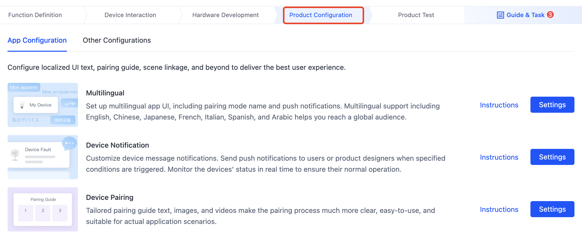
Proceed with Next Step: Product Configuration.
Product configuration
Configure the provided feature as needed. When you are done, proceed Next Step: Product Test.
Product test
Test the product with the Cloud Test app and submit the test report, or you can choose the Tuya Test service. Proceed with Release Product.
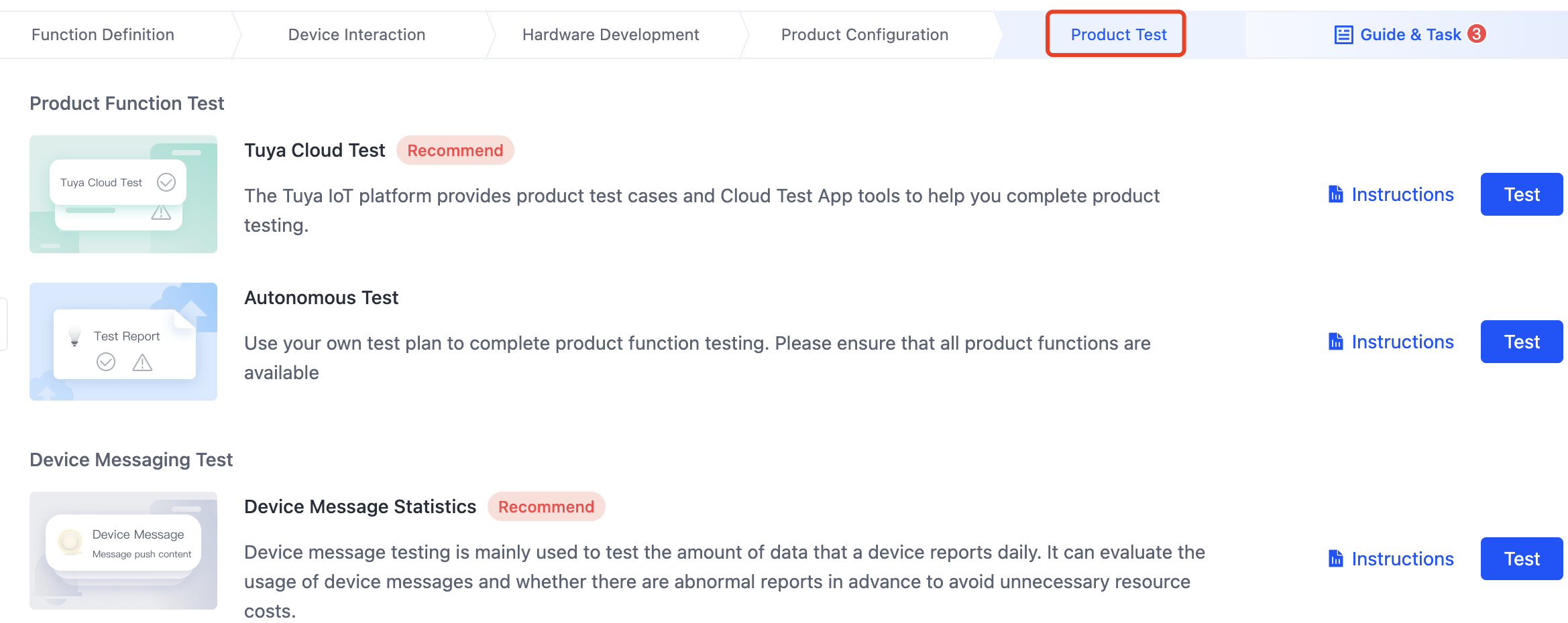
- The Tuya Cloud Test app is only available on Android.
- For more information, see Cloud Test App.
- Deleting a product that is in a developing or developed state will cause data loss and device anomalies. Proceed with caution.
Is this page helpful?
YesFeedbackIs this page helpful?
YesFeedback


